|
|

Table Of Contents
1.3.1 Reversible Mounting Bracket
1.4 Fan-Tray Assembly Installation
1.5 Power and Ground Installation
1.8 Card Installation and Turn-Up
1.8.3 Card Software Installation
1.9 Cable Description and Installation
1.9.2 Cable Installation Overview
1.9.3 Fiber Cable Installation
1.9.4 Coaxial Cable Installation
1.9.6 Alarm Cable Installation
1.10.4 Cisco Transport Controller
1.10.13 Environmental Specifications
Hardware Installation
This chapter provides procedures for installing the Cisco ONS 15327. Chapter topics include:
•
Installation Equipment
•
•
•
•
•
•
Note
Warning
Warning
Warning
Note
1.1 Installation Overview
When installed in an equipment rack, the ONS 15327 assembly is typically connected to a fuse and alarm panel that provides centralized alarm connection points and distributed power for the ONS 15327. Fuse and alarm panels are third-party equipment and are not described in this documentation. If you are unsure about the requirements or specifications for a fuse and alarm panel, consult the documentation for that product.
You can mount the ONS 15327 in a 19- or 23-inch rack. Including the fan tray, the shelf assembly weighs approximately 15 pounds without cards installed and 27 pounds fully loaded. An ONS 15327 is installed in a rack using reversible mounting brackets on each side of the shelf.
You can access the ONS 15327 cards, cables, connectors, power feeds, and fan tray through the front of the shelf assembly only. The CRIT, MAJ, MIN, and REM alarm LEDs visible on the XTC faceplate indicate whether a Critical, Major, Minor, or Remote alarm is present anywhere on the ONS 15327 assembly. These LEDs help you to quickly determine if any alarms are present on the assembly.
The ONS 15327 is powered using -48V DC power. Positive and negative power terminals are accessible on the front panel.
Warning
Table 1-1 lists the tasks required to install an ONS 15327.
Table 1-1 Installation Tasks
Mount the ONS 15327 in the rack.
See the "Rack Installation" section.
Install the fan-tray assembly.
Ground the equipment.
Install the MICs
Run the power cables and fuse the power connections.
Install the XTC cards
Install the optical and electrical cards
Install cables
1.2 Installation Equipment
You will need the following tools and equipment to install and test the ONS 15327.
1.2.1 Included Materials
These materials are shipped with the ONS 15327. The number in parentheses provides the quantity of the item included in the package.
•
•
•
•
1.2.2 User-Supplied Materials
These materials and tools are required but are not supplied with the ONS 15327.
•
•
•
The National Electrical Code recommends #12-14 AWG power cable.
•
•
•
•
•
•
•
•
1.2.2.1 Tools Needed
•
•
•
•
•
•
•
1.2.2.2 Test Equipment
•
•
•
Note
1.3 Rack Installation
The ONS 15327 is easily mounted in a 19- or 23-inch equipment rack. The shelf assembly projects 2 inches from the front of the rack. It mounts in both EIA-standard and Telcordia-standard racks. The shelf assembly is a total of 17 inches wide with no mounting ears attached. With the mounting ears attached, the shelf assembly is 19 inches wide.
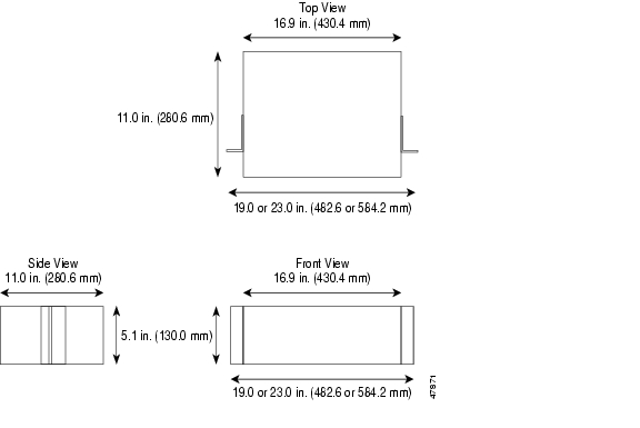
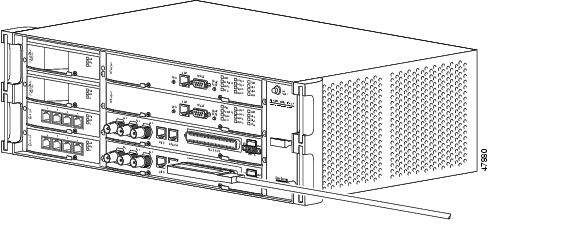
The ONS 15327 measures 5.1 inches high, 19 or 23 inches wide (depending on which way the mounting ears are attached), and 11 inches deep (13 x 48.3 x 28 cm). Figure 1-1 shows the dimensions of the ONS 15327 shelf assembly.
Figure 1-1 The ONS 15327 shelf assembly dimensions
1.3.1 Reversible Mounting Bracket
Caution
Caution
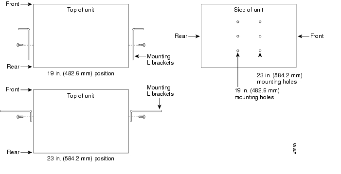
The shelf assembly comes with mounting brackets that can be reversed for use with a 19- or 23-inch rack. The following steps describe how to reverse the shelf assembly mounting bracket to fit a 19- inch rack.
Procedure: Reverse the Mounting Bracket to Fit a 19-Inch Rack
Step 1
Step 2
Step 3
The narrower side of the mounting bracket should be towards the front of the shelf assembly. Text imprinted on the mounting bracket should be visible and upside down.
Step 4
Step 5
Step 6
Figure 1-2 Reversing the mounting brackets (23-inch position to 19-inch position)
1.3.2 Mounting a Single Node
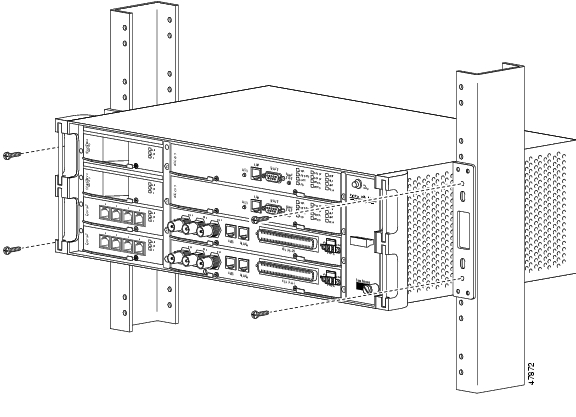
Mounting the ONS 15327 in a rack requires a minimum of 5.2 inches of vertical rack space (plus 1 inch for air flow). To ensure the mounting is secure, use two to four #12-24 mounting screws for each side of the shelf assembly. Figure 1-3 shows the rack mounting position for the ONS 15327.
Figure 1-3 Mounting an ONS 15327 in a rack
One person can install the shelf assembly using the mounting screws provided. For easier lifting, the shelf should be empty of cards and the fan tray.
Procedure: Mount the ONS 15327 in a Rack
Step 1
Step 2
Step 3
Step 4
You should use at least one set of the horizontal screw slots on the mounting brackets to prevent future slippage.
Step 5
1.3.3 Mounting Multiple Nodes
Most standard seven-foot racks can hold 12 ONS 15327s and a fuse and alarm panel.
Procedure: Mount Multiple ONS 15327s in a Rack
Step 1
Step 2
Step 3
1.4 Fan-Tray Assembly Installation
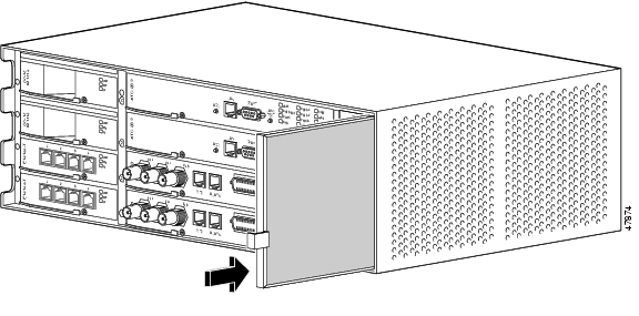
Facing the front of the ONS 15327, the fan-tray assembly is located on the right-hand side. The fan tray is a removable drawer that holds fans and fan-control circuitry for the ONS 15327. After you install the fan tray, you should not need to remove it unless a fan failure occurs or you need to replace, inspect or clean the fan-tray air filter.
The fan-tray assembly has an air filter on the right side of the fan tray that you can install and remove by hand. Remove and visually inspect this filter every 30 days. For inspection procedures, refer to the "Air Filter Inspection and Replacement" section on page 12-2. Spare filters should be kept in stock. If you are replacing the air filter, you must first move aside the cables that cross in front of it. You must install the air filter with its metal bracing against the fan tray.
Figure 1-4 Removing or replacing the fan-tray air filter
Caution
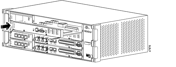
Procedure: Install the Fan-Tray Assembly
Step 1
Step 2
Step 3
Step 4
The FAN STATUS LED only illuminates when an XTC card is installed.
Figure 1-5 shows the location of the fan tray.
Figure 1-5 Installing the fan-tray assembly
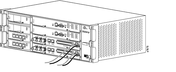
Procedure: Remove the Fan-Tray Assembly
Step 1
Step 2
Step 3
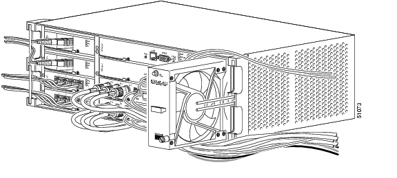
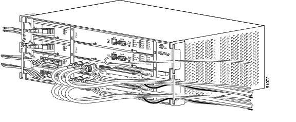
Figure 1-6 Removing a fan-tray assembly with installed cables
If the fan fails on the fan-tray assembly, replace the entire assembly. You cannot replace an individual fan. The FAN STATUS LED turns red when one or more fans fail. For a procedure that replaces the fan tray, see the "Install the Fan-Tray Assembly" section.
1.5 Power and Ground Installation
This section describes how to connect the ONS 15327 shelf assembly to the power supply. Terminate the chassis ground to either the office ground or rack ground before you install the power. Use the grounding lug to attach the ground cable to the shelf assembly according to local site practice.
Warning
Warning
You only ground one cable to ground the shelf assembly. Terminate the other end of the rack ground cable to ground according to local site practice.
If the system loses power or both XTC cards are reset, you must reset the ONS 15327 clock unless the node has been previously provisioned to use Simple Network Time Protocol (SNTP) to update the clock over the LAN.
Warning
Warning
Caution
Warning
Use the following wiring conventions:
•
•
Note
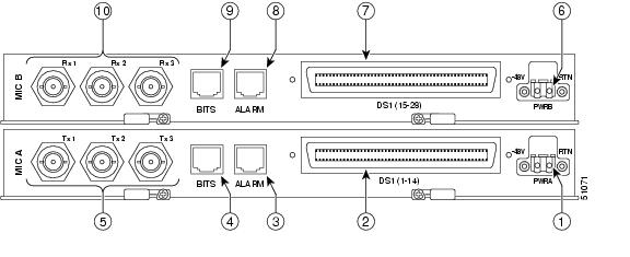
The ONS 15327 has redundant -48V DC power terminals on the MICs. The terminals are labeled PWR A and PWR B and are located on the far right-hand side of the MICs if you are facing the shelf assembly. Both MIC A and MIC B must be installed to create redundant power connections.
To install redundant power feeds, use four power cables and one ground cable. For a single power feed, only two power cables and one ground cable are required. Use #12 AWG cable and, to ensure circuit overcurrent protection, use a conductor with low impedance. However, the conductor must have the capability to safely conduct any fault current that might be imposed. Do not use aluminum conductors.
The MIC power connector is shipped with the fastening screws inserted but not tightened. The screws may have tightened due to vibration during shipping. Make sure the screws are loose before attempting to remove the connector.
Warning
Warning
Procedure: Install Redundant Power Feeds
Step 1
The ground connection point is located on the left-hand side panel as you face the ONS 15327.
Note
Step 2
Step 3
Warning
Step 4
Step 5
See the "Card Installation and Turn-Up" section for installation in instructions.
Warning
Caution
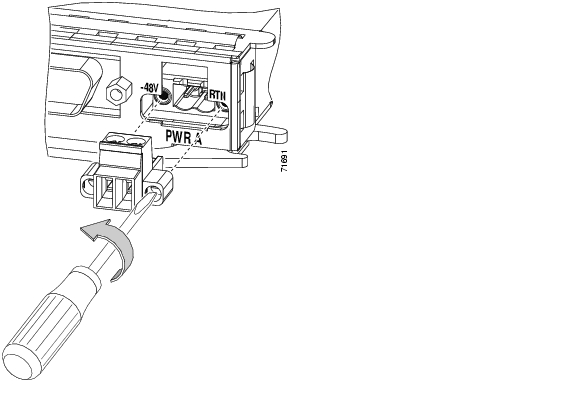
Step 6
Figure 1-7 Removing the MIC power connector
Step 7
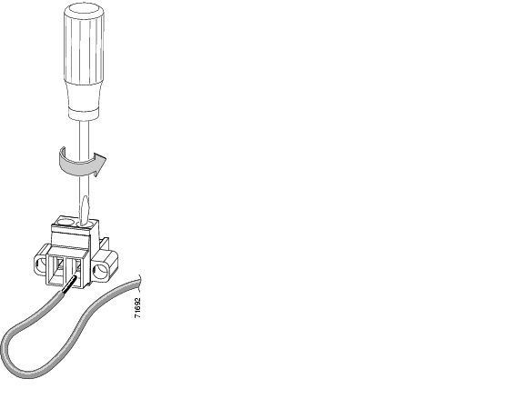
Step 8
Figure 1-8 Inserting a power cable into the MIC power connector
Step 9
Step 10
Step 11
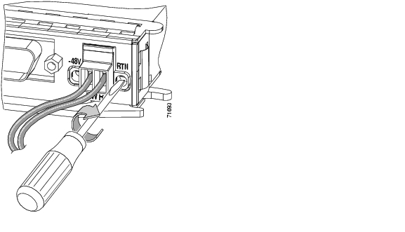
Step 12
Figure 1-9 Installing the MIC power connector
.
Step 13
Step 14
Figure 1-10 shows redundant power connected to an ONS 15327.
Figure 1-10 Redundant power connected to an ONS 15327
1.5.1 Ferrite Installation
Place third-party ferrites on power cables to dampen electromagnetic interference (EMI) from the ONS 15327. Ferrites must be added to meet the requirements of GR 1089. Refer to the ferrite manufacturer documentation for proper use and installation of the ferrites.
Procedure: Attach Ferrites to Power Cabling
Use a single block ferrite Fair Rite 0443164151 for each pair of cables.
Step 1
Step 2
1.6 Alarm Cutoff
Visual and audible alarms are typically wired to trigger an alarm light at a central alarm collection point when the corresponding contacts are closed. The alarm cutoff (ACO) function stops (turns off) the alarm signal being transmitted to the alarm collection point.
To activate the ACO function, press the ACO button on the XTC card faceplate. The ACO button clears all audible alarm indications. After clearing the audible alarm indication, the alarm is still present on the Alarms tab in Cisco Transport Controller (CTC) and appropriate action is needed to clear the alarm. For information about connecting to alarm collection equipment, See the "Alarm Cable Installation" section. For procedures that resolve alarms, refer to Chapter 14, "Alarm Troubleshooting."
1.7 Timing Installation
The ONS 15327 supports two Building Integrated Timing Supply (BITS) clock interfaces. The physical connection is provided through an RJ-45 connector on each MIC. Two pins on each RJ-45 are used for BITS timing. BITS 1 In (MIC A) and BITS 2 In (MIC B) use pins 3 and 4. BITS 1 Out (MIC A) and BITS 2 Out (MIC B) use pins 7 and 8. The BITS 1 pins support output and input from the first external timing device. The BITS 2 pins perform the identical functions for the second external timing device. Table 1-2 lists the pin assignments for the BITS timing pin fields. For more information about connecting BITS timing to the ONS 15327, See the "BITS Cable Installation" section.
Note
1.8 Card Installation and Turn-Up
Caution
ONS 15327 cards have electrical plugs at the back that plug into electrical connectors on the shelf assembly backplane. When the ejectors are fully closed, the card plugs into the assembly backplane. Figure 1-11 shows XTC card installation (which is the same as MIC installation) and Figure 1-12 shows high-speed card installation.
Warning
Warning
Note
1.8.1 Slot Requirements
The ONS 15327 shelf assembly has eight card slots; four high speed slots, two Cross-Connect, Timing and Control (XTC) slots, and two Mechanical Interface Card (MIC) slots. The wider slots host the XTC cards and MICs. The narrower, high-speed slots host Ethernet, OC-3, OC-12, and OC-48 cards.
The XTC slots host both XTC-14 and XTC-28-3 cards. XTC cards are required for system operation. The MIC slots host MIC A and MIC B cards. The MIC slots are keyed to ensure that you install the MICs in the correct slot. Install MIC A in the bottom MIC slot (Slot 8) and MIC B in the top MIC slot (Slot 7). MICs are also required for system operation. Make DS-1 and DS-3 connections using the connectors on the MICs. Refer to Chapter 13, "Card Reference," for more information about ONS 15327 cards.
Table 1-3 lists the number of ports, line rates, connector options, and connector locations for ONS 15327 optical and electrical cards.
Procedure: Install ONS 15327 Cards
Step 1
Step 2
Step 3
Step 4
Figure 1-11 Installing an XTC card (XTC 28-3)
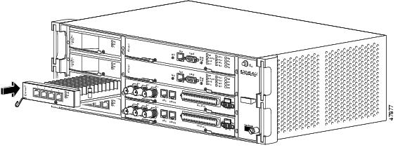
Figure 1-12 Installing a high-speed card (E10/100-T)
1.8.2 Card Turn-Up
The procedure for turning up ONS 15327 cards is slightly different for each card. Before installing any XTC or high-speed cards, install at least one MIC and apply power to the shelf assembly. First install MIC A in Slot 8. After successfully connecting the power to MIC A, install MIC B followed by the XTC cards. Install any high-speed cards after you have successfully installed and turned up the XTC cards and MICs. Follow the steps in this section to verify card turn-up.
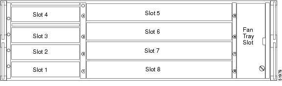
The card turn-up procedures reference the slot numbers for the ONS 15327. Figure 1-13 shows the location and corresponding number of each slot.
Figure 1-13 ONS 15327 slot numbering
Note
Warning
Procedure: Verify Successful Turn-Up of MICs
Step 1
The slots are keyed to ensure that cards are installed in the correct slot.
Step 2
Step 3
The fans will only activate if at least one XTC card is installed.
Step 4
Step 5
Warning
Step 6
Step 7
Step 8
Step 9
Refer to Chapter 2, "Software Installation," for more information about using CTC.
Procedure: Verify Successful Turn-Up of XTC Cards
Step 1
Slot 6 is the working XTC slot.
Step 2
Step 3
Step 4
Step 5
Slot 5 is the protect XTC slot.
Step 6
Step 7
Step 8
Step 9
Refer to Chapter 2, "Software Installation" for more information about using CTC.
Procedure: Verify Successful Turn-Up of High-Speed Cards
Step 1
Step 2
Step 3
Step 4
Step 5
Step 6
Warning
1.8.3 Card Software Installation
After you install an ONS 15327 card in a valid card slot, the card's software automatically updates to the version that operates correctly with the software installed on the XTC. To verify the current version of software installed on the XTC, click Help and then click About CTC. Refer to Chapter 2, "Software Installation" for more information about using CTC.
Note
1.9 Cable Description and Installation
This section explains how to install fiber-optic, DS-3 (coaxial), DS-1 (CHAMP), and twisted-pair cables.
1.9.1 Cabling Types
ONS 15327 cables use cable guides at each side of the front of the shelf assembly to economize shelf space and facilitate cable management. The following types of cables are used with the ONS 15327:
•
•
•
•
1.9.2 Cable Installation Overview
Because the ONS 15327 supports a large number of interfaces on the front panel, proper cable management and the correct cabling sequence during installation are required.
1.9.2.1 Cable Guides
The ONS 15327 has cable guides located on each side of the front of the shelf assembly. The cable guides ensure that the proper bend radius is maintained in the fibers and that all other cables are properly routed. To remove cable guides, take out the screws that anchor them to the side of the shelf assembly.
Figure 1-14 Managing front panel cables with locking cable guides
1.9.2.2 Cabling Sequence and Location
The two cable management considerations are the sequence of cable installation and the location of cable routing. To maintain access to all of the connectors during cable installation, cables must be attached to the MICs in the following order starting with MIC A (the bottom MIC) and repeating for MIC B:
1.
2.
3.
4.
5.
After attaching all of the cables to the MICs, route the cables out through the bottom right cable guide and snap it closed. Tie wrap the cables according to local site practice. Leave enough slack to remove the fan-tray assembly and fan filter.
You do not need to connect cables for the XTCs and high-speed cards in any particular order. Route XTC cables through the top right cable guide. Route high-speed cables out through the corresponding cable guides on the left-hand side of the shelf assembly. Figure 1-15 shows the order in which you should install cables on the ONS 15327.
Figure 1-15 The cable installation sequence
1.9.3 Fiber Cable Installation
Caution
ONS 15327 OC-12 and OC-48 cards have SC connectors and the OC-3 cards have LC connectors. To install fiber-optic cables in the ONS 15327, a fiber cable with the corresponding connector type must be connected to the transmit and receive ports on the ONS 15327 cards. On ONS 15327 OC-12 and OC-48 card ports, the left-hand connector is the transmit port and the right-hand connector is the receive port. Cisco recommends that you label the transmit and receive ports and the working and protection fibers at each end of the fiber span to avoid confusion with cables that are similar in appearance.
Warning
Procedure: Install and Route Fiber-Optic Cables in the ONS 15327
Step 1
Note
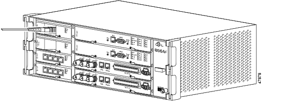
Figure 1-16 Installing a fiber-optic cable
Step 2
Step 3
Step 4
See the "Cable Guides" section for more information about cable management.
1.9.4 Coaxial Cable Installation
DS-3s connect to the ONS 15327 using coaxial cables and connectors. Cisco recommends connecting an RG-59/U cable to a patch panel; RG-59/U cable is designed for long runs of up to 450 feet. Use a compatible straight male BNC connector to connect the cable to the DS-3 ports on the MICs. The transmit (TX) ports on MIC A and the receive (RX) ports on MIC B use the same type of connector.
Caution
Procedure: Install Coaxial Cable With BNC Connectors
Step 1
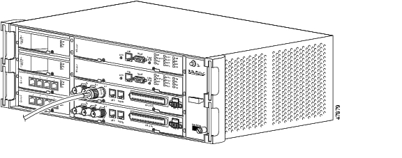
Figure 1-17 shows how to connect a coaxial cable to the ONS 15327 MIC.
Figure 1-17 Installing a coaxial cable with BNC connectors
Step 2
Step 3
Step 4
Step 5
Label all cables at each end of the connection to avoid confusion with cables that are similar in appearance.
1.9.5 DS-1 Cable Installation
DS-1s support CHAMP connector cabling. This section provides information about the DS-1 cables and connectors.
Installing CHAMP connector DS-1 cables requires 64-pin bundled cable connectors with a 64-pin female CHAMP connector. You need CHAMP connector #552276-1 for the receptacle side and #1-552496-1 for the right-angle shell housing, or their functional equivalents. The corresponding 64-pin male CHAMP connector on the MIC supports one receive (in) and one transmit (out) for each DS-1 port for the corresponding XTC.
Because each DS1-14 connection supports 14 DS-1 ports, only 56 pins (28 pairs) of the 64-pin connector are used. Prepare one 56-wire cable for each DS-1 connection. Table 1-4 shows the pin assignments for the CHAMP connectors on the ONS 15327 MICs.
Caution
Procedure: Install DS-1 CHAMP Cables on a MIC
Step 1
Step 2
Figure 1-18 shows DS-1 cable installation.
Step 3
Figure 1-18 Installing a DS-1 cable
1.9.6 Alarm Cable Installation
The alarm cables attach to the MICs using twisted-pair cables terminated with an RJ-45 connector on the end that plugs into the ALARM port. The other end of the cable plugs into the alarm-collection equipment. Terminate this end of the cable according to local site practice.
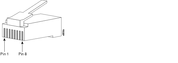
The pins on the ALARM port correspond to the six external alarm inputs and the two external alarm outputs (controls) that can you can define using CTC (for procedures, refer to the "Using Virtual Wires" section on page 7-17). Alarms 2, 4, and 6 correspond to MIC A and alarms 1, 3, and 5 correspond to MIC B. Alarm output 1 corresponds to MIC B and alarm output 2 corresponds to MIC A. Table 1-5 shows the input alarm pinouts and the corresponding alarm numbers assigned to each MIC/port. Table 1-6 shows the output alarm pinouts. Refer to these tables when connecting alarm cables to the ONS 15327. See Figure 1-19 for RJ-45 pin numbering.
Table 1-5 Alarm Input Pin Assignments
2
15
Alarm 2+
6
Alarm 2-
4
33
Alarm 1+
4
Alarm 1-
6
51
Alarm 0+
2
Alarm 0-
Table 1-6 Alarm (External Control) Output Pin Assignments
2
17
Contact+
8
Contact-
Figure 1-19 Pins 1 and 8 on the RJ-45 connector
1.9.7 BITS Cable Installation
The BITS cables attach to the MICs using twisted-pair cables terminated with an RJ-45 connector on the end that plugs into the BITS port. The other end of the cable plugs into the BITS clock. Terminate this end of the cable according to local site practice.
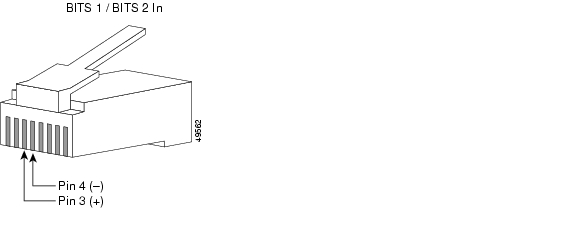
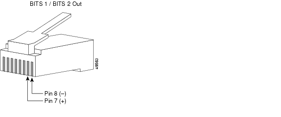
Each MIC has one BITS input and one BITS output. The BITS inputs and outputs have corresponding pins on the RJ-45 BITS ports. The BITS 1 inputs and outputs are on MIC A and the BITS 2 inputs and outputs are on MIC B. See Table 1-7, Figure 1-20, and Figure 1-21 when connecting BITS cables to the ONS 15327.
Table 1-7 BITS Cable Pin Assignments
BITS 1 In
BITS 2 In3
BITS Input+
4
BITS Input-
BITS 1 Out
BITS 2 Out7
BITS Output+
8
BITS Output-
Figure 1-20 BITS In pins on the RJ-45 connector
Figure 1-21 BITS Out pins on the RJ-45 connector
1.10 Hardware Specifications
1.10.1 Slot Assignments
•
•
•
•
1.10.2 Cards
•
•
•
•
•
•
•
•
•
•
1.10.3 Configurations
•
•
•
•
•
•
1.10.4 Cisco Transport Controller
•
•
1.10.5 External LAN Interface
•
1.10.6 TL1 Craft Interface
•
•
1.10.7 Modem Interface
•
•
1.10.8 Alarm Interface
•
•
•
1.10.9 Database Storage
•
1.10.10 BITS Interface
•
•
1.10.11 System Timing
•
•
•
•
1.10.12 Power Specifications
•
•
•
•
1.10.13 Environmental Specifications
•
•
1.10.14 Dimensions
•
•
•
•
![]()
![]()
![]()
![]()
![]()
![]()
![]()
![]()
Posted: Mon Feb 25 05:45:57 PST 2008
All contents are Copyright © 1992--2008 Cisco Systems, Inc. All rights reserved.
Important Notices and Privacy Statement.