|
|

Table Of Contents
12.1 Air Filter Inspection and Replacement
12.2 Fan-Tray Assembly Replacement
12.4 Database Backup and Restore
12.5 Reverting to an Earlier Software Load
12.6 XTC-14 Card to XTC-28 Card Upgrade
12.8 Inhibit Protection Switching
12.10.1 Perform a Facility Loopback on a Source XTC Card
12.10.2 Perform a Hairpin Circuit on a Source Node XTC Card
12.10.3 Perform a Hairpin on a Destination Node XTC Card
12.10.4 Perform a Terminal Loopback on a Destination XTC Card
12.10.5 Perform a Facility Loopback on a Destination XTC Card
12.11 Creating Diagnostic Files
12.13 Power Down the ONS 15327
Maintenance
This chapter describes procedures that can be necessary to maintain the Cisco ONS 15327, including:
•
Air filter inspection and replacement
•
•
•
•
•
•
•
•
•
•
•
12.1 Air Filter Inspection and Replacement
The Cisco ONS 15327 contains an air filter that should be removed and visually inspected approximately every 30 days, depending on the cleanliness of the operating environment. The filter is reusable and made of a gray open-cell polyurethane foam, specially coated to provide fire and fungi resistance. Figure 12-1 illustrates the reusable fan-tray air filter. You do not need to remove the fan-tray assembly to remove the air filter.
Procedure: Inspect and Clean the Reusable Air Filter
Step 1
Step 2
Step 3
Step 4
Note
Step 5
Warning
Step 6
Figure 12-1 Removing and replacing the reusable fan-tray air filter
12.2 Fan-Tray Assembly Replacement
The fan tray is a removable drawer that holds fans and fan-control circuitry for the ONS 15327. You should not need to remove the fan-tray assembly unless a fan failure occurs and you must replace the fan-tray assembly. You cannot replace individual fans.
Procedure: Replace the Fan-Tray Assembly
Step 1
Step 2
Step 3
Step 4
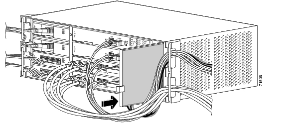
Figure 12-2 Removing a fan-tray assembly with installed cables
Step 5
Caution
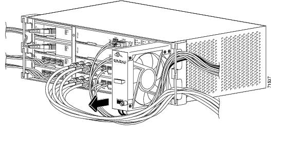
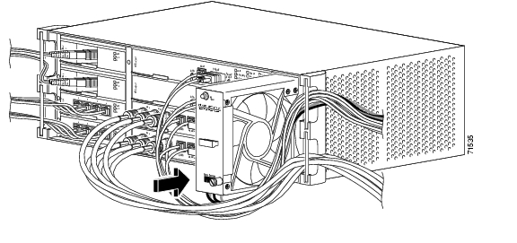
Figure 12-3 Replacing the fan-tray assembly
Step 6
Step 7
Note
12.3 System Reset
You can reset the ONS 15327 XTC card using the Cisco Transport Controller (CTC) software, or by physically reseating the XTC card (card pull). A software reset reboots the XTC and reloads the operating system and the application software. Additionally, a card pull reset temporarily removes power from the XTC and clears all buffer memory.
You can apply a software reset to either an active or standby XTC without affecting traffic, but you should only perform a card pull on a standby XTC. If you need to perform a card pull on an active XTC, put the XTC into standby mode first by performing a software reset on the card.
Warning
Note
Procedure: Perform a Software Reset
Step 1
Step 2
Step 3
Step 4
Step 5
Step 6
Note
Procedure: Perform a Card Pull
Note
Caution
Step 1
Step 2
Step 3
Step 4
Step 5
12.4 Database Backup and Restore
Each XTC card installed in the ONS 15327 contains two copies of the database. A save to the flash memory is written to the standby database, and the standby database then becomes the active database. The previously active database then becomes available for writing the next time. With dual XTCS, the standby XTC keeps both copies of the database synchronized with the active XTC as changes are made so that it is ready to take over control as needed. You can also store a back-up version of the database on the workstation running CTC. Backing up the database should be part of a regular ONS 15327 maintenance program at approximately weekly intervals and should also be completed when preparing an ONS 15327 for a pending natural disaster, such as a flood or fire.
Caution
Caution
Note
Note
Procedure: Backup the Database
Step 1
Step 2
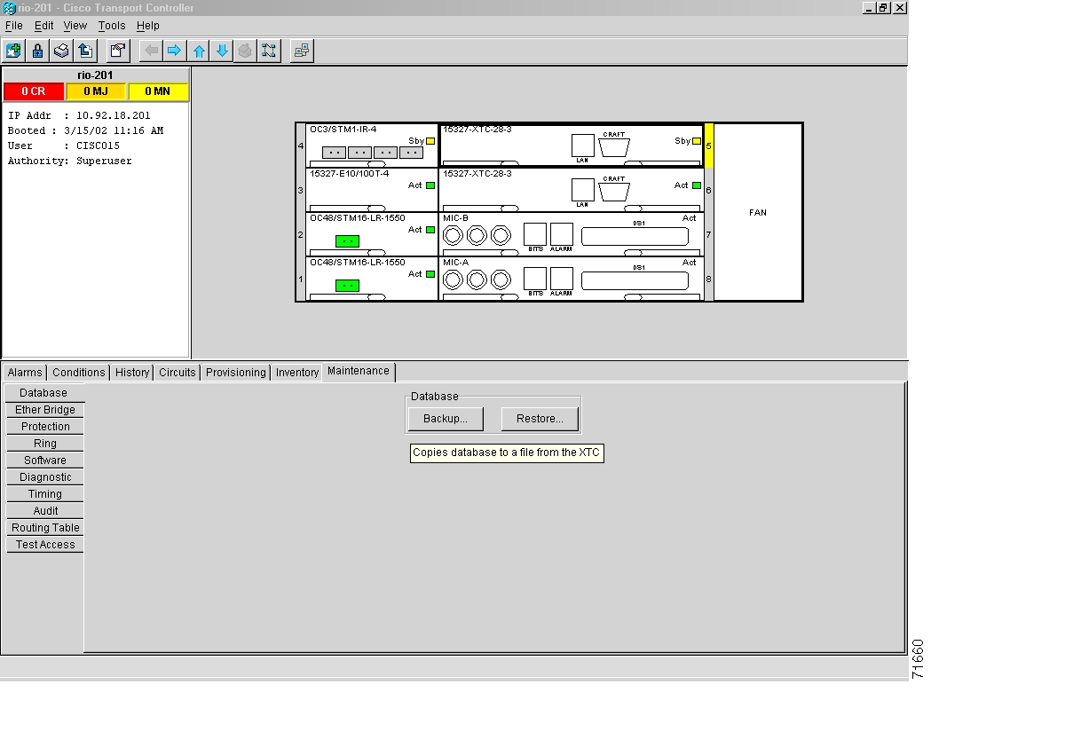
Figure 12-4 Backing up the ONS 15327 database
Step 3
Step 4
Step 5
Procedure: Restore the Database
Caution
Note
Step 1
Step 2
Step 3
Step 4
Step 5
Step 6
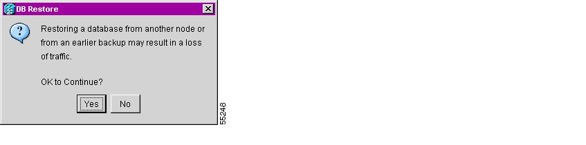
Figure 12-5 Restoring the database-traffic loss warning
Step 7
Figure 12-6 Restoring the XTC database-in-progress notification
Step 8
Step 9
12.5 Reverting to an Earlier Software Load
True Revert allows the system to revert to the protect system software image and its attendant database. The reversion does not affect DCC connectivity or traffic on circuits provisioned prior to the activation of the working software load. All versions of ONS 15327 software support this feature.
The ONS 15327 supports a working and protect software version on each XTC. The protect software version saves the provisioning that existed when the working load was activated. This means that the protect software load can only reinstate the circuits provisioned before the working load was activated. Circuits provisioned after the activation of the working load are lost during a revert.
When you click the Activate button after a software upgrade, the XTC copies the current working database and saves it in a reserved location in the XTC flash memory. If you later need to revert to the original working software load from the protect software load, the saved database installs automatically. You do not need to restore the database manually or recreate circuits.
Warning
Tip
Note
Note
Procedure: Revert to an Earlier Software Load
Step 1
Step 2
Step 3
Step 4
Step 5
Step 6
Step 7
Step 8
Step 9
The Revert button activates the protect software load. The ONS15327 node reboots and loses its connection to the CTC.
Step 10
Step 11
Step 12
The browser downloads the CTC applet for the standby software load.
12.6 XTC-14 Card to XTC-28 Card Upgrade
This section explains how to upgrade XTC-14 cards to XTC-28 cards on an ONS 15327 with live traffic. The procedure is non-service affecting; the upgrade will cause a switch less than 50 ms in duration.
Note
Note
Step 1
a.
b.
c.
d.
e.
f.
Note
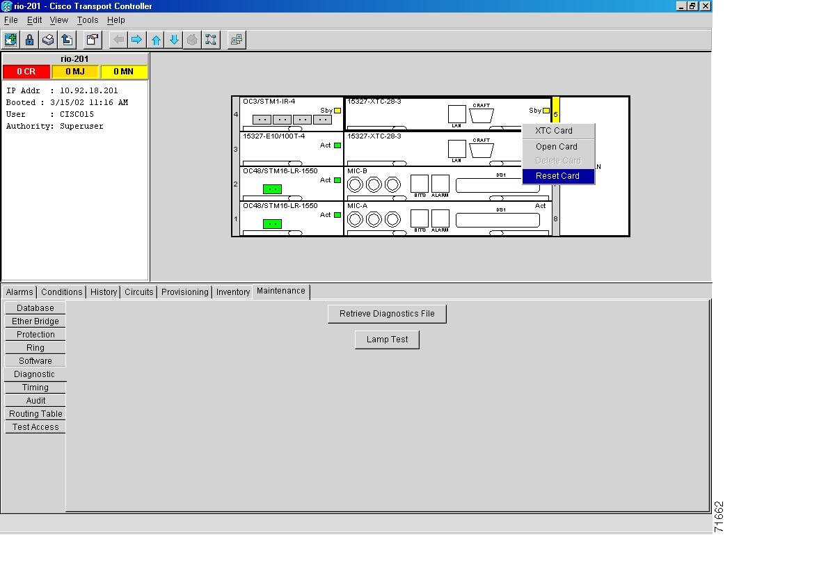
Step 2
a.
b.
Figure 12-7 Resetting the XTC card
Step 3
a.
b.
c.
d.
e.
Step 4
12.7 Span Upgrades
A span is the optical fiber connection between two ONS 15327 nodes. In a span upgrade, the transmission rate of a span is upgraded from a lower to a higher OC-N signal but all other span configuration attributes remain unchanged. With multiple nodes, a span upgrade is a coordinated series of upgrades on all nodes in the ring or protection group in which traffic carried at a lower OC-N rate is transferred to a higher OC-N. You can perform in-service span upgrades for the following ONS 15327 cards:
•
•
•
To perform a span upgrade, the higher-rate/long-reach optical card must replace the lower-rate/intermediate-reach card in the same slot. If the upgrade is conducted on spans residing in a BLSR, all spans in the ring must be upgraded. The protection configuration of the original lower-rate/intermediate-reach optical card (two-fiber BLSR, UPSR, and 1+1) is retained for the higher-rate/long-reach optical card.
When performing span upgrades on a large number of nodes, Cisco recommends that you upgrade all spans in a ring consecutively and in the same maintenance window. Until all spans are upgraded, mismatched card types will be present.
The Span Upgrade procedures require at least two technicians (one at each end of the span) who can communicate with each other during the upgrade. Upgrading a span is non-service affecting and will cause no more than three switches, each of which is less than 50 ms in duration. The Span Upgrade procedures can also be used to perform span downgrades.
Cisco recommends using the Span Upgrade Wizard to perform span upgrades from OC-12 to OC-48. Manual Span Upgrade procedures are mainly provided for OC-12 IR to OC-12 LR or OC-48 IR to OC-48 LR span upgrades, or as error recovery for the wizard. The Span Upgrade Wizard and the Manual Span Upgrade procedures require at least two technicians (one at each end of the span) who can communicate with each other during the upgrade. Upgrading a span is non-service affecting and will cause no more than three switches, each of which is less than 50 ms in duration.
Warning
Caution
Note
Note
BLSR Out of Sync alarms will be raised during span upgrades and will clear when the upgrade of all nodes is complete; a four-node BLSR can take up to five minutes to clear all of the Out of Sync alarms. Allow extra time for a large BLSR to clear all of the Out of Sync alarms.
Note
Choose from four span upgrade options:
•
•
•
•
Downgrading can be performed to back out of a span upgrade. The procedure for downgrading is the same as upgrading except that you choose a lower-rate/intermediate-reach card type. You cannot downgrade if circuits exist on the STSs that will be removed (the higher STSs).
Note
BLSR Out of Sync alarms will be raised during span upgrades and will clear when the upgrade of all nodes is complete. Allow extra time for a large BLSR to clear all of the Out of Sync alarms.Procedure: Perform a Span Upgrade Using the Span Upgrade Wizard
Warning
Caution
Note
Note
Step 1
a.
b.
c.
An unresolved alarm or abnormal condition is the most probable reason for upgrade failure. If alarms are present, refer to Chapter 14, "Alarm Troubleshooting."
Step 2
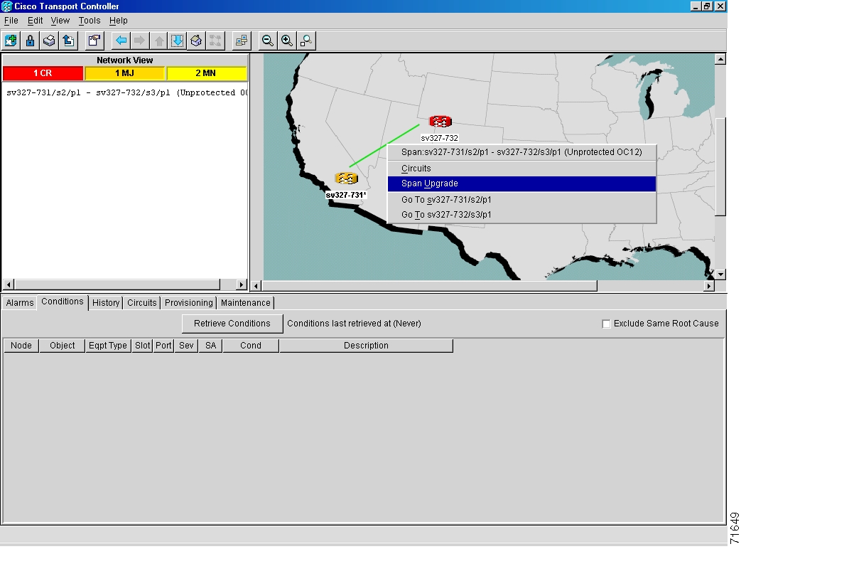
Step 3
Figure 12-8 Span pull-down menu
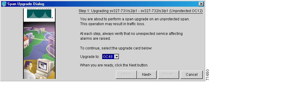
Step 4
Note
Figure 12-9 Beginning the Span Upgrade Wizard
Note
Procedure: Perform a Manual Span Upgrade on a Two-Fiber BLSR
All spans connecting the nodes in a BLSR must be upgraded before the added bandwidth is available.
Step 1
a.
b.
An unresolved alarm or abnormal condition is the most probable reason for upgrade failure.
Step 2
a.
b.
c.
d.
e.
f.
Step 3
Step 4
Step 5
Step 6
Step 7
Step 8
Step 9
a.
b.
c.
d.
e.
f.
The forced switch clears and traffic is running. If you have lost traffic, perform a downgrade. The procedure for downgrading is the same as upgrading except that you choose a lower-rate/intermediate-reach card.
Note
Step 10
When all spans in the BLSR have been upgraded, the span upgrade is complete.Procedure: Perform a Manual Span Upgrade on a UPSR
Step 1
a.
b.
An unresolved alarm or abnormal condition is the most probable reason for upgrade failure.
Step 2
a.
b.
c.
Step 3
Step 4
Step 5
Step 6
Step 7
Step 8
Step 9
a.
b.
c.
The forced switch clears and traffic is running. If you have lost traffic, perform a downgrade. The procedure for downgrading is the same as upgrading except that you choose a lower-rate/intermediate-reach card.
Note
Procedure: Perform a Manual Span Upgrade on a 1+1 Protection Group
When upgrading a 1+1 group, upgrade the protect line first regardless of which line is active. Both lines in a 1+1 group must be upgraded before the added bandwidth will be available.
Note
Step 1
a.
b.
An unresolved alarm or abnormal condition is the most probable reason for upgrade failure.
Step 2
a.
b.
c.
d.
e.
Step 3
Step 4
Step 5
Step 6
Step 7
Step 8
Step 9
Step 10
a.
b.
c.
d.
e.
The forced switch clears and traffic is running. If you have lost traffic, perform a downgrade. The procedure for downgrading is the same as upgrading except that you choose a lower-rate/intermediate-reach card.
Note
Step 11
When the other line in the 1+1 has been upgraded, the span upgrade is complete.
12.8 Inhibit Protection Switching
This procedure describes how to apply a lock on or lock out and how to remove a lock on or lock out on OC-12 or OC-48 protection groups.
Procedure: Apply a Lock On
Step 1
•
Step 2
Step 3
Step 4
Step 5
a.
b.
Step 6
Step 7
Step 8
The Lock On has been applied and traffic cannot be switched to the opposite card. To clear the Lock On, see the "Clear a Lock On or Lock Out" procedure.
Procedure: Apply a Lock Out
Note
Step 1
•
Step 2
Step 3
Step 4
Step 5
Step 6
Step 7
The lock out has been applied and traffic is switched to the opposite card. To clear the Lock Out, see the "Clear a Lock On or Lock Out" procedure.
Procedure: Clear a Lock On or Lock Out
Step 1
Step 2
Step 3
Step 4
Step 5
Step 6
The Lock On or Lock Out is cleared.
12.9 Network Tests
Use loopbacks and hairpins to test newly-created circuits before adding live traffic or to logically isolate the source of a network failure. All ONS 15327 line (traffic) cards, except Ethernet cards, allow loopbacks and hairpins.
Caution
12.9.1 Network Test Types
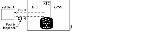
A facility loopback tests the line interface of a card and related cabling. To test, put a facility loopback on a card and use a test set to run traffic over the loopback. A successful facility loopback eliminates the line interface of the card or cabling plant as the cause or potential cause of a network problem. In the ONS 15327 system, the Mechanical Interface (MIC-28-3-A or MIC-28-3-B) card contain ports for DS-1 or DS-3 traffic. Figure 12-10 shows a facility loopback on an XTC-14 or XTC-28-3 card.
Caution
Figure 12-10 The facility loopback process on an XTC card
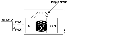
A hairpin circuit brings traffic in and out on a DS-N port instead of sending the traffic onto the OC-N. A hairpin loops back only the specific STS or VT circuit and does not cause an entire OC-N port to loop back, which would drop all traffic on the OC-N port. The hairpin allows you to test a circuit on nodes running live traffic.
Figure 12-11 The hairpin circuit process on an OC-N card
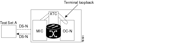
A terminal loopback tests a circuit path through the XTC card and as it loops back from the line card being tested. Figure 12-12 shows a terminal loopback set on an OC-N card. The test-set traffic comes in on the MIC card DS-N ports and goes through the XTC card to the OC-N card. The terminal loopback on the OC-N card turns the signal around before it reaches the line interface and sends it through the XTC card to the MIC card. This test verifies that the XTC cross-connect circuit paths are valid, but does not test the line interface on the OC-N card. To test the line interface on an OC-N card, connect an optical test set to the OC-N card ports and perform a facility loopback or use a loopback or hairpin on a card that is farther along the circuit path.
Figure 12-12 The terminal loopback process on an OC-N card
12.10 Network Test Procedures
Facility loopbacks, hairpin circuits and terminal loopbacks are often used together to test the circuit path through the network or to logically isolate a fault. Performing a network test at each point along the circuit path systematically eliminates possible points of failure. This example tests an XTC circuit on a two-node bidirectional line switched ring (BLSR). Using a series of facility loopbacks, hairpin circuits, and terminal loopbacks, the path of the circuit is traced and the possible points of failure eliminated.
A logical progression of five network test procedures apply to this scenario:
1.
2.
3.
4.
5.
Note
12.10.1 Perform a Facility Loopback on a Source XTC Card
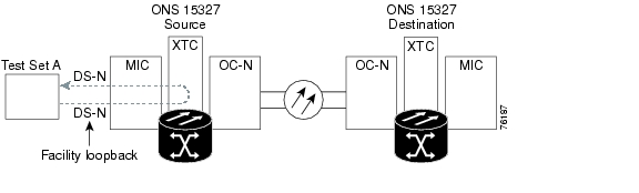
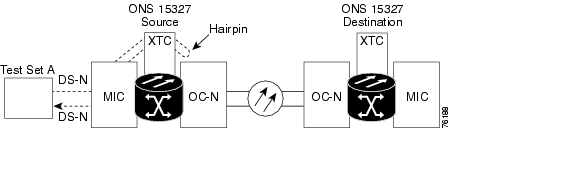
The first test is a facility loopback test performed on the first active card in the network circuit; in this example, the test is routed through the MIC card and performed on the XTC card in the source node. Completing a successful facility loopback on this card eliminates the cabling, MIC card, and XTC card as possible failure points.
Figure 12-13 Facility loopback on a source XTC card
Caution
Note
Procedure: Create the Facility Loopback on the Source XTC Card
Step 1
Step 2
Note
Step 3
Procedure: Test the Facility Loopback
Step 1
Step 2
Step 3
Step 4
Procedure: Test the DS-N Cabling
Step 1
Step 2
Step 3
Step 4
a.
b.
c.
Step 5
Procedure: Test the XTC Card
Step 1
Step 2
Step 3
a.
b.
Step 4
Step 5
Procedure: Test the MIC Card
Step 1
Step 2
Step 3
a.
b.
Step 4
12.10.2 Perform a Hairpin Circuit on a Source Node XTC Card
The second loopback test is a hairpin circuit performed on the first XTC card in the network circuit. A hairpin circuit uses the same port for both source and destination. Completing a successful hairpin through this card eliminates the possibility that the source XTC card is the cause of the faulty circuit.
Figure 12-14 Hairpin circuit on a source node XTC card
Note
Procedure: Create the Hairpin Loopback Circuit on the Source Node
Step 1
•
•
•
Step 2
Step 3
Step 4
Procedure: Test the Hairpin Loopback Circuit
Step 1
Step 2
Step 3
a.
b.
Step 4
Procedure: Test the Alternate Source XTC Card
Step 1
Caution
Note
Step 2
Step 3
a.
b.
Step 4
Procedure: Retest the Original Source XTC Card
Step 1
Step 2
Step 3
a.
b.
c.
d.
Step 4
a.
b.
12.10.3 Perform a Hairpin on a Destination Node XTC Card
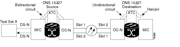
The third test is a hairpin circuit on the XTC card in the destination node. To perform this test, you must also create a bidirectional circuit from the source MIC card to the source OC-N node in the transmit direction. Creating the bidirectional circuit and completing a successful hairpin eliminates the possibility that the source and destination OC-N cards, the source and destination XTC cards, or the fiber span is responsible for the faulty circuit.
Figure 12-15 Hairpin on a destination node XTC card
Procedure: Create the Hairpin Loopback Circuit on the Destination Node XTC Card
Step 1
Step 2
Step 3
Note
For example in a typical east-to-west slot configuration, a slot 1 (east) OC-N card on the source node is one end of the fiber span, and the slot 2 (west) OC-N card on the destination node is the other end.
Step 4
Step 5
Procedure: Test the Hairpin Loopback Circuit on the Destination Node XTC Card
Step 1
Step 2
Step 3
a.
b.
Step 4
Procedure: Test the Alternate Destination XTC Card
Step 1
Caution
Note
Step 2
Step 3
a.
b.
Step 4
Procedure: Retest the Original Destination XTC Card
Step 1
Note
Step 2
Step 3
a.
b.
c.
d.
Step 4
a.
b.
12.10.4 Perform a Terminal Loopback on a Destination XTC Card
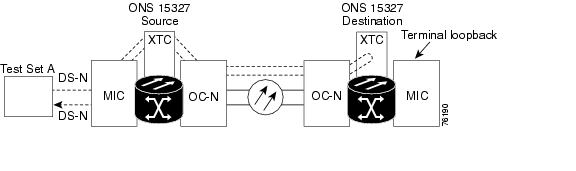
This test is a terminal loopback performed on the fourth line card in the circuit. In the following example, the XTC card in the destination node is tested. First, create a bidirectional circuit that starts on the source node DS-N port and terminates on the destination node DS-N port, then proceed with the terminal loopback test. Completing a successful terminal loopback to a destination node XTC card port verifies that the circuit is good up to the destination XTC.
Figure 12-16 Terminal loopback on a destination XTC card
Caution
Procedure: Create the Terminal Loopback on a Destination XTC Card
Step 1
•
•
Step 2
Step 3
Step 4
Note
Note
Step 5
Procedure: Test the Terminal Loopback Circuit on the Destination XTC Card
Step 1
Step 2
Step 3
Step 4
Procedure: Test the Destination XTC Card
Step 1
Step 2
Step 3
a.
b.
c.
12.10.5 Perform a Facility Loopback on a Destination XTC Card
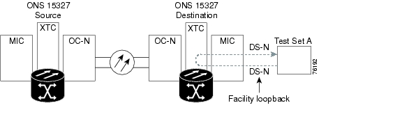
The final test is a facility loopback performed on the last port in the circuit, in this case the XTC card in the destination node. Completing a successful facility loopback on this card eliminates the possibility that the destination node cabling, MIC card, or line interface is responsible for a faulty circuit.
Figure 12-17 Facility loopback on a destination XTC card
Caution
Note
Procedure: Create the Facility Loopback on a Destination XTC Card
Step 1
Step 2
Note
Step 3
Procedure: Test the Destination Facility Loopback
Step 1
Step 2
Step 3
Step 4
Procedure: Test the DS-N Cabling
Step 1
Step 2
Step 3
Step 4
a.
b.
Step 5
Procedure: Test the XTC Card
Step 1
Step 2
Step 3
a.
b.
Step 4
Procedure: Test the MIC Card
Step 1
Step 2
Step 3
a.
b.
Step 4
12.11 Creating Diagnostic Files
When working with ONS 15327 customer support, you may need to record system information to a file and send it to technical personnel for diagnosis.
Procedure: Create a Diagnostic File
Step 1
Step 2
Step 3
Step 4
Step 5
Step 6
Step 7
12.12 Optic Fiber Cleaning
You can clean the optic fiber connected to an ONS 15327 node according to local site practice or by following the procedures below.
Warning
Note
Procedure: Clean Fiber Connectors and Adapters with Alcohol and Dry Wipes
Step 1
Step 2
Step 3
Step 4
Step 5
Step 6
Step 7
Note
Procedure: Clean Fiber Connectors with Cletop
Step 1
Step 2
Step 3
Step 4
Step 5
Step 6
Step 7
Note
Procedure: Clean the Fiber Adapters
Step 1
Step 2
Step 3
Step 4
Step 5
12.13 Power Down the ONS 15327
The following procedure describe how to power down a Cisco ONS 15327.
Warning
Caution
Note
Procedure: Power Down the ONS 15327
Step 1
Step 2
a.
b.
Note
Step 3
a.
b.
Repeat until no circuits are displayed.
Step 4
a.
b.
Repeat until no protection groups are displayed.
Step 5
a.
b.
Repeat until no SDCC Terminations are displayed.
Step 6
a.
b.
Step 7
Step 8
Step 9
Step 10
Step 11
Step 12
Step 13
![]()
![]()
![]()
![]()
![]()
![]()
![]()
![]()
Posted: Mon Feb 25 05:43:13 PST 2008
All contents are Copyright © 1992--2008 Cisco Systems, Inc. All rights reserved.
Important Notices and Privacy Statement.