|
|

Table Of Contents
2.2.5 Graphical User Interface Types
2.2.7 List of Possible Network Element IP Addresses
2.2.8 Configuration Download and Upload
2.2.9 Software and Firmware Download
2.2.11 Alarm and Event Notifications Presentation
2.2.12 Presentation of Performance Data
2.2.13 Management Configuration
2.2.17 Alarm and Event Filtering Configuration on Network Element
2.2.18 SDH Ports Configuration
2.2.19 PDH Ports Configuration
2.2.20 MSP and SNCP Configuration
2.2.21 SDH Synchronization Configuration
2.2.22 LAN Ports Configuration
2.2.23 WAN Ports Configuration
2.2.24 Test Loops Configuration
2.2.25 Cross Connect (XC) Configuration
Software Description
This section gives an overview of the Cisco Edge Craft with its features.
2.1 Introduction
Cisco Edge Craft is used to get one, single network element at the time into operation. Cisco Edge Craft can only present and work on information that are stored on the network element. A user must be logged onto Cisco Edge Craft graphical user interface (GUI) for it to function. The GUI present alarms as long as Cisco Edge Craft is connected to the network element. Performance data can be loaded from the network element and presented.
The Cisco Edge Craft presents the current (a snapshot) situation on the network element, and has very little added value functions apart from the functions on the network element.
Cisco Edge Craft is a single user system. It is a standalone application running on Windows platform or Solaris platform.
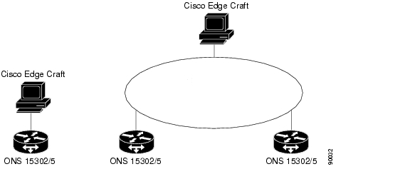
Cisco Edge Craft is a totally self contained product. It is not dependent on any other system to be able to perform its tasks. The laptop or a PC, at which Cisco Edge Craft is running, can be attached to the network element directly through the management port or through a LAN, Figure 2-1.
Figure 2-1 Cisco Edge Craft Connection Possibilities
It can co-exist together with other management products from Cisco. The SNMP Agent used by Cisco Edge Craft for communication with the network element, handles multiple SNMP Managers.
Table 2-1 displays the capabilities of the Cisco Edge Craft.
2.2 Product Features
Some of the feature listed here are only applicable to Cisco Edge Craft if the feature is available on the network element. In the remaining part of this chapter, Cisco Edge Craft is called "the system".
2.2.1 Network Element Access
The system communicates with the network element through the embedded SNMP Agent. To establish this communication line the network element must have been assigned an IP address. In situations where assignment has not been done a separate communication line on the serial port is used to perform the assignment of the IP address and other related parameters.
2.2.2 Information Model
The system has its own internal representation (information model) of the network elements. This is an object-oriented model and is identical to the information model used by all products in the Cisco Family.
2.2.3 Single User
Only one user can be logged onto the system at the time.
2.2.4 Single Network Element
The system can only communicate with one network element at the time. The user closes the connection with one element before connecting to a new network element.
2.2.5 Graphical User Interface Types
The GUI presents the network element in accordance with the information model and has no knowledge about the SNMP MIBs used by the embedded Agent.
GUI cannot be customized by the user.
The system has two different types of graphical user interfaces (GUI).
2.2.5.1 Network Element topology Browser (NETB)
A hierarchical presentation of the managed objects in the network element.
2.2.5.2 Custom GUI to Support a Specific System Feature
A GUI developed to support a specific task/function.
2.2.6 No Persistency
The system has no persistent storage of operations and notifications.
2.2.7 List of Possible Network Element IP Addresses
The system stores the IP address of the already accessed network elements. The operator can choose the IP address of the current network element in the start up window for the system.
2.2.8 Configuration Download and Upload
The system can initiate upload of the complete configuration from one network element and store it on the local or a remote computer. The remote computer is identified by its IP address.
The system can initiate download of the complete configuration from a local or remote computer to the network element. The remote computer is identified by its IP address.
The uploaded configuration can not be edited.
2.2.9 Software and Firmware Download
The system can initiate download of software and firmware onto the network element. The location of the software and firmware can either be on the same computer as the system is running on, or on a remote computer. The remote computer is identified by its IP address and both the local and remote computers must be TFTP servers.
The restart of the equipment that uses new downloaded software/firmware can be scheduled.
2.2.10 User Access
The system supports user authentication through user identification (community string).
Initial access of the network element is through public access.
2.2.11 Alarm and Event Notifications Presentation
The system presents all alarms and events that are generated while the user is logged onto the system. The alarms are presented in a tabular view. If the received traps from the network element can not be mapped to an alarm or an event, the trap is still presented to the operator.
The system presents the alarm history stored on the network element. The alarm history is presented in a tabular view.
2.2.12 Presentation of Performance Data
The system has no analysis of performance management data.
The user can read the current registered performance data on the network element, get it presented in a GUI, and copy it to file. The file can be read or edited in any tool, for example Microsoft Excel.
Supported performance data are: G.826, MIB-II (RFC1213) and RMON counters.
2.2.13 Management Configuration
The system supports configuration of the DCN management traffic settings.
2.2.14 Physical Inventory
The physical inventory gives an overview of the physical installed parts on the network element and the currently running software or firmware. Eventual downloaded not yet activated software and firmware packages are also presented.
2.2.15 Logical Inventory
The logical inventory gives an overview of the managed entities that the network element consists of. The logical entities may concur with the physical parts, but not necessarily.
2.2.16 Global Settings
The network element has some configurations that are not related to the user traffic of the network element. These are parameters like location, owner, time server, LED settings, power modules, etc.
2.2.17 Alarm and Event Filtering Configuration on Network Element
The alarm reporting from some managed entities on the network elements can be filtered out.
2.2.18 SDH Ports Configuration
The system supports configuration of the SDH ports. The SDH ports have two main configuration areas.
•
Properties of the ports. The properties can be viewed and edited.
•
2.2.19 PDH Ports Configuration
The system supports configuration of PDH ports properties. The properties can be viewed and edited.
2.2.20 MSP and SNCP Configuration
The system supports configuration of MSP and SNCP set-up, that means view, create, modify, and delete.
2.2.21 SDH Synchronization Configuration
The network element can have more than one synchronization source for the SDH traffic. The sources are prioritized. The system helps the user in the set-up of these rules.
2.2.22 LAN Ports Configuration
The system supports configuration of LAN ports properties. The properties can be viewed and edited.
2.2.23 WAN Ports Configuration
The system supports configuration of WAN ports properties. The properties can be viewed and edited. The system also supports configuration of WAN bandwidth.
2.2.24 Test Loops Configuration
The system supports configuration of test loops.
2.2.25 Cross Connect (XC) Configuration
The system supports cross connection management for the SDH ports. The XCs can be set, deleted, updated. Two supported XC's are:
•
•
2.2.26 Bridge Configuration
The system supports the set-up of the bridge.
2.2.27 VLAN Configuration
The system supports configuration of VLAN, that means, create, remove, and update VLANs.
2.2.28 Security
The security of Cisco Edge Craft is based on the SNMP v.1 security, that means community string.
2.2.29 Data Communication
Cisco Edge Craft can communicate with the network elements
•
•
•
2.2.30 Reliability
This section lists the reliability requirements and know bugs on the system.
Redundancy
One or more Cisco Edge Craft user can be connected to the same network element at the time if the network element is connected to a LAN, but they will have no knowledge of each other.
Bugs
Known bugs are presented with a workaround in the Release Notes.
2.2.31 Maintenance
Debugging and system logging are realized through log4j, open source code.
Debugging
•
•
•
System Logging
•
•
•
New Releases and Patches
The new releases or patches are available for download from the Support pages on http://www.cisco.com.
![]()
![]()
![]()
![]()
![]()
![]()
![]()
![]()
Posted: Fri Sep 14 12:08:08 PDT 2007
All contents are Copyright © 1992--2007 Cisco Systems, Inc. All rights reserved.
Important Notices and Privacy Statement.