|
|

Table Of Contents
1.1 Installation of Cisco Edge Craft
1.1.1 Uninstall Cisco Edge Craft
1.1.2 Commissioning of IP Address via VT100 Interface
1.1.4 Setting up the element for IP unnumbered, overview
1.1.5 Set up Connection to a Network Element
1.1.6 Configuration of VT100 Terminal
1.3 Commissioning Wizard - Step By Step
1.3.1 Opening The Commissioning Wizard
1.3.5 Expected Service Modules
Starting the Cisco Edge Craft
1.1 Installation of Cisco Edge Craft
This section describes how to install the Cisco Edge Craft and how to start the VT100 terminal.
Step 1
Insert the Cisco Edge Craft Software CD in desired drive on target PC.
Note
Step 2
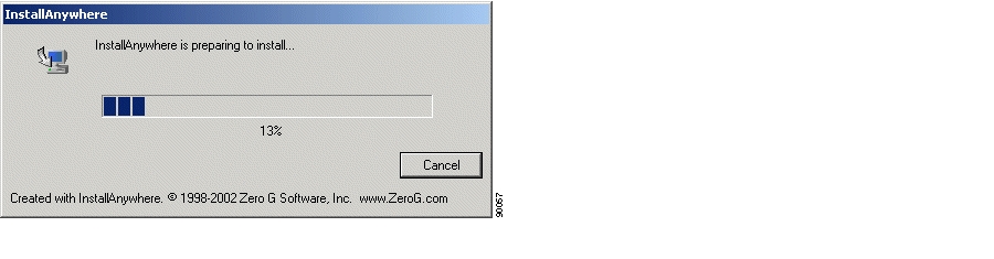
Figure 1-1 Install Shield preparing Installation Wizard
.
Step 3
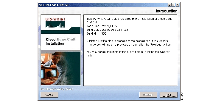
Figure 1-2 Install Wizard - Introduction
1.1.1 Uninstall Cisco Edge Craft
Select Start>Programs>Cisco Edge Craft>unistall and follow instructions given on screen.
or:
Select Start>Settings>Control Panel>Add/Remove Programs.
1.1.2 Commissioning of IP Address via VT100 Interface
A local terminal with VT100 emulation is required during the first commissioning of the network element in order to set up the necessary communications parameters enabling access to the element via Cisco Edge Craft over the Management Port. After the first commissioning, the VT100 interface can be used for modifying the communications parameters and perform some status checks of the network element. The VT100 interface is password protected.
1.1.2.1 Commissioning of IP Address via VT100 Interface
ONSCLI is a line-oriented ASCII-based management interface embedded in the Cisco network element. The ONSCLI is accessed via the VT100-port. The serial connection communications parameters are fixed:
•
•
•
•
•
VT100 terminal codes are used.
The VT100-port (Console port) for the Cisco network element is provided using a RJ-45 connector. The cable for connecting the VT100-port to the serial-port on the PC can be provided, Table 1-1.
Table 1-1 CLI Connector Pinout (RJ-45 to DS-9)
Pin 1
GND
Pin 5
NC
Pin 2
Tx
Pin 2
Rx
Pin 3
Rx
Pin 3
Tx
Pin 4
NC
Pin 5
NC
Pin 6
CTS
Pin 8
CTS
Pin 7
NC
Pin 8
RTS
Pin7
RTS
Note
Invoke ONSCLI
Step 1
Step 2
Step 3
Figure 1-3 Logon Window
.
Step 4
Figure 1-4 Start Window
Step 5
Step 6
>ONSCLI--------------------------------------------------ONS 15305 Command Line Interface--------------------------------------------------Enter ONSCLI password: ******ONSCLI>Step 7
IP-Configuration(Management-Port):Show-Current-Alarms:Community-handler:Exit:It is sufficient to type leading characters of the command name to avoid ambiguity - the same applies to keywords.
Note
The management port IP address is a compulsory parameter, and must be specified by you. All the other parameters (except default gateway) are defaulted to pre-defined values if they are not specified.
1.1.2.2 Configure Community-Handler
Note
The following example shows how to set community for a default user. If setting community for a specific user, the corresponding IP address must be entered instead of 0.0.0.0
ONS 15305
Step 1
Step 2
Step 3
Step 4
Add: Add Community entryEdit: Edit Community entryRemove: Remove Community entryShow: Show Community entryExit:ONSCLI>Community-handler\Step 5
Step 6
MANAGER: 0.0.0.0COMMUNITY: publicACCESS: superTRAPS: disableONSCLI>Community-handler\ONS 15302
Factory pre-configured community:
Manager: 0.0.0.0Community: publicAccess: SuperTraps: DisabledThis is an insecure community, which enables all managers regardless of the IP-address for the SNMP manager to access the device with the community string public.
To add your own community string you can use the following command:
Step 1
Step 2
1.1.2.3 Assign an IP Address
ONS 15302
The ONS 15305 supports remote management solutions by means of Telnet and SNMP. The possibilities that regard to connectivity can be rather advanced for the ONS 15305, so the only explained solution in this document is when directly connected the management-port (MNGT). For more information refer Cisco EdgeCraft User Guide and the ONS 15305 Installation and Operations Guide.
To achieve one of the above mentioned management solutions it is necessary to assign an IP-address, subnet-mask and if required, a default-gateway address must be defined.
System Mode
In ONS 15305 R2.0 an additional management mode, system mode, is added. System mode has two options IP and IPUNNUMBERED.
Prior to configuring the IP settings on the ONS 15305 the desirable system mode should be set, since this is a strategically choice to align with the existing design of management data communication network. By default the system mode is IP, which means that all physical indices must have a unique IP address and subnet mask. For more information refer Cisco EdgeCraft User Guide and the ONS 15305 Installation and Operations Guide.
Step 1
Step 2
Usage:System-Mode[SYSTEM-MODE=<ip|ipunnumbered>]System Mode - IP (default)
Step 1
Change management configuration, are you sure? (y/n)?Step 2
If system mode is ip the command for assigning an IP address is:
Step 3
IP-ADDRESS=193.69.136.104, SUBNET-MASK=255.255.255.0Step 4
System Mode - IP Unnumbered
Step 1
Change management configuration, are you sure? (y/n)?Step 2
Assign an IP-address:
If system mode is IP unnumbered he command for assigning an IP address is:
Step 3
IP-ADDRESS=193.69.136.104, SUBNET-MASK=255.255.255.0For most commands, if no parameters are supplied then all the current parameter values are displayed.
ONSCLI>IP-ConfigurationIP-ADDRESS: 10.0.0.1SUBNET-MASK: 255.255.255.0DEFAULT-GATEWAY: 10.0.0.254 (optional)
ONS 15302
The ONS 15302 supports remote management solutions by the means of Telnet and SNMP.The possibilities as regards connectivity can be rather advanced for the ONS 15302 so the only explained solution in this document is when directly connected the management-port (MNGT). For more information please refer the Cisco ONS 15302 Installation and Operations Guide (Release 2.0).
To achieve one of the above mentioned management solutions it is necessary to assign an IP-address, subnet-mask and if required a default-gateway address must be defined.
System Mode
In ONS 15302 R2.0 an additional management mode, system mode is added. The System mode has two options, ip and ipunnumbered.
Step 1
Step 2
Step 3
Usage:System-Mode[SYSTEM-MODE=<ip|ipunnumbered>]System Mode - IP
Step 1
Change management configuration, are you sure? (y/n)?Example 1-1 Assign an IP-address:
If system mode is ip the command for IP configuration is:
ONSCLI>Device\Management-Configuration\Management-Port\IP-Configuration
IP-ADDRESS=193.69.136.104, SUBNET-MASK=255.255.255.0.
System Mode - IP Unnumbered
ONSCLI>...\Management-Configuration\sys sys=ipunnumChange management configuration, are you sure? (y/n)?Example 1-2 Assign an IP-address:
If system mode is ipunnumbered the command for IP configuration is:
ONSCLI>Device\Management-Configuration\IP-ConfigurationIP-ADDRESS=193.69.136.104, SUBNET-MASK=255.255.255.0.1.1.2.4 Change Passwords
ONS 15305
ONSCLI>ch?Usage:
Change-Passwords
[ONSCLI -PASSWORD=<string[6:12]>][TELNET-PASSWORD=<string[6:12]>]By this command, TELNET and ONSCLI passwords can be changed. Both passwords can be changed in the same command or they can be changed one by one.
ONS 15302
ONSCLI>Security\Community-Table>ch?Usage:
Change-Passwords
[ONSCLI -PASSWORD=<string[6:12]>][TELNET-PASSWORD=<string[6:12]>]By this command, TELNET and ONSCLI passwords can be changed. Both passwords can be changed in the same command or they can be changed one by one.
1.1.3 IP Unnumbered Mode
This chapter focus on using ONS 15302 and ONS 15305 in IP un-numbered mode.
The following examples are valid for these NE releases:
ONS 15302 R2.0
ONS 15305 R2.0
In the traditional IP numbered mode, each DCC connection is an IP network, and both ends of the DCC connection have an IP address in that network.
In IP-unnumbered mode, all management interfaces of an element will have the same IP address. The DCC interfaces inherit the address of the management interface. This makes configuration of a set of elements connected via DCC simpler.
Routing between the elements will be taken care of by the OSPF routing protocol, using host routes pointing to the interfaces.
Planning the Network
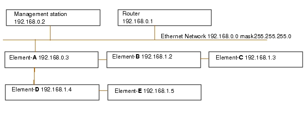
In a typical IP-unnumbered network, one element will be connected to the outside world via the management port. This is the IP unnumbered gateway. The other elements are connected to the first element via DCC channels. As an alternative to DCC channels, it is possible to use LANx ports in layer 1 mode.
Example 1Figure 1-5 Network configuration example 1
In this configuration, the network elements, except the gateway element, will have an IP address on a separate network.
The management station and the router will have a static route for all the elements in the 192.168.1.0 network via 192.168.0.3.
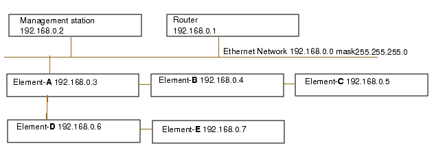
Example 2Figure 1-6 Network configuration example 2
In this example, all elements, including the gateway element, will have addresses on the same network as the other hosts on the Ethernet. The gateway element acts as an ARP proxy. That is, when a host, for instance the router, broadcasts a "who has address 192.168.0.7" on the Ethernet, the gateway element, Element-A, responds on behalf of Element-E. The following IP packets from the router to Element-E is sent to Element-A's hardware address.
1.1.4 Setting up the element for IP unnumbered, overview
Step 1
Step 2
Step 3
Step 4
Step 5
Step 6
Step 7
Step 8
Step 9
Step 10
- Add static route entries (if needed).
- Set LeakStaticRoutes (if intended).
- Set LeakExternalDirectRoutes (if intended).
Step 11
Step 12
The above steps are explained more detailed in the following sub-sections.
1.1.4.1 Connect to the element via the serial port
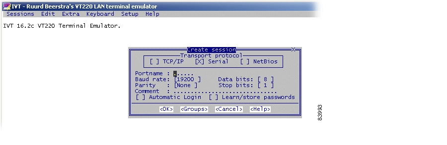
Connect the elements serial port (marked VT100) to a management station with the supplied serial cable. Use the Cisco EdgeCraft's terminal emulation program or another terminal program to connect to the elements command line interface.
1.1.4.2 Clear the configuration with ONSCLI
If the element has been configured in IP numbered mode, the configuration has to be reset.
At least, all OSPF-related entries must be removed, and all static routes, including the default route, must be deleted.
1.
2.
1.1.4.3 Setting the system mode.
When the element is unconfigured or the element has been cleared with the function "erase cdb", it initially is in IP numbered mode. Changing the system mode to IP unnumbered is done via the command line interface.
Optionally set gateway enable
If the element is the gateway element, consider setting the gateway enable to true. The effect of this variable is to create a route for the local network on the management port, and to leak this route via OSPF to the other ip unnumbered elements. Also, it ensures that static routes to gateways on the Ethernet are pointed to the correct interface.
This provides connectivity from all IP unnumbered elements in to any host on the Ethernet, see "Example 1" on page -9 or "Example 2" on page -9 configurations.
See also "Using the LeakDirectExternalRoutes variable." on page -14.
1.1.4.4 Set an IP address via ONSCLI
Use the ONSCLI to set an IP address. If this is the gateway element, a default gateway can also be set. If this is not the gateway element, a default route need not be set, as the proper routes will be configured by OSPF.
1.1.4.5 Add a user in the community table
Use the command line interface to add a line in the community table. In the ONS 15305, the community table is found in the "Community table" menu directly below ONSCLI.
Enter this command:
add manager=0.0.0.0 community=public access=super traps=disable
1.1.4.6 Connect to the element with the Management Tree
The network element must now be connected to a management station running the Management Tree using the management port. The easiest way is to use a straight unshielded twisted pair cable with RJ45 connectors in each end, and connect it directly between the element and the management station.
Configure the management station's interface to have a static IP address in the same network as the element. For instance, if the elements IP address is 192.168.1.5 and the netmask is 255.255.255.0, select for example address 192.168.1.100 for the management station (select an unused address).
Alternatively, if example 2 configuration is used, the element can be temporarily connected to the Ethernet with a cable from the management port to the switch representing the Ethernet. If this method is chosen, special care must be taken when the cable is removed after the configuration is complete. At this time, the IP traffic that till now have used the management port, is supposed to continue using the gateway element's management port.
But the other hosts, like the management station in the example and the router, will continue to send to the mac-address of the management port, now unsuccessfully.
Therefore the ARP-tables of the management station and the router have to be manually deleted.
After that, the gateway element will answer the ARP requests for the elements, and communication can continue. The ARP command is for instance arp -d 192.168.0.5 in MS Windows and the same in Solaris.
Alternatively, if a configuration like example 1 is used, the management port of the element can be connected to the Ethernet, then the management stations interface is changed to an unused address in the same IP network as the element.
ExampleThe element to be configured is 192.168.1.3, it's management port is connected to the switch representing the Ethernet. The management stations IP address is changed to 192.168.1.100.
Now we are running to IP-networks on the same Ethernet. There will be no connectivity to the router when this is going on, and the ARP table on the management station will be reset when it's IP address is changed back to the normal, 192.168.0.2, so there will be no problems with ARP tables in this case.
If the element to be configured is the gateway element (Element-A in both examples), the management port is supposed to be connected permanently, and connectivity should be ensured with no special arrangements.
1.1.4.7 Configure the DCC interfaces
Use the Management Tree to configure the DCC interfaces (alternatively, the DCC interfaces can be configured in ONSCLI).
•
•
•
•
•
Alternatively, find the dccM interface under ms under rs, and set Mode to ipOverDcc.
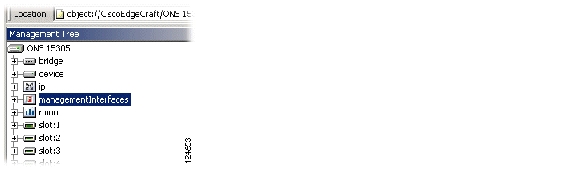
The DCC interfaces are also available in table form in managementInterfaces, DCC.
Unless the optical cables are connected to the SDH ports, and the DCC interfaces at the other ends are configured accordingly, the DCC interfaces will have OperStatus "down". This is ok for the moment, but the interfaces will have to be brought "up" for the OSPF interface configuration in a later step.
1.1.4.8 Create an OSPF area
In the Management Tree,
•
•
•
•
•
1.1.4.9 Assign the OSPF interfaces to the OSPF area
The OSPF interfaces for the DCC channels will automatically be created when the DCC channels are in "up" operational status. At this point, it is therefore necessary to connect the optical cables, where the DCC channels of the other ends of the cables are configured accordingly.
If this is not practical, it is possible to temporarily interconnect two ports on the same element, configuring the DCC channels of each port. The DCC interface will then reach "up" OperStatus, and the OSPF interfaces are visible in the AreaInterface table.
In the Management Tree,
•
•
•
•
A third possibility is to skip this step entirely, deploy the element to its final location, connect the cables and restart the element. When the element is restarted and the DCC interfaces have OperStatus up, the startup procedure will assign each OSPF-interface to the first area it finds. If this method is used, it is still necessary to enable OSPF globally for the element (see "Enable OSPF globally for the element." on page -13).
1.1.4.10 Set LeakStaticRoutes
If this is the gateway element (Element-A in the examples), the variable LeakStaticRoutes should be set to true. The default route, or any other static routes set in the element will then be announced to all the other elements in the IP unnumbered network, enabling connectivity outside the network. If this is not the gateway element, this variable should normally be set to false.
1.1.4.11 Enable OSPF globally for the element.
In the Management Tree,
•
•
•
•
1.1.4.12 Remove the management port cable.
Unless this is the gateway element, remove the management cable.
If a separate IP network was used, as in example 1, the hosts on the Ethernet should have a route to the elements via the gateway element.
Example, MS Windows
route add 192.168.1.0 mask 255.255.255.0 192.168.0.3
Example, Solaris:
route add -net 192.168.1.0/24 192.168.0.3
Delete ARP entries in the management station or the router, if appropriate, see "Connect to the element with the Management Tree" on page -12.
1.1.4.13 Verify connectivity
It should now be possible to ping the element from anywhere, and to connect Cisco EdgeCraft to the element.
All the elements should now have a route to the new element, see managementInterfaces, DCNRouter, RoutingTable.
The gateway element Element-A, should now answer ARP requests for the new element, see
Element-A's ArpProxy table found under management interfaces, DCNRouter.
1.1.4.14 Using the LeakDirectExternalRoutes variable.
Consider one of the example networks. If a management station is connected to any element in the network, for example Element-E, and the management station's IP-address is configured with a compatible IP address, connectivity to the first element is enabled.
If additionally the LeakDirectStaticRoutes in Element-E is set to "enabled", the direct route to the workstation is announced through OSPF to the other elements in the network, enabling connectivity between the directly connected workstation and all the elements in the IP unnumbered network.
A direct static route is created when the element receives an ARP-request on the management port.
1.1.4.15 Connectivity without OSPF
For the first elements behind the IP-unnumbered gateway, Element-B and Element-D in the above examples, OSPF is strictly not necessary to enable connectivity. A simple routing protocol called IPCP (IP Control Protocol) that works over PPP, will ensure connectivity to neighboring elements. The router or the management station in the examples will be able to connect to Element-B and Element-D without OSPF, but a static route in Element-B and Element-D is necessary.
Consider also a situation with many CPE (Customer Premises Equipment) elements connected to one node at the edge of the network. OSPF can be turned off on each of the CPE elements, the neighbor has LeakDirectExternalRoutes turned on. This will reduce the number of nodes running OSPF, and therefore also the OSPF traffic.
1.1.4.16 Changing the IP address
To change the IP address of an element, the global OSPF must first be turned off using the Management Tree, variable AdminStatus in OSPF. After that, the IP address has to be changed via ONSCLI using the serial cable. Alternatively, the IP address could be changed via the Management Tree, if routes are in place to cover both addresses. After that, Cisco EdgeCraft has to be reconnected using the new address.
1.1.5 Set up Connection to a Network Element
The purpose of this section is to describe the tasks involved in setting up a connection between the Craft Terminal and any network element from Cisco. See also the "Commissioning of IP Address via VT100 Interface" section.
1.1.5.1 Start the Cisco Edge Craft Application on your Computer
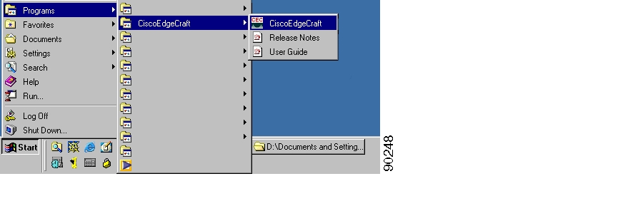
Step 1
Figure 1-7 Starting Cisco Edge Craft
Step 2
Step 3
Step 4
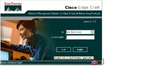
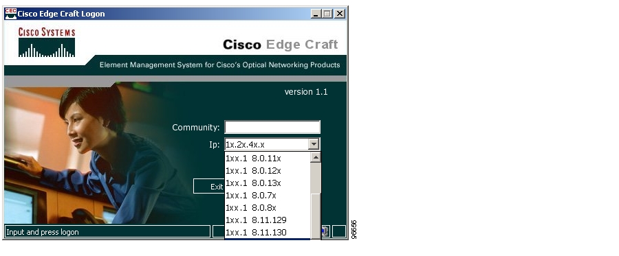
Figure 1-8 Selection of IP Address - Logon Window
.
The system adds the selected IP address to the logon window. You can also fill in the IP address manually.
Step 5
Community access levels:
The network element supports three community access levels
•
•
•
Step 6
You can now browse the network element topology and perform the required management tasks.
1.1.5.2 Invalid Community String
If the community string is invalid, access to the network element is not granted and an error message is presented.
1.1.5.3 Non-existent IP Address
The IP address given by you manually or selected by you in the list, is not reachable/non-existent or does not belong to an Cisco network element. The system gives an error message and asks for a new IP address.
1.1.6 Configuration of VT100 Terminal
The VT100 terminal can be launched from both the Cisco Edge Craft desktop and the logon window. You can change the terminal Software to be launched.
Figure 1-9 VT 100 available from Cisco Edge Craft Desktop
This is done by editing the VT 100 path description in the ExternalApplications.xml file, found in the folder: installdir\CISCOEDGE CRAFT\res\config\
Example of the ExternalApplications.xml:
<?xml version="1.0" encoding="ISO-8859-1"?>
- <ExternalApplications>
<vt100 file="./external/IVT_VT220_Telnet/ivt.exe" />
<exec file="rundll32 url.dll,FileProtocolHandler" />
<web file="rundll32 url.dll,FileProtocolHandler" />
<help file="rundll32 url.dll,FileProtocolHandler" params="./res/help/OL-5383-01.pdf" />
<releasenotes file="rundll32 url.dll,FileProtocolHandler" params="./res/help/CECrn12.pdf" />
</ExternalApplications>
1.2 Commissioning Wizard
This section describes the workflow of a Cisco network element basic set-up using the Commissioning wizard. The Commissioning wizard is a user-friendly option to provide guidance for common configuration tasks of a Cisco network element.
1.2.1 Introduction
Cisco's definition of Commissioning is that the network element is configured from scratch and is to be installed in a network for the first time.
Even though the wizard is primarily meant to cover first time installation, you may use it to change software configuration at a later stage or maybe just as a step-wise status of your configurations.
Note
Note
1.2.2 Before You Start
Please read through the different prerequisites listed in this section.
1.2.2.1 Network Element Access And Permissions
Make sure you are assigned sufficient permissions to perform the required tasks. For CEC it is mandatory to have SNMP "super" (refer initial setup) rights to configure all parameters available in wizard. Otherwise, if just permission to write, you will not be able to change or add users in the community table.
1.2.2.2 Initial set-up
All SNMP based network elements within the Cisco product portfolio require initial configuration via VT100 emulating software (for example HyperTerminal). Enclosed in box there is a special cable to connect a COM-port on a PC to VT100 port on the device. As a minimum, two configuration tasks needs to performed via local CLI, the management port need an IP address and the community table must have an instance to enable SNMP access.
Further "how to" are explained in the Quick Reference Guide provided in paper format together with HW.
1.2.2.3 TFTP server
The TFTP server must be installed, configured and accessible to the network element and the Cisco EdgeCraft prior to running the wizard. This server may be any 3rd party TFTP server running on any computer in your network, but the CEC built-in server is recommended, as it provides all the features required by the Cisco EdgeCraft to initiate and perform a user-friendly file transfer. The Cisco EdgeCraft must be aware of the relevant TFTP server attributes (IP address, optionally default input/output directories (TFTP-root)). This is required for the system to initiate file downloads and uploads during:
•
•
•
1.2.2.4 Time protocol
The network elements support automatic NE clock adjustments via RFC868 Time Protocol. If an external Time Protocol server is used, it must be installed, configured and accessible to the network element prior to running the Wizard.
There are various Time Protocol servers available, but following this URL web site provide a freeware Server, which can be used: http://www.bttsoftware.co.uk/
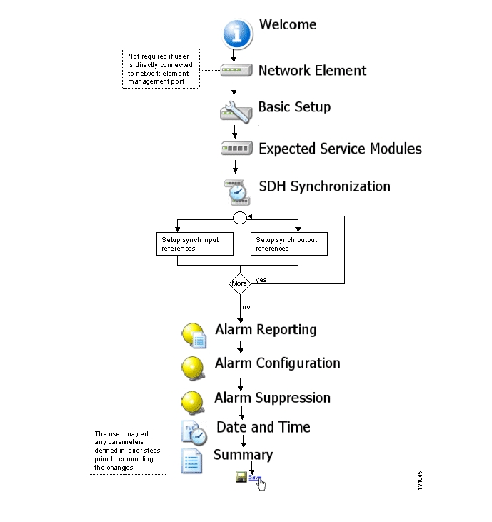
1.2.3 Basic flow
Figure 1-10
Commissioning wizard - Basic flow
1.3 Commissioning Wizard - Step By Step
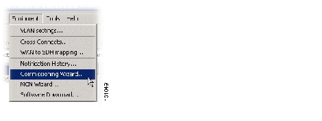
1.3.1 Opening The Commissioning Wizard
Step 1
Figure 1-11 Equipment menu
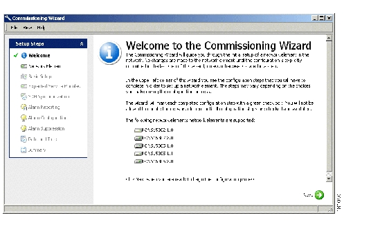
1.3.2 Welcome
Please read the introduction found in the appearing Welcome window (see figure below).
Figure 1-12
Commissioning wizard- Welcome window
Step 2
1.3.3 Network Element
This step lists the current configuration
Figure 1-13
Example of Current Configuration
Step 1
Step 2
1.3.4 Basic Setup
In this step you define the privileges of the SNMP users, and allows you to input a network element description. The order of the steps is not significant.
1.3.4.1 Network Element Information
The system presents the current network element instance description (default: blank text fields).
Figure 1-14 Network element information
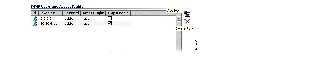
1.3.4.2 SNMP Users And Access Rights (Community Table)
In the Basic Setup windows you can also define the CEC managers that are allowed to access the network element. The system also presents the currently defined SNMP users defined in the network element.
Figure 1-15 SNMP Community table
Step 1
Step 2
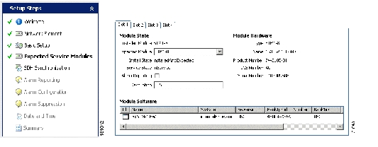
1.3.5 Expected Service Modules
In this step you set up the slots of the network element to accept their designated plug-in modules. See the "4.11.1 View Slot" section on page 4-85 for details on slot management.
Note
The system presents the current slot configurations. The slot attributes available for presentation are:
Figure 1-16
Example of current slot configuration
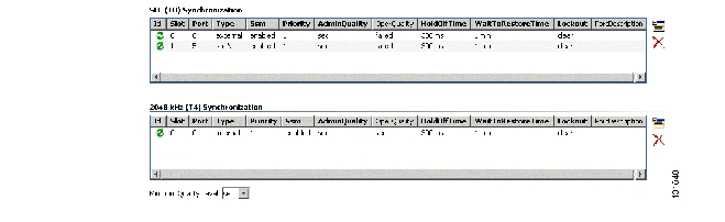
1.3.6 SDH Synchronization
In this step you set up the reference sources for the network element built-in SDH Equipment Clock (SEC) and the network element synchronization output reference signal. See the "4.6.1 SDH Synchronization" section on page 4-38 for details.
Figure 1-17
Example - current synchronization status
You can read or edit (create, delete, modify) the following synch interfaces:
•
•
•
1.3.6.1 Edit the SEC (T0) Synchronization
The synchronization source alternatives are:
•
•
•
•
1.3.6.2 ONS 15305
Step 1
1.3.6.3 ONS 15302
Step 1
1.3.6.4 Edit 2048 kHz Output (T4) Synchronization
Note
Step 1
See the "4.6.1 SDH Synchronization" section on page 4-38 for more details.
1.3.7 Alarm Reporting
In this step you configure the base unit alarm reporting enable/disable. Power modules are considered as a part of base unit.
Figure 1-18 Alarm Reporting
Note
The system presents the standard mode alarm configuration settings.
You can edit the following standard alarm configuration:
1.3.7.1 Power Module Alarms
Power module alarm settings for up to two power modules. (ONS 15305 only).
Figure 1-19 Alarm reporting - power modules
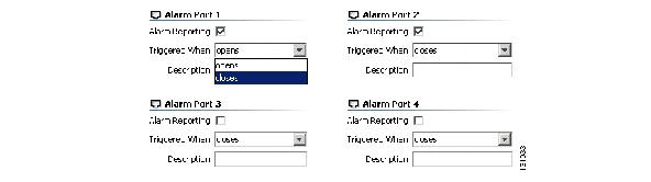
1.3.7.2 Alarm Ports
Alarm ports (4 external alarm input ports) setup.
Figure 1-20
Alarm reporting - external alarm input ports
1.3.7.3 Master Alarm Reporting
Figure 1-21
Master alarm reporting
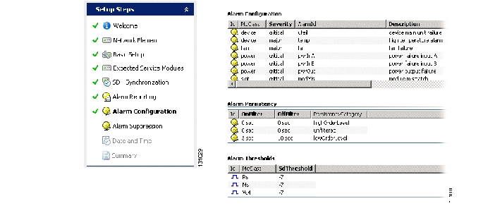
1.3.8 Alarm Configuration
This step makes it possible for an operator to modify default settings of severity, description, threshold and suppression of alarms. The following configuration choices is presented by the system:
Figure 1-22
Overview - alarm configuration choices
1.3.8.1 Alarm Configuration (Severity List)
1.3.8.2 Alarm Persistency
Alarm persistency defines how long time an alarm has to be stable until the network element will generate an alarm notification, or how long time an alarm situation must have ceased until the network element will generate an alarm cleared notification. Persistency is configured separately for alarm and alarm clear situations, and is implemented by the two filters highorderlevel and loworderlevel:
1.3.8.3 Alarm Thresholds
Some alarms are generated when a performance measurement crosses a predefined threshold. In the Cisco network elements, this threshold is configured, quality measurements on the SDH frames are associated with alarm threshold according to the listing below:
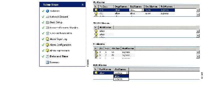
1.3.9 Alarm suppression
The alarm suppression is invoked per alarm instance or per class/group of alarms.
Figure 1-23 Example - alarm suppression
1.3.9.1 VC Alarms
1.3.9.2 TU/AU Alarms
Table 1-15 Alarm suppression - TU/AU
AisAlarms
Suppress or allow AIS alarms to be reported.
1.3.9.3 E1 Alarms
1.3.9.4 AUX Alarms
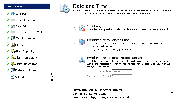
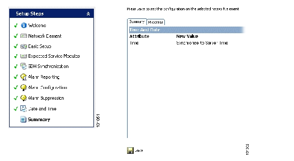
1.3.10 Date And Time
Figure 1-24 Date and time - example
In this step you manually set the time and date of the network element, or set up the system for automatic time synchronization to an IETF RFC868 Time Protocol server.
The system presents the available time and date relevant attributes:
•
•
Automatic setting of time/date:
•
•
Step 1
Step 2
Step 3
Step 4
Note
The network element does not support daylight savings time (summer time). Switching between summer and winter time will be the task of the time protocol.
1.3.11 Summary
Figure 1-25 Summary report - example
When the Commissioning wizard sequence is completed you should review the configuration before committing the changes to the network element.
The wizard presents a report of all configuration changes registered to the configuration during the Commissioning wizard flow.
Review the configuration and do one of the following:
1.3.11.1 Commit Configuration
Step 1
Step 2
•
•
1.3.11.2 Result Of The Commissioning
The network element basic configuration is completed. The network element is ready to be set up for use in a network.
1.3.11.3 Basic Network Element Set-up
The connected IP address and sub-net address of the network element is defined. Site specific information is specified for the network element.
1.3.11.4 TFTP Server
The network element is ready to use a specific TFTP server for file upload/download.
1.3.11.5 Expected Service Module (ONS 15305 only)
The network element is set up and ready to receive its designated plug-in module.
1.3.11.6 SDH Synchronization
The network element T0 and T4 clocks are set up with their designated synchronization references and synchronization strategies.
1.3.11.7 Alarm Reporting
The network element alarm system is configured according to the alarm notification strategy of the network.
1.3.11.8 Time
The network element is configured to use an external time protocol server, or the time and date is set manually.
1.3.11.9 Failures And Exceptions
When committing the configuration, the system register all configuration failures and provides an error log/report at completion, specifying what went wrong, if anything.
1 Depending on network element type and version. Used for G.826 performance data and large information model attribute tables (XC matrixes etc.)
![]()
![]()
![]()
![]()
![]()
![]()
![]()
![]()
Posted: Fri Sep 14 12:06:52 PDT 2007
All contents are Copyright © 1992--2007 Cisco Systems, Inc. All rights reserved.
Important Notices and Privacy Statement.