|
|

Table Of Contents
Octal Optical S-1.1 Module, S1.1-8-LC
Octal Optical S-1.1 Module, S1.1-8-LC
16.1 Module Description
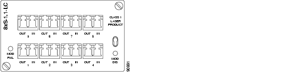
The module (see Figure 16-1) contains eight optical STM-1 interfaces that meets the S-1.1 specification in ITU-T G.957. The physical connector is a LC connector. The module also contains 8 mapper circuits and an IP switch, allowing concentration of IP traffic mapped into VC-12 container. Since the mapper circuits are connected to the matrix, the mapper circuits are global resources which means that the traffic to be terminated may come from other modules in the system.
Figure 16-1 Octal Optical S-1.1 Module, S1.1-8-LC
16.1.1 Power Consumption
The module power consumption is 25 W.
16.2 External STM-1 Interface
The eight optical STM-1 interfaces use dual fiber interface, LC style connector, one fiber in each direction, 1310nm wavelength and use single mode fiber of type 10/125 um. The optical interfaces is compatible with ITU-T 957 for S-1.1.
The interface is an optical STM-1 short haul interface, according to clause 5 ITU-T G.957 The definitions of optical parameters and reference points S and R refer to ITU-T G.957. Reference point S means transmit direction while R is the receive direction of the fibre.
16.2.1 Connector Type
The physical connector is a LC connector.
16.2.2 Optical Budget
The Optical Budget S-1.1 Interface is given in Table 16-1.
16.2.3 Compliance
The Optical S-1.1InterfaceCompliance is given in Table 16-2.
Table 16-2 Compliance Optical S-1.1Interface
![]()
![]()
![]()
![]()
![]()
![]()
![]()
![]()
Posted: Fri Sep 14 08:43:20 PDT 2007
All contents are Copyright © 1992--2007 Cisco Systems, Inc. All rights reserved.
Important Notices and Privacy Statement.