cc/td/doc/product/ong/15305/305docs
hometocprevnextglossaryfeedbacksearchhelp
PDF

Table Of Contents

Dual Optical + 21xE1 S1.1-2-LC/E1-21 Module

19.1  Module Description

19.1.1  Power Consumption

19.2  External STM-1 S-1.1 Interface

19.2.1  Connector Type

19.2.2  Optical Budget

19.2.3  Compliance

19.3  External E1 Interface

19.3.1  Connectors

19.3.2  Patch Panels

19.3.3  Compliance

19.4  Example of Cable Planning, STM-1 S-1.1 interface


Dual Optical + 21xE1 S1.1-2-LC/E1-21 Module


19.1  Module Description

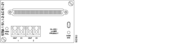
The module contains two optical STM-1 short-haul interfaces and 21 E1 interfaces. The main functions of the module are O/E- E/O conversion and SDH multi-/demultiplexing with VC-12, VC3 and VC-4 granularity of the STM-1 traffic and VC-12 mapping/demapping demultiplexing of the E1 traffic. Seethe "5.1.1  Multiplexing Structure and Mapping Modes" section on page 5-1. The module supports both transparent E1 data transmission acc. to ITU-T Rec. G.703 as well as the NT functionality of ISDN PRA according to ETSI 300 233. One high density LFH type connector is used to interface the 21 E1's and a dual fiber LC connector, one fibre in each direction, is used on the two STM1 interfaces.

19.1.1  Power Consumption

15 W.

19.2  External STM-1 S-1.1 Interface

The optical STM1 interfaces are short haul interfaces, according to ITU-T Rec. G.957, S-1.1, bi-directional transmission on two Single Mode (SM) fibres.

The module can also be used for transmission on Multi Mode (MM) fibres, see the "Example of Cable Planning, STM-1 S-1.1 interface" section.

19.2.1  Connector Type

The physical connector is a LC connector.

Figure 19-1 STM-1 S1.1-2-LC/E1-21 Module

19.2.2  Optical Budget

Table 19-1 S-1.1 Interface Optical Budget

Parameter
Value

Type of fibre: SM acc. ITU-T Rec. G.652 (See Note below)

10/125 µm

Modulation rate on optical line

155 520 kbit/s

Wavelength range

1261 - 1360 nm

Transmitter at reference point S
 

Source type

MLM

Spectral characteristics (max. RMS width)

7.7 nm

Mean launched power (max.)

-8 dBm

Mean launched power (min.)

-15 dBm

Min. extinction ratio

8.2 dB

Optical path between S and R
 

Attenuation range

0 - 12 dB

Max. tolerable dispersion

260 ps/nm

Min. optical return loss

NA

Max. discrete reflectance between S and R

NA

Receiver at reference point R
 

Min. sensitivity (BER < 1 in 1010)

-28 dBm

Min. overload

-8 dBm

Max. optical path penalty

1 dB

Max. reflectance at R

NA


Note The module can also be used for transmission on Multi Mode fibre, see the "Example of Cable Planning, STM-1 S-1.1 interface" section .


19.2.3  Compliance

Table 19-2 Optical S-1.1 Interface Compliance

Standard
Comment

ITU-T G.652

Type of optical fibre

ITU-T G.707

Optical line signal

ITU-T G.783

RX pull-in and hold range

ITU-T G.813

Optical output jitter

ITU-T G.825

Optical input jitter

ITU-T G.957

Optical spectrum

Optical output power

Optical eye diagram

Optical extinction ratio

ITU-T G.958

Input jitter measurement

ITU-T G.651

Multi Mode Fibre specification 50/125 µm

IEC/EN 60793-2-10

Optical fibres -- Part 2-10:
Product specifications - Sectional specification for category A1 multimode fibres


19.2.3.1  Optical Rx Power Monitoring

The optical input power of the Rx interface is monitored and can be read from the CiscoEdgeCraft terminal.

19.3  External E1 Interface

19.3.1  Connectors

The connector is a high density LFH connector. See the "14.2.1  32XE1 LFH - LFH Cable" section on page 14-3 for details.

19.3.2  Patch Panels

Two types of patch panels are available for patching the 21 E1's interface. See the "14.2  Patch Panels" section on page 14-2 for details.


Note When the LFH connector/Patch panels are used together with the STM-1 S1.1-2-LC/E1-21 module, only the first 21 ports are used.


Warning This interface is considered SELV cicuit. Avoid connecting this interface to TNV circuits. The cables must not run with power cables, Network cables, or any other cables wich are not connected to SELV circuits. The electrical cables must not exit the building. If cables are connected to an equipment wich contains not SELV circuits, proper insulation between the ONS15305 E1 cables interface and the other equipment interfaces must be provided.


19.3.3  Compliance

Table 19-3 Multi-Interface E1 Compliance

Standard
Comment

ETS 300 011

Impedance towards ground

Tolerable longitudinal voltage

ETS 300 126

Output signal balance

ITU-T G.703

Cable attenuation

Input reflection loss

Input port immunity against reflection

Output pulse mask

ITU-T G.783

Output jitter in the absence of input jitter

Output combined jitter

ITU-T G.823

Max. tolerable input jitter


19.4  Example of Cable Planning, STM-1 S-1.1 interface

Table 19-4 Typical Cable Parameters

Cable Loss, according to ITU-T Rec. G.957
Single Mode fibre Acc. to ITU-T G.652
Multi Mode fibre 50/125 um Acc. to ITU-T G.651
Multi Mode fibre 62.5/125 um Acc. to IEC/EN 60793-2-10

Fibre Cable Attenuation

Cable Margin (Mc)

Loss in Optical Distribution Frame

0.5 dB/km

Incl. in fibre att

Incl. in fibre att.

1.0 dB/km

3 dB

1 dB

1.0 dB/km

3 dB

1 dB

Cable Dispersion:

Maximum Chromatic Dispersion Coefficient

5.5 ps/nm*km

6 ps/nm*km

6 ps/nm*km

Modal bandwidth

-

800 MHz*km (Note 1)

500 MHz*km (Note 1)

Overall bandwidth

-

80 MHz

80 MHz


Table 19-5 Typical Link Spans

Type of fibre
Loss Limited Span
Dispersion Limited Span
Overall Link Span
Notes

Two-fibre

SM

24 km

47 km

24 km


MM 50 mm

13 km

10 km

10 km

Note 2,3

MM 62.5 mm

13 km

6 km

6 km

Note 2,3


Note Modal bandwidth for Overfilled launch (OFL).


Note Offset launch with mode-conditioning patchcord according to IEEE Std. 802.3 1998 edition.


Note By using a MM fibre like GIGAlite™ II, dispersion limited spans can be extended to 15km (50/125mm) and 9 km (62.5/125 mm) without the need of a mode-conditioning patchcord.


Centre launch with SM patch cord connected directly to the MM fibre gives potentially much higher bandwidths than the OFL bandwiths (several GHz/km) as only a few central modes are launched.

However, MM fibres can contain central index distortions, which can give rise to bandwitdh collapse with small offsets from centre . Both centre launch and offset launch with FP laser creates underfilled exictation of the MM fibre. Offset launch is less vulnerable to mode coupling distortions due to the higher number of modes beeing exited. Underfilled excitations generally gives higher bandwidths than OFL.

Recommendation

Centre launch i.e. SM patchcord from 2xS-1.1-LC, is likely to achieve transmssion distances at least as given in the table for most MM fibre cables. Use of mode conditoning cord for offset launch, is preferred when quality of MM fibre plant is unknown.


hometocprevnextglossaryfeedbacksearchhelp

Posted: Fri Sep 14 10:10:52 PDT 2007
All contents are Copyright © 1992--2007 Cisco Systems, Inc. All rights reserved.
Important Notices and Privacy Statement.