cc/td/doc/product/ong/15305/305docs
hometocprevnextglossaryfeedbacksearchhelp
PDF

Table Of Contents

Features

5.1  SDH Features

5.1.1  Multiplexing Structure and Mapping Modes

5.1.2  SOH and POH Termination

5.1.3  Cross-Connect

5.1.4  Protection

5.1.5  Performance Monitoring

5.1.6  Synchronization

5.2  IP Features

5.2.1  VLAN acc. to IEEE802.1Q

5.3  DCN Features

5.3.1  Protocol Stack

5.3.2  Management Interfaces

5.3.3  Communication Features

5.3.4  Management Security

5.4  Alarm Definitions

5.4.1  Device

5.4.2  SDH

5.4.3  LAN/ WAN

5.4.4  Miscellaneous

5.5  Physical Interface Indexes


Features


This chapter provides an overview of the features of the Cisco ONS15305.

5.1  SDH Features

5.1.1  Multiplexing Structure and Mapping Modes

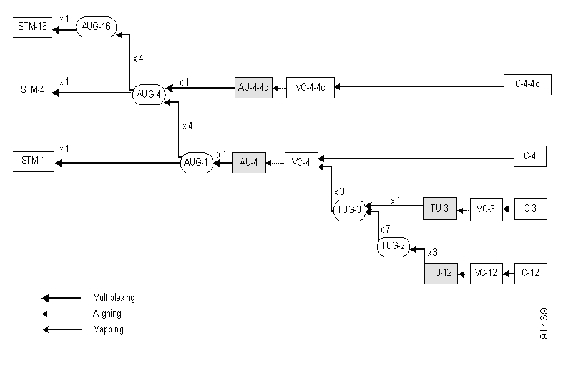
The ONS 15305 supports the multiplexing structure given in figure below. This is a subset of the possible multiplexing structures defined in ITU-T G.707 clause 6, according to ETS300147 The multiplexing is done in accordance with ITU-T G.707 clause 7.

Figure 5-1 Multiplexing Mapping Structure

The ONS 15305 support asynchronous mapping of E3 (34 368 kbit/s) signals and T3 (44 736kbit/s) signals into a VC-3 according to ITU-T G.707 clause 10.1.2, and asynchronous mapping of E1 (2 048kbit/s) signals into a VC-12 according to ITU-T G.707 clause 10.1.4.1.

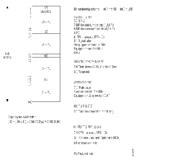
The ONS 15305 also provides a mapping scheme for transporting Ethernet traffic in a number of VC-12s. The mapping is performed in a round-robin fashion with an inverse multiplexer function. The mapping between Ethernet and SDH is performed in WAN ports that are located on the 8xSTM-1 module.

The proprietary mapping scheme used is described in Figure 5-1. It's only the mapping that is proprietary; all POH in the VC-12 is according to ITU-T G.707.

Figure 5-2 Ethernet Mapping Scheme

The total bandwidth for one WAN channel cannot be greater than 100 Mbit/s or 50xVC-12 containers, though the proprietary VC-12 mapping scheme for Ethernet, take advantage of 2,16 MBit/s in each VC-12, which means that 47xVC-12 are sufficient to transport 100MBit/sEhernet. The VC-12 k.l.m reference assignment for the Ethernet WAN port is fully flexible, and controlled in the same way as a VC-12 cross connect. The only thing, which is required and must be obtained is the order of VC's carrying Ethernet traffic between two WAN-ports.

5.1.2  SOH and POH Termination

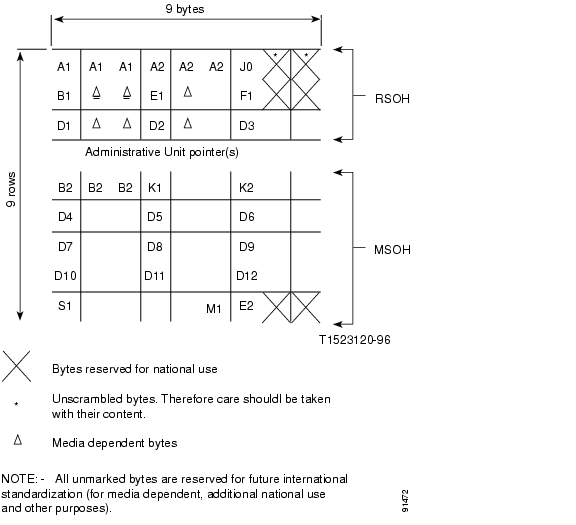
5.1.2.1  RSOH and MSOH

The ONS 15305 terminates and generates a subset of the SOH-overhead specified in ITU-T G.707
clause 9.

The SOH for an STM-1 is reproduced in the figure below.

Figure 5-3 SDH Overhead Bytes

The ONS 15305 generates and terminates the following bytes:

Table 5-1 Bytes that are Generated by the ONS 15305

Bytes
Explanation

A1, A2

Frame sync word, according to ITU-T G.707

J0

It is possible to edit both the transmitted, received and expected value of the J0 byte from the NM system.

B1

According to ITU-T G.707, shall be available as an error performance counter at the NM level.

E1

Is terminated/generated According to ITU-T G.707 and available on an output port upon request from the NM level.

F1

Is terminated/generated According to ITU-T G.707 and available on an output port upon request from the NM level.

D1-D3

Is terminated/generated According to ITU-T G.707.

B2

According to ITU-T G.707, shall be available as an error performance counter at the NM level.

K1,K2(b1-b5)

Terminated/generated according to the MSP protocol defined in ITU-T G.841. The protocol used is the one defined in clause 7.1.4.5.1, 1+1 bi-directional switching compatible with 1:n bi-directional switching.

K2(b6-b8)

Terminated/generated according to ITU-T G.707 clause 9.

D4-D12

Is terminated/generated According to ITU-T G.707.

S1

Terminated/generated according to ITU-T G.707 clause 9

M1

Terminated/generated according to ITU-T G.707 clause 9.

E2

Is terminated/generated According to ITU-T G.707 and available on an output port upon request from the NM level.

POH VC-4/VC-3 and VC-12 level

The ONS 15305 offers termination/generation of a subset of the POH bytes defined in ITU-T G.707 clause 9. The ONS 15305 terminates/generates the following POH bytes at VC-4/VC-3 level:

J1

A 16 byte frame is defined for the transmission of the Path Access Point Identifier. The format of the frame is in accordance with ITU-T G.831 clause 3 and ITU-T G.707 clause 9.

It is possible to edit both the transmitted, received and expected value of the J1 byte from the NM system.

B3

According to ITU-T G.707, shall be available as an error performance counter at the NM level.

C2

Terminated/generated according to ITU-T G.707 clause 9.

G1:

Terminated/generated according to ITU-T G.707 clause 9.

F2/F3

Not used.

H4

Payload dependent, terminated/generated according to ITU-T G.707.

K3

Not used

N1

Not used

The ONS 15305 terminates/generates the following POH bytes at VC-12 level:


V5

Terminated/generated according to ITU-T G.707 clause 9.

J2

A 16 byte frame is defined for the transmission of the Path Access Point Identifier. The format of the frame is in accordance with ITU-T G.831 clause 3 and ITU-T G.707 clause 9.

It is possible to edit both the transmitted, received and expected value of the J2 byte from the NM system.

N2

Not used.

K4

Not used.


5.1.3  Cross-Connect

The ONS 15305 implements a full non-blocking 64x64 STM1 cross connect with VC12, VC-3 and VC-4 granularity.

The cross-connect supports bi-directional cross-connections on all levels.

5.1.4  Protection

5.1.4.1  1+1 linear MSP

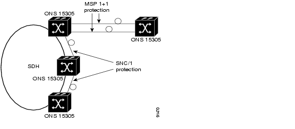
The ONS 15305 offers 1+1 linear Multiplex Section Protection (MSP). The protocol used for K1 and K2 (b1-b5) is defined in ITU-T G.841, clause 7.1.4.5.1. The protocol used is 1+1 bi-directional switching compatible with 1:n bi-directional switching.

The MSP protection is not linked to a pair of ports on the same module, ports on module 1 and 2 can protect each other and ports on module 3 and 4 can protect each other as long as they are of the same type.

Figure 5-4 Protection Scheme for the ONS 15305

5.1.4.2  SNC/I

The ONS 15305 also support SNC/I, (Sub Network Connection protection with Inherent monitoring) on both LO and HO VC's. The Application architecture supported is 1+1 unidirectional switching according to ITU-T G.841 clause 8.3.2.


Note This protection scheme is called SNCP by ETSI.


5.1.5  Performance Monitoring

The ONS 15305 offers full G.826/G.829 performance monitoring on all levels in the SDH hierarchy, including B1 monitoring in RSOH, B2 near and far end in MSOH, B3 near and far end at VC-4/VC-3 level and BIP-2 near and far end at VC-12 level.

The ONS 15305 calculates excessive error and degrade signal defects assuming Poisson distribution of errors, according to ITU-T G.826.

The excessive error defect (dEXC) is be detected if the equivalent BER exceeds a pre-set threshold of 10E-5, and is cleared if the equivalent BER is better than 10E-6, according to ITU-T G.806.

The degraded signal defect (dDEG) is detected if the equivalent BER exceeds a pre-set threshold of 10E-X, where x=6,7,8 or 9. The dDEG is cleared if the equivalent BER is better than 10E-(X+1), according to ITU-T G.806.The threshold is individual configurable for the different levels in the SDH hierarchy, from 10E-6 to 10E-9.

5.1.6  Synchronization

The ONS 15305 offers synchronization from a range of different interfaces:

STM-16

STM-4

STM-1

2MHz sync input

E1 interface configured in PRA mode

The synchronization is G.781 compliant.

Through the SETS (Synchronous Equipment Timing Source), the synchronization signals are distributed to the equipment ports.

The ONS 15305 offers a list of 5 possible synchronization sources for the T0, selection of the sync source is based upon the quality level.

The ONS 15305 supports SSM messaging on the STM-N interfaces, this is not supported on the E1 interface.

5.2  IP Features

ONS15305 supports a transparent multi-port remote Ethernet bridge as specified in IEEE 802.3. The number of interfaces is dependent of the inserted modules. The plug-in modules support 10Base-T over copper, 100Base-TX (fast Ethernet (FE)) over copper, gigabit Ethernet (GE) over fibre and a proprietary STM-1 interface for connection to the ONS15302 product.

The bridge supports the following features:

MAC switching

Static MAC entries

Support of up to 32k MAC addresses

Automatic Learning & Ageing for MAC addresses

Auto negotiation (speed/duplex)

Fixed Ethernet Port settings i.e. 10/100/1000 half/full duplex

Auto MDI/MDIX, Ethernet FE/GE interfaces

MAC Multicast

Transparent Bridging

Port-based Virtual LANs (VLANs)

VLAN by Port and VLAN by Port and Protocol

Full IEEE 802.1Q VLAN tagging compliance

Head of Line Blocking prevention

Back pressure and flow control Handling

IGMP snooping

Spanning Tree Protocol (STP) per device

Rapid reconfiguration of edge LANs in spanning trees

STP per VLAN

Mirroring Port

IEEE 802.1p priorities (Strict Policy, 4 queues)

GARP VLAN registration protocol (GVRP)

MTU Size 6144 bytes

The filtering rate of the bridge is able to operate at full wire speed. For FE-modules the maximum pps is 148 kpps for 64 byte packet size. The forwarding rate on GE connections will be limited in case of just small packets. For GE this pps is 70% of wirespeed on small packet sizes. I.e. 1015 k at 64 bytes packet size wirespeed from 100 bytes packets 1008 k pps.

BootP is used to get one IP address for the ONS 15305 under the installation process.

5.2.1  VLAN acc. to IEEE802.1Q

By default SW configuration, the ONS15305 support 802.1Q and can handle up to 4000 VLAN simultaneously. The VLAN id range available in this case are 1-4000.

If you need to activate STP per VLAN acc. to an early draft of IEEE802.1s, the maximum VLAN's are 200. The VLAN id range availability persists i.e. 1-4000.

If you need to enable multicast configuration (and IGMPsnooping) on the device the maximum number of potential VLAN's must be reduced to a number lower than 4000. Each multicast group entry reduce the maximum number of VLAN's by one (1).


Note Enabling the multicast configuration feature, will also disable part of the VLAN ingress filtering mechanisms. The consequence of this is that frames can be inserted into a neighbouring VLAN by spoofing the VLAN tag of the said frame. However, correctly tagged frames will NOT leak to the other VLANs.


5.3  DCN Features

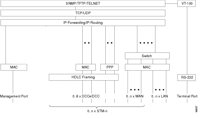
This chapter presents the ONS 15305 protocol stack, interfaces, communication functions used for management communications.

5.3.1  Protocol Stack

Figure 5-5 DCN Protocols

The following standards apply:

Table 5-2 Protocol Standards

Abbreviation
Standard

Switch

IEEE 802.1d - Media Access Control Bridges, 1998 Edition Revision (incorporating IEEE 802.1p). The requirements in chapter 2.2.3 apply.

MAC / LLC

IEEE 802.x - Information Processing Systems - Local Area Networks

PPP

RFC 1661 Point to Point ProtocolNSIF-DN-0101-001

HDLC

ISO 4335 - High-level Data Link Control (HDLC) proceduresRFC 1662 PPP in HDLC-like framing.

IP

RFC 791 - Internetwork Protocol

RS-232

EIA-232

TCP

RFC 793 - Transmission Control Protocol (TCP)

UDP

RFC 768 - User Datagram Protocol (UDP)


5.3.2  Management Interfaces

The purpose of the Management DCN is to carry management traffic between a management system and the managed devices. The management traffic pertinent to the ONS 15305 is IP carrying SNMP, TELNET and TFTP application protocols. In order to support management connectivity in any possible topology and application, the ONS 15305 supports management traffic on the following interfaces:

5.3.2.1  Management Port

The ONS 15305 has a dedicated Ethernet port for management, called the "Management Port". This port can be used for local management, e.g. connecting a craft terminal. It can also be used for connecting to a separate external management network. The management port can be turned off to avoid unauthorized local access. The management port cannot be member of a VLAN.

5.3.2.2  LAN Ports

The LAN ports are Ethernet ports used for connecting end customer IP traffic to the ONS 15305. The LAN ports can be members of VLANs which may or may not have an IP address, or they can have their own IP address. A LAN port can be used for carrying management traffic to/from the box, provided that it (or the VLAN it is member of) is assigned to an IP address. This is called IP-Inband, i.e. some of the end-user IP bandwidth is used for management traffic.

5.3.2.3  WAN Ports

The WAN ports are device internal Ethernet ports that can be mapped into one or more VC-12s of a SDH STM-n signal. The WAN ports can be members of VLANs which may or may not have an IP address, or they can have their own IP address. A WAN port can be used for carrying management traffic to/from the box, provided that it (or the VLAN it is member of) is assigned to an IP address. This is called IP-Inband, i.e. some of the end-user IP bandwidth is used for management traffic.

5.3.2.4  SDH Ports

The SDH architecture defines data communication channels (DCC) for transport of management traffic in the regenerator section (DCCR - 192 kbit/s) and in the multiplexer section (DCCM - 512 kbit/s).

The ONS 15305 supports the NSIF-DN-0101-001-R1 Draft Specification which defines IP in PPP over DCC.

The ONS 15305 also offers non-standard DCC communication that can be used in subnets of Cisco devices only. Ethernet frames are encapsulated in HDLC-like frames and sent on the DCC channel (i.e. not using CLNP and LAP-D). Both DCCR (Regenerator Section) and DCCM (Multiplexer Section) channels are supported.

Both DCC channels may be enabled on a port at a time. Activation/deactivation of DCC channels is configurable on a per port basis. The upper limit for simultaneously utilisation of DCC on the ONS15305 is:

4xDCCM and 8xDCCR channels in each slot

5.3.2.5  Local VT-100Serial Port

CLI for basic set-up of the ONS 15305. Can also be accessed through TELNET.

5.3.3  Communication Features

5.3.3.1  IP-Forwarding

The IP-Forwarding implies that the device can have multiple IP interfaces, i.e. it can be a multi-homed IP host. In addition it is able to perform forwarding of IP datagrams between the interfaces, and the routing protocols (RIP, OSPF) are available. IP-Forwarding is intended for management traffic only.

5.3.3.2  SW based IP Routing

Forwarding of IP datagrams to/from the Management Port and DCC interfaces are software based.The routing is performed by the CPU and mainly intended for management purpose.

The the following features are supported:

Address Resolution Protocol (ARP)

ARP proxy

Internet control message protocol (ICMP) Messages

Static IP routes

Routing information protocol (RIP) versions I and II

RIP subnet filtering

Open shortest path first (OSPF) version 2

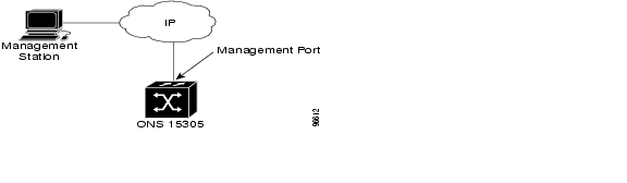
5.3.3.3  External DCN

This configuration is applicable for users connecting an IP based DCN directly to the ONS 15305 or for connecting a craft terminal. For this type of connection, the management port is used. The configuration is described Figure 5-6.

Figure 5-6 Network Configuration
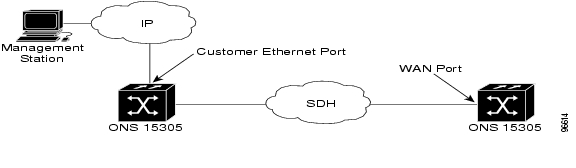
5.3.3.4  IP-Inband

IP-Inband means that LAN and WAN ports are carrying management traffic together with customer traffic. The configuration is described in Figure 5-7.

When using IP-Inband, the management traffic can be routed or switched (using VLANs). If routed, the routing is carried out in hardware (FFT) if IP-Routing is enabled. Otherwise, IP-Forwarding is used, i.e. software based .

Figure 5-7 Network Configuration
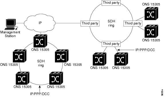
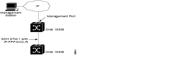
5.3.3.5  IP/PPP

IP/PPP means IP carried in PPP on the SDH DCC channel according to NSIF-DN-0101-001. Typical configurations are described by Figure 5-8 When MSP is enabled, the management traffic over DCC follows the user traffic, i.e. traffic is sent over both link (working and protecting), but received only from the active link.

Figure 5-8 Network Configuration

5.3.3.6  IP/DCC

IP/DCC is a non-standard mechanism used for conveying management information on the SDH DCC channels in a network of Cisco devices only. This mechanism can be used together with the IP/DCC-Broadcast mechanism of other Cisco devices emulating a shared media on the SDH DCC channel. The IP datagrams are encapsulated in HDLC frames before sent out on the SDH DCC.

This configuration is applicable for a user having a subnet of Cisco devices (with the ONS 15305 in the center) and an IP based DCN connected to the ONS 15305 (e.g. the management port). The configuration is described Figure 5-9.

Figure 5-9 Network Configuration

5.3.4  Management Security

The following security features applies to management communications:

5.3.4.1  CLI Access Control

Locally through VT100; User name and Password mechanisms.

Remotely Telnet; Telnet password and aditionally same mechanism as through VT100.

5.3.4.2  SNMPv1 Access Control

For each user (SNMP Community), the following can be configured:

Read , Read/Write or Super access. With Super access rights you will be allowed to configure Community table.

From which managers, in terms of IP address, SNMP requests are accepted.

5.3.4.3  Management Port Control

The Management Port can be enabled/disabled. This gives the operator control of the local access.

5.4  Alarm Definitions

The following subsections (heading relate to the managed object type) present alarms and events listed with Alarm ID, default severity and description


Note All alarm IDs with higher severity than "Warning",except "info" which is an event, are on-off alarms. Also "alarmInp (has default severity "Warning") is an on-off alarm.


5.4.1  Device

Table 5-3 Device Alarms

Alarm Id
Default Severity
Description

ufail

Critical

Device main unit failure

temp

Major

High temperature alarm

t0HoldOver

Major

T0 in holdover mode

t0Defect

Critical

T0 SETG defect

t0SyncSwitch

Warning

T0 sync switchover

t0QlFailed

Warning

T0 sync candidate in fail

t0QlDnu

Warning

T0 sync candidate received DNU

t4Squelch

Critical

T4 output squelched

inletFail

Critical

DXC inlet failure

inletBitError

Critical

DXC inlet bit error

info

Critical


rxOverflowHWFault

Warning

RX buffer overflow on LAN interface

txOverflowHWFault

Warning

Interport queue overflow on LAN interface

routeTableOverflow

Warning

Routing table overflow

resetRequired

Warning

Reset required

endTftp

Warning

TFTP session completed

abortTftp

Warning

TFTP session aborted

startTftp

Warning

TFTP session initiated

faultBackUp

Warning

Automatic switchover to backup link

mainLinkUp

Warning

Communication returned to main link

ipxRipTblOverflow

Warning

OpenGate IPX RIP table overflow

ipxSapTblOverflow

Warning

OpenGate IPX SAP table overflow

facsAccessVoilation

Warning

FACS blockAndReport statement forwarded to interface

autoConfigurationCompleted

Warning

Autoconfiguration completed successfully

forwardingTabOverflow

Warning

Layer II Forward Table overflow

framRelaySwitchConnectionUp

Warning

Connection established between Frame Relay Switch and WanGate

framRelaySwitchConnectionDown

Warning

Connection failure between Frame Relay Switch and WanGate

errorsDuringInit

Warning

Error during initialisation

vlanDynPortAdded

Warning

Dynamic VLAN port added

vlanDynPortRemoved

Warning

Dynamic VLAN port removed

rsSDclientsTableOverflow

Warning

Client table overflow

rsSDinactiveServer

Warning

Server not responding

rsIpZhrConnectionsTableOverflow

Warning

Zero Hop Routing Table overflow

rsIpZhrReqStaticConnNotAccepted

Warning

Static connection rejected, no virtual IP address

rsIpZhrVirtualIpAsSource

Warning

Virtual IP address appeared as source IP

rsIpZhrNotAllocVirtualIp

Warning

Virtual IP not allocated for source

rsSnmpSetRequestInSpecialCfgState

Warning

SET request rejected during reconfiguration

rsPingCompletion

Warning

Ping sequence completed

pppSecurityViolation

Warning

PPP security violation

frDLCIStatudChange

Warning

FR DLCI status change

papFailedCommunication

Warning

PAP failed communication

chapFailedCommunication

Warning

CHAP failed communication

rsWSDRedundancySwitch

Warning

Redundancy switchover

rsDhcpAllocationFailure

Warning

DHCP IP address allocation failed

rlIgmpTableOverflow

Warning

IGMP table overflow

rlPimTableOverflow

Warning

PIM table overflow

rlIpFftStnOverflow

Warning

IP SFFT overflow

rlIpFftSubOverflow

Warning

IP NFFT overflow

rlIpxFftStnOverflow

Warning

IPX SFFT overflow

rlIpxFftSubOverflow

Warning

IPX NFFT overflow

rlIpmFftOverflow

Warning

IPM FFT overflow

rlPhysicalDescriptionChanged

Warning

Physical description of device has changed

rlPolicyDropPacketTrap

Warning

Packet is dropped due to qos policy

rlPolicyForwardPacketTrap

Warning

Packet is forwarded based on qos policy


5.4.2  SDH

Table 5-4 SDH Alarms

Alarm Id
Default Severity
Description

SDH Port

los

Critical

Loss Of Signal

RS

lof

Critical

Loss Of Frame

exc

Major

BER excessive error rate

deg

Minor

Signal degrade (BER low)

tim

Critical

Trace Identifier Mismatch

csf

Minor

Communication Signal Fail

MS

exc

Major

BER excessive error rate

deg

Minor

Signal degrade (BER low)

csf

Minor

Communication Signal Fail

ais

Minor

Alarm Indication Signal

rdi

Minor

Remote Defect Indication

msp

Critical

MSP signalling problem

switchToProt

Warning

MSP switched to protection

switchToWork

Warning

MSP switched to working

mspComTimeOut

Warning

MSP command timed out, removed

mspComOverruled

Warning

MSP command overruled, removed

AU4

ais

Minor

Alarm Indication Signal

lop

Critical

Loss Of Pointer

AUG4c

ais

Minor

Alarm Indication Signal

lop

Critical

Loss Of Pointer

VC4

exc

Major

BER excessive error rate

deg

Minor

Signal degrade (BER low)

tim

Critical

Trace Identifier Mismatch

rdi

Minor

Remote Defect Indication

lom

Critical

Loss Of Multiframe

uneq

Critical

Un-equipped

plm

Critical

Payload Mismatch

TU3

ais

Minor

Alarm Indication Signal

lop

Critical

Loss Of Pointer

VC3

exc

Major

BER excessive error rate

deg

Minor

Signal degrade (BER low)

tim

Critical

Trace Identifier Mismatch

rdi

Minor

Remote Defect Indication

ssf

Minor

Server Signal Failure

uneq

Critical

Unequipped

plm

Critical

Payload Mismatch

TU12

ais

Minor

Alarm Indication Signal

lop

Critical

Loss Of Pointer

VC12

exc

Major

BER excessive error rate

deg

Minor

Signal degrade (BER low)

tim

Critical

Trace Identifier Mismatch

rdi

Minor

Remote Defect Indication

ssf

Minor

Server Signal Failure

uneq

Critical

Un-equipped

plm

Critical

Payload Mismatch


5.4.3  LAN/ WAN

Table 5-5 LAN/WAN Alarms

Alarm Id
Default Severity
Description

DCCM

lanOn

Warning

Link Up

lanOff

Warning

Link Down

DCCR

lanOn

Warning

Link Up

lanOff

Warning

Link Down

WAN

wanDelay

Critical

Delay between VC12's above limit

seqFail

Critical

Wrong channel seq. numbering P2P

lanOn

Warning

Link Up

lanOff

Warning

Link Down

rldot1dStpPortStateForwarding

Warning

Bridge port learning to forwarding state transition

rldot1dStpPortStateNotForwarding

Warning

Bridge port forwarding to blocking state transition

e1Port

lofRx

Major

Loss Of Frame downlink

lofTx

Major

Loss Of Frame uplink

aisRx

Minor

AIS received downlink

los

Critical

Loss Of Signal

loopClosed

Warning

Loop closed

loopOpened

Warning

Loop opened

e3T3Port

aisRx

Minor

AIS received downlink

los

Critical

Loss Of Signal

eth

lanOn

Warning

Link Up

lanOff

Warning

Link Down

rldot1dStpPortStateForwarding

Warning

Bridge port learning to forwarding state transition

rldot1dStpPortStateNotForwarding

Warning

Bridge port forwarding to blocking state transition -

osiEncap

lanOn

Warning

Link Up

lanOff

Warning

Link Down


5.4.4  Miscellaneous

Table 5-6 Miscellaneous Alarms

Alarm Id
Default Severity
Description

MgmtPort

lanOn

Warning

Link Up

lanOff

Warning

Link Down

Module

modFail

Critical

module failure

diagFail

Critical

Diagnostic failure

inventoryFail

Major

Inventory failure

inletFail

Critical

DXC inlet failure

inletBitError

Critical

DXC inlet bit error

cardIsolated

Critical

Card isolated

cardAnomaly

Critical

Card anomaly

hotSwapFailure

Critical

Hot swap failure

modOos

Warning

Module Out Of Service

modOosMaint

Warning

Module OOS by maintenance

modIns

Warning

Module IN Service

Slot

modMis

Critical

Module mismatch

modOut

Critical

Module removed

Fan

fan

Major

Fan failure

diagFail

Critical

Diagnostic failure

inventoryFail

Major

Inventory failure

Power

pwrInA

Critical

Power failure input A

pwrInB

Critical

Power failure input B

pwrOut

Critical

Power output failure

pwrFail

Critical

Power module out

diagFail

Critical

Diagnostic failure

inventoryFail

Major

Inventory failure

aiPort

alarmInp

Warning

Alarm condition on alarm-in port

auxIf

lofTx

Major

Loss Of Frame

los

Major

Loss Of Signal


5.5  Physical Interface Indexes

Table 5-7 Interface Index Reference Numbers

Ethernet Interface Numbers

Management-port

1000

Slot-1

1 - 16

Slot-2

17 - 32

Slot-3

33 - 48

Slot-4

49 - 64

Trunk ports (link aggregation)

65 - 72

VLAN

100000 - 104000

DCC channels Ethernet Interface Numbers

Slot-1

1002 - 1017

Slot-2

1018 - 1033

Slot-3

1034 - 1049

Slot-4

1050 - 1065


hometocprevnextglossaryfeedbacksearchhelp

Posted: Fri Sep 14 10:37:56 PDT 2007
All contents are Copyright © 1992--2007 Cisco Systems, Inc. All rights reserved.
Important Notices and Privacy Statement.