|
|

Table Of Contents
High Density 63xE1 Module, E1-63
14.2.3 32xE1-LFH-1.0/2.3 Panel
High Density 63xE1 Module, E1-63
14.1 Module Description
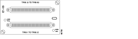
This module contains 63 E1 interfaces. The E1 traffic is mapped into VC-12 containers and multiplexed together according to the "5.1.1 Multiplexing Structure and Mapping Modes" section on page 5-1. Two high density LFH type connectors are used to interface the 63 E1's, 32 interfaces in the bottom connector and 31 interfaces in the top connector (one pair left unconnected). This module supports transparent data (G.703) and ISDN PRA.
Figure 14-1 High Density 63xE1 Module, E1-63
14.1.1 Power Consumption
21 W.
14.1.2 Connectors
The connector is a high density LFH connector
14.1.3 Compliance
14.2 Patch Panels
Two types of patch panels and a LFH cable are available for patching the 63 E1's interface on the High Density 63xE1 module.Please see the following sections for details.
Warning
This interface is considered SELV cicuit. Avoid connecting this interface to TNV circuits. The cables must not run with power cables, Network cables, or any other cables wich are not connected to SELV circuits. The electrical cables must not exit the building. If cables are connected to an equipment wich contains not SELV circuits, proper insulation between the ONS15305 E1 cables interface and the other equipment interfaces must be provided.
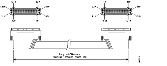
14.2.1 32XE1 LFH - LFH Cable
Figure 14-2 32XE1 LFH - LFH Cable
Available patch cable length : 3 M.
Cables with 10 M and 25 M length will be available soon.
Warning
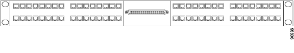
14.2.2 32xE1-LFH-RJ45 Panel
Figure 14-3 32xE1-LFH-RJ45 Panel
The RJ45 patch panel provide an interface with impedance 120 ohm.
14.2.2.1 Pinout
Table 14-2 RJ-45 Connector - Pinout
1
P120 OUT
2
N120 OUT
3
GND
4
P120 IN
5
N120 IN
6
SHIELD
7
NC
8
NC
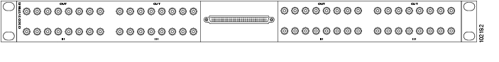
14.2.3 32xE1-LFH-1.0/2.3 Panel
This is a patch panel for the multi interface E1 connector. One connector can have up to 32 E1 interfaces.
The patch panel have 32 1.0/2.3 connectors for the E1 interfaces and one LFH connector for connection to the module. The patch panel includes baluns for all interfaces and convert the impedance from 75 ohm to 120 ohm. Cable with predefined length 3m, must be used to connect the patch panel to the multi interface E1 module. The patch panel can be mounted in 19" or ETSI racks and the height is 1U (44 mm).
Figure 14-4 32xE1-LFH-1.0/2.3 Panel
![]()
![]()
![]()
![]()
![]()
![]()
![]()
![]()
Posted: Fri Sep 14 09:46:59 PDT 2007
All contents are Copyright © 1992--2007 Cisco Systems, Inc. All rights reserved.
Important Notices and Privacy Statement.