Table Of Contents
Octal E1 Tributary Module, E1-8
13.1 Module Description
13.1.1 Power Consumption
13.2 External Interface
13.2.1 Connectors
13.2.2 Pinout
13.2.3 Compliance
Octal E1 Tributary Module, E1-8
13.1 Module Description
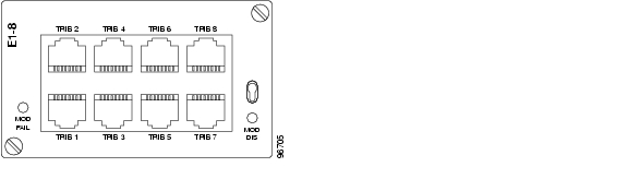
This module contains eight E1 interfaces. The E1 traffic is mapped into VC-12 containers and multiplexed together according to chapter 2.1.1 The physical interface use a RJ-45 connector and only supports120-ohm differential interface. The module does not contain any IP functionality. The interface supports both transparent data (G.703) and the NT functionality of ISDN PRA according to ETSI 300 233.
13.1.1 Power Consumption
3,5 W
13.2 External Interface
The interface is a 2Mbit/s E1 interface according to ITU-T G.703, 120ohm differential pair. Cabletype must be CAT5E-STP.
13.2.1 Connectors
The connector is a RJ-45 connector, with the following pin-out:
Table 13-1 E1 Interface Pinouts
Pin
|
Signal
|
1
|
P120 OUT
|
2
|
N120 OUT
|
3
|
GND
|
4
|
P120 IN
|
5
|
N120 IN
|
6
|
SHIELD
|
7
|
NC
|
8
|
NC
|
Figure 13-1 Octal E1 Tributary Module, E1-8
Note  Pin 6 is always AC connected to ground. The outer screen is always direct connected to ground.
13.2.2 Pinout
Table 13-2 Pinout-8xRJ45 2Mb
Signal name
|
Pin
|
I/O
|
Signal Description
|
PORT 1
|
|
|
|
RJ_TX1+
|
A1
|
O
|
Transmit+ Port1
|
RJ_TX1-
|
A2
|
O
|
Transmit- Port1
|
RJ_RX1+
|
A4
|
I
|
Receive+ Port1
|
RJ_RX1-
|
A5
|
I
|
Receive- Port1
|
PORT 2
|
|
|
|
RJ_TX2+
|
B1
|
O
|
Transmit+ Port 2
|
RJ_TX2-
|
B2
|
O
|
Transmit- Port 2
|
RJ_RX2+
|
B4
|
I
|
Receive+ Port 2
|
RJ_RX2-
|
B5
|
I
|
Receive- Port 2
|
PORT 3
|
|
|
|
RJ_TX3+
|
C1
|
O
|
Transmit+ Port 3
|
RJ_TX3-
|
C2
|
O
|
Transmit- Port3
|
RJ_RX3+
|
C4
|
I
|
Receive+ Port3
|
RJ_RX3-
|
C5
|
I
|
Receive- Port 3
|
PORT 4
|
|
|
|
RJ_TX4+
|
D1
|
O
|
Transmit+ Port 4
|
RJ_TX4-
|
D2
|
O
|
Transmit- Port 4
|
RJ_RX4+
|
D4
|
I
|
Receive+ Port4
|
RJ_RX4-
|
D5
|
I
|
Receive- Port 4
|
PORT5
|
|
|
|
RJ_TX5+
|
E1
|
O
|
Transmit+ Port 5
|
RJ_TX5-
|
E2
|
O
|
Transmit- Port5
|
RJ_RX5+
|
E4
|
I
|
Receive+ Port 5
|
RJ_RX5-
|
E5
|
I
|
Receive- Port 5
|
PORT 6
|
|
|
|
RJ_TX6+
|
F1
|
O
|
Transmit+ Port 6
|
RJ_TX6-
|
F2
|
O
|
Transmit- Port 6
|
RJ_RX6+
|
F4
|
I
|
Receive+ Port6
|
RJ_RX6-
|
F5
|
I
|
Receive- Port 6
|
PORT 7
|
|
|
|
RJ_TX7+
|
G1
|
O
|
Transmit+ Port 7
|
RJ_TX7-
|
G2
|
O
|
Transmit- Port7
|
RJ_RX7+
|
G4
|
I
|
Receive+ Port7
|
RJ_RX7-
|
G5
|
I
|
Receive- Port 7
|
PORT 8
|
|
|
|
RJ_TX8+
|
H1
|
O
|
Transmit+ Port 8
|
RJ_TX8-
|
H2
|
O
|
Transmit- Port8
|
RJ_RX8+
|
H4
|
I
|
Receive+ Port8
|
RJ_RX8-
|
H5
|
I
|
Receive- Port 8
|
13.2.3 Compliance
Table 13-3 E1 Interface Compliance
Standard
|
Comment
|
ETS 300 246
|
Connector
|
ETS 300 247
|
Connector
|
ETS 300 011
|
Impedance towards ground
Tolerable longitudinal voltage
|
ETS 300 126
|
Output signal balance
|
ITU-T G.703
|
Cable attenuation
Input reflection loss
Input port immunity against reflection
Output pulse mask
|
ITU-T G.783
|
Output jitter in the absence of input jitter
Output combined jitter
|
ITU-T G823
|
Max. tolerable input jitter
|