cc/td/doc/product/ong/15305/305docs
hometocprevnextglossaryfeedbacksearchhelp
PDF

Table Of Contents

Dual Optical LAN 1000Base-LX

10.1  Functional Description of Module

10.2  Power consumption

10.3  External Interface

10.4  Connector

10.5  Compliance

10.5.1  Jitter Optical Interface

10.6  References


Dual Optical LAN 1000Base-LX


10.1  Functional Description of Module

The GigE-2-LC module contains two Gigabit Ethernet (GE) interfaces that meet the 1000Base-LX specification in IEEE 802.3. This interface is a long haul interface based on single-mode fiber. The physical connector is an LC connector.

The module contains no TDM interfaces.

10.2  Power consumption

The power consumption of the GigE-2-LC module is 11 W.

10.3  External Interface

The interface offered is a Gigabit Ethernet (GE) interface that meets the 1000Base-LX specification in IEEE 802.3. This interface is a optical long haul interface based on single-mode fiber.

The optical LAN interface for 1000BASE-LX on the module uses a dual fiber interface LC style connector. With one fiber in each direction, it provides 1310nm wavelength and single mode fiber of type 10/125mm.

10.4  Connector

The physical connector is an LC connector, type LC SFF PTH.


Note The two RJ-45 connectors on the GigE-2-LC module must not be used.


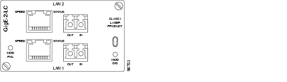
Figure 10-1 Dual Optical LAN 1000BASE-LX, GigE-2-LC

10.5  Compliance

Table 10-1 1000Base-LX Interface Compliance

Standard
Comment

IEEE 802.3

Clause 38, PDM sublayer and baseband medium

Clause 37, Auto negotiation

Clause 36, PCS and PMA sublayer

IEC 60825-1

Laser safety


10.5.1  Jitter Optical Interface

Table 10-2 gives the output jitter as specified in the data sheet for the optical transceiver.

Table 10-2 Output Jitter for Optical Transceiver

Transmit Signal Interface (from host to SFF-PTH-1250-LW-2X5)

Symbol

Parameter

Min.

Max.

Unit

Notes

DJ elec-xmit

PECL Deterministic Jitter (1.0625Gb/s)


0.12

UI

1

TJ elec-xmt

PECL Total Jitter


0.25

UI

1


Note Deterministic jitter (DJ) and total jitter (TJ) values are measured according to the methods defined in appendix A [1]. [1UI (Unit Interval) = 800ps at 1.25Gb/s, and 1 UI = 941ps at 1.0625Gb/s]. Listed values apply to 1.0625Gb/s, 1.25Gb/s transceivers accept TJ < 0.24 UI.


Table 10-3 gives the input jitter as specified in the data sheet for the optical transceiver.

Table 10-3 Input Jitter for Optical Transceiver

Receive Signal Interface (from SFF-PTH-1250-LW-2X5 to host)

Symbol

Parameter

Min.

Max.

Unit

Notes

DJ elec-rcv

PECL Deterministic Jitter (1.0625Gb/s)


0.36

UI

1

TJ elec-rcv

PECL Total Jitter


0.61

UI

1


Note Deterministic jitter (DJ) and total jitter (TJ) values are measured according to the methods defined in appendix A [1]. Jitter values assume worst case input jitter. [1UI (Unit Interval) = 800ps at 1.25Gb/s, and 1UI = 941ps at 1.0625Gb/s]. Listed values apply to 1.0625Gb/s, 1.25Gb/s transceivers have TJ < 0.749 UI.


10.6  References

IEC/IEEE

IEC 60825-1: Laser safety.

IEEE 802.3, 1998 Edition: Part 3: Carrier sense multiple access with collision detection (CSMA/CD) access method and physical layer specifications.

IEEE 802.3z: GE Network Standard.

ANSI

American National Standards Institute Inc. (ANSI), T11.2/Project 1230/Rev10, Fibre Channel-Methodologies for Jitter Specifications (MJS) Drafts of this standard are available to members of the standards working committee. For further information see the T11.2 web site at www.t11.org.

ANSI/EIA/TIA-455-127-1991 [B8].

ANSI/EIA-455-95-1986 [B7].

ANSI/TIA/EIA-526-4A-1997 [B13].

ANSI X3.230-1994 [B19] (FC-PH), Annex A, A.5, Relative intensity noise (RIN) measuring procedure.

ANSI X3.230-1994 [B19] (FC-PH), Annex A, A.4.2, Active output interface eye opening measurement.

ANSI X3.230-1994 [B19] (FC-PH), Annex A, A.4.3,DJ Measurement.

ANSI/EIA/TIA-526-14A [B14].


hometocprevnextglossaryfeedbacksearchhelp

Posted: Fri Sep 14 11:02:33 PDT 2007
All contents are Copyright © 1992--2007 Cisco Systems, Inc. All rights reserved.
Important Notices and Privacy Statement.