|
|

Table Of Contents
2.2.1 SDH Multiplexing and Mapping
2.3 Switch Features (Bridging)
2.4.4 Supervision by the Exchange Termination (ET)
2.4.5 ET generated Downlink Sa6 Codes
2.4.6 NTE generated Uplink Sa6 Codes
2.4.7 Handling of CRC-4 Errors
2.9 Automatic System Clock Setting
2.10.1 Back to Back Application
2.10.2 Remote Back to Back Application
2.10.3 Headquarter Office to Branch Office
2.11.1 Various ONSCLI Management Access Solutions
2.11.2 Command Line Interface (ONSCLI)
2.11.3 Management Connectivity
2.13 DCN Configurations Supported
2.13.2 DCN on customer Ethernet Port or WAN Port
2.13.3 Broadcasting over Management Port and HDLC- DCC
2.13.4 Routing between Management Port and IP/PPP DCC-R
Backup and Restoration of Configuration Data
Software Download (Remote Access)
2.18 Software Download (Local Access)
Product Overview
This section describes the functionality and the features of the ONS 15302.
2.1 Functional Overview
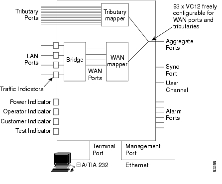
The Cisco ONS 15302 is an integrated access device for use in fiber optic networks. The ONS 15302 combines Ethernet- and TDM-traffic inside an SDH STM-1 frame structure that can be easily carried across the network. The bandwidth of the Ethernet channel is configurable up to 100 MBits/s (Mbps) true wire-speed. The Ethernet part of the Cisco ONS 15302 consists of a bridge, ( Figure 2-1).
Each tributary interface is mapped into a VC-12 container while the WAN traffic is mapped into a configurable number of VC-12 containers. Because the latter mapping is proprietary, the Ethernet-WAN traffic generation and termination must be realized in a Cisco device in both ends of a connection.
The ONS 15302 management solution is based on an embedded SNMP agent. A graphical user interface (GUI) based element manager application can be used as a craft terminal and for remote supervision of ONS 15302 devices. The ONS 15302 also provides a simple VT100 command line interface (ONSCLI) for direct communication with the embedded SNMP agent.
The ONS 15302 STM-1 port is fully compatible in existing SDH Transport Networks.
Figure 2-1 ONS 15302 Functional Overview
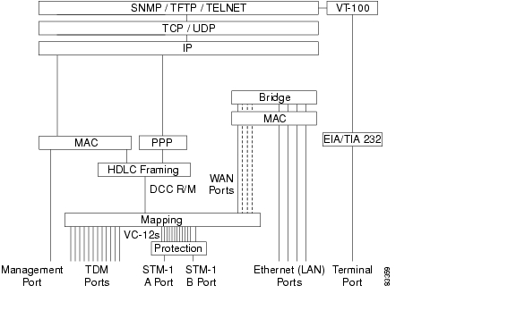
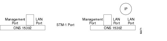
From an element management perspective, the ONS 15302 is a multi-protocol machine with several types of interfaces as shown in Figure 2-2.
Figure 2-2 Functional Model for the ONS 15302
2.2 Features
2.2.1 SDH Multiplexing and Mapping
The aggregate interface supports only terminal multiplexer functions, and 63xVC-12 mapping.
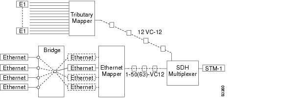
Figure 2-3 shows the internal structure of ONS 15302. The bridge receives an Ethernet frame/IP datagram on one of the ports and decides on which port to send it out. The Ethernet Mapper converts between Ethernet frames and VC-12s while the Tributary Mapper converts between E1 signals and VC-12s. The SDH Multiplexer is responsible for the multiplexing of VC-12s into STM-1. The VC-12s are sent to and received from either the Tributary Mapper or the Ethernet Mapper.
Figure 2-3 Multiplexing and Mapping in the ONS 15302
The WAN traffic is mapped into a number of VC-12 containers in a round robin fashion with an inverse multiplexer function. The Ethernet traffic is mapped into one or a number of VC-12 containers.
It is possible to have one to four WAN channels in the ONS 15302. The total bandwidth for one WAN channel can not be greater than 100 Mbit/s (Mbps) or 50xVC-12 containers.Up to 63xVC-12 containers may be used for WAN traffic if more than one WAN channel is used.
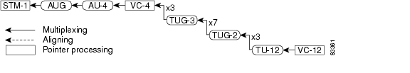
The ONS 15302 can utilize all 63xVC-12, it is just a matter of hardware. When a WAN module is inserted you have 4xWAN ports, which can freely be configured 50xVC-12 container, though still limited to a total amount of 63. If any E1 interfaces are needed this will of course affect available containers for Ethernet ( Figure 2-4).
Figure 2-4 Multiplexing Structure in STM-1
The mapping between the tributary interfaces and the WAN port is fully flexible. An example of mapping is shown in Table 2-1.
The VC-12 containers can be freely allocated to the different WAN ports or the tributary ports.
2.2.2 Protection
The ONS 15302 offers 1+1 linear Multiplex Section Protection (MSP). The protocol used for K1 and K2 (b1-b5) is defined in ITU-T G.841, clause 7.1.4.5.1. The protocol used is 1+1 bi-directional switching compatible with 1:n bi-directional switching.
The operation of the protection switch is configurable as described in Table 2-2.
2.2.3 Performance Monitoring
The ONS 15302 offers full G.826 performance monitoring at the RS, MS, VC-4, and VC-12 levels in the SDH hierarchy. This includes B1 near end in RSOH section, B2 near and far end in MSOH section, B3 near and far end at VC-4 level and BIP-2 near and far end at VC-12 level.
The ONS 15302 calculates excessive error and degrade signal defects assuming Poisson distribution of errors, according to ITU-T G.826.
The excessive error defect (dEXC) is detected if the equivalent BER exceeds a preset threshold of 10 exp -5, and be cleared if the equivalent BER is better than 10 exp -6, according to ITU-T G.806.
The degraded signal defect (dDEG) is detected if the equivalent BER exceeds a preset threshold of 10 exp -X, where x=6,7,8 or 9. The dDEG is cleared if the equivalent BER is better than 10 exp -(X+1), according to ITU-T G.806.The threshold is individually configurable for the different levels in the SDH hierarchy, from 10 exp -6 to 10 exp -9.
2.2.4 Synchronization
ONS 15302 can synchronize to the following sources:
•
An STM-1 interface (working link or backup link)
•
•
•
Tributary synchronization is only relevant when in PRA mode at the chosen tributary.
The synchronization source is a configurable parameter. If it is impossible to synchronize to the selected source, an alarm will be raised, and the system will automatically switch to free running, that means the local oscillator.
Switchback to the selected source is performed automatically whenever it becomes possible again. The alarm is cleared when the switchback is successful.
The ONS 15302 operates in three different modes:
•
•
•
The default synchronization source is the local oscillator. The tolerance for this oscillator is +/- 10 ppm. ONS 15302 also provides a 2048 kHz sync output for synchronization of external equipment.
Note
Note
2.3 Switch Features (Bridging)
The bridge is a transparent multi port remote Ethernet bridge as specified in IEEE 802.3. The Bridge consists of four LAN ports and four WAN port. Each port may have its own MAC address, but in most configurations one MAC address for the whole bridge is sufficient. The four LAN ports support 10/100BaseT Ethernet for UTP cables. Both 10 Mbit/s (Mbps) and 100 Mbit/s (Mbps) are supported with auto negotiation. The LAN ports are compatible with IEEE 802.3.
The bridge supports the following features:
•
•
•
•
•
•
•
•
•
•
•
•
•
•
•
•
•
2.4 TDM Features
2.4.1 Tributary Ports
ONS 15302 provides 12 120 ohm 2.048 MHz Tributary Ports on the customer side. 75 ohm operation is supported by adding an external balun.
Each Tributary Port can be individually configured to run in one of the following modes:
•
•
Note
2.4.1.1 Transparent Transmission Mode.
In this mode 2.048 Mbit/s plesiochronous data and timing are transferred independently of frame structure. The two directions of transmission are completely independent of each other.
Downstream AIS is generated on loss of signal or loss of optical frame alignment.
2.4.1.2 ISDN Primary Rate Access (PRA) Transmission Mode.
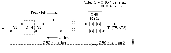
The functional layout compliant to pr. ETS 300 233 is shown in below.
Figure 2-5 ONS 15302 ISDN PRA Configuration
2.4.2 Downlink Transfer
The LTE is transparent to the 2 Mbit/s (Mbps) signal. However, monitoring the G.704 multiframe format is performed for detection of loop back 1 command from the Exchange Termination (TS 0 bit Sa6).
The NTE terminates CRC-4 section 1 by the Receiver (R) circuits, which pass the signal to the Generator (G) circuits with indication of basic frame start. The G circuits generate new TS 0 basic frame and multiframe to CRC-4 section 2, and pass transparently TS1 - TS31 and from TS 0 the RAI bit and the Sa-bits 4 to 8. AIS is generated to the TE on loss of signal and when R circuits have lost alignment to G.704 basic frames.
2.4.3 Uplink
The NTE terminates CRC-4 section 2 in the R circuits, which pass the signal to the G circuits with indication of basic frame start. The G circuits generate new TS 0 basic frame and multiframe to CRC-4 section 1 and pass transparently TS1- TS31 and from TS 0 the RAI bit and the Sa-bits 4,7 and 8.
The G circuits generate substituted frames to the ET on loss of signal or loss of alignment to basic G.704 frames from TE.
The LTE is transparent to the 2 Mbit/s (Mbps) signal.
On loss of optical line signal, the LTE generates an auxiliary pattern AUXP=1010.. to the ET.
2.4.4 Supervision by the Exchange Termination (ET)
The TS 0 bits Sa5 and Sa6 are used for supervision. Bit Sa5 being 0 downlink and 1 uplink, indicates the direction of transmission.
2.4.5 ET generated Downlink Sa6 Codes
Normal condition Sa6 = 0000
Loop back 1 command to LTE Sa6 = 1111
Loop back 2 command to NTE Sa6 = 1010
2.4.6 NTE generated Uplink Sa6 Codes
2.4.7 Handling of CRC-4 Errors
CRC-4 errors detected in R circuits downlink and uplink are inserted as E bits to the ET and TE respectively.
If multiframe alignment is not obtained, the NTE reports all E bits 0 error.
Detected bit errors related to CRC-4 section 2 are reported to the ET by use of the two last bits of the Sa6 code in normal operational condition.
Table 2-4 CRC-4 Section 2 Bit
a)
CRC-4 errors detected by the NTE:
0010
b)
CRC-4 errors reported as E-bits from the TE:
0001
a) + b) or no MF alignment to signal received from the TE:
0011
ITU-T Rec.G.706, ANNEX B is applied to CRC-4 section 2 which means that the NTE stops searching for MF alignment after a given period of time without further actions. Continuous Sa6 = 0011 indicates to the ET that quality information is not available from CRC-4 section 2.
2.5 Test Loops
Two test loops are provided per Tributary Port, one in the customer direction (LL3) and one in the network direction (LL2), ( Figure 2-6). One Tributary Port can have only one loop activated at a time. The test loops can be activated, deactivated and monitored by the management system. The loop control logic depends on the tributary mode (TRA or PRA).
•
•
It is possible to change the tributary mode regardless of the state of the loops. If the mode is changed, the loops will be cleared. The Test LED is on if any tributary loop is activated, regardless of the tributary mode.
To change the tributary mode, the loop must be cleared.
The Test Indicator LED is on if any tributary loop is closed, regardless of the tributary mode. This release does not support any monitor points.
Figure 2-6 Test Loops Schematic View
2.6 Alarm Ports
The ONS 15302 provides facilities to report four auxiliary alarm inputs for associated equipment, for example power unit failure, battery condition, cabinet door etc. These alarms are activated by an external loop between a pair of contacts.
The polarity of the auxiliary alarm input ports is a configurable parameter, this means alarm can be defined either as a loop closed or a loop open condition.
The alarms are reported to the management system. Each alarm input port may have an individual configurable textual description associated with it.
The ONS 15302 provides also support for two alarm output ports (Alarm out 1 and Alarm out 2) used to signal equipment alarms and traffic related alarms. Alarm out 1 and Alarm out 2 reflect the status of the operator LED and the customer LED respectively.
2.7 LED Indicators
The LED indicators are used to visualise the ONS 15302 status:
2.8 User Channel
A transparent user channel is provided (F1 byte in RSOH) for transportation of general data. The interface is balanced RS485 and supports synchronous 64 kbit/s or asynchronous 19.2 kbit/s by configuration.
2.9 Automatic System Clock Setting
The ONS 15302 supports time protocol (RFC 868) for automatic date and time adjustment. To utilize this feature a TP server must be available in the network.
Because the time protocol provides UTC (GMT) only, and does not take into account the Day Light Saving Time (summer time), an additional parameter (UTC Delta) allows the user to get the local time. This parameter must be adjusted twice a year to take into account the Day Light Saving Time.
2.10 Applications
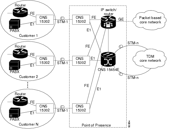
2.10.1 Back to Back Application
Normally the ONS 15302 at the customer site is connected to an ONS 15302 at the operator point of presence (PoP). A number of these systems can be connected in a star network and the Ethernet traffic is groomed by an Ethernet switch before it is transmitted to the core network. Figure 2-7 shows the layout of a typical system with the ONS 15302 incorporated. The network in this figure does not have a separate Ethernet backbone network, but this could easily be supported.
Figure 2-7 Back to Back Configuration across the Access Loop
2.10.2 Remote Back to Back Application
The ONS 15302 can also be directly connected to the SDH transport network if the operator wants to do Ethernet grooming at a different site as shown in the figure below.
Figure 2-8 Typical System with no Local Grooming in the PoP
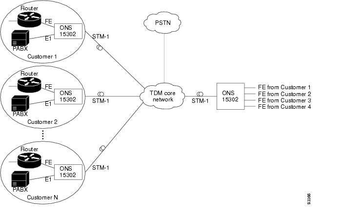
2.10.3 Headquarter Office to Branch Office
The ONS 15302 can be connected to four different ONS 15302 units without any additional Ethernet switch Figure 2-9.
Figure 2-9 Typical System when connected to an ONS 15302
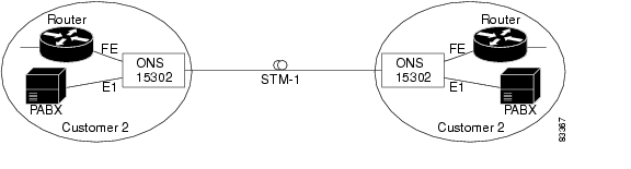
2.10.4 Campus Application
The ONS 15302 can also be connected back to back without any connection to external networks Figure 2-10.
Figure 2-10 Typical Network when used in a Campus Application
2.11 Management
The following main features are supported by the ONS 15302 management system:
•
•
•
•
•
•
•
The ONS 15302 management solution is based on an embedded SNMP agent, which can be accessed locally or from a remote management application.
Supported MIBs
The following standard Management Information Base are supported.
2.11.1 Various ONSCLI Management Access Solutions
ONS 15302 is managed by means of the Optical Network System Command Line Interface (ONSCLI). ONSCLI is an ASCII based VT100 terminal interface. The ONS 15302 can be fully managed by means of the ONSCLI interface.
Figure 2-11 Local Management with ONSCLI
Figure 2-12 Possible Remote Management via In Band Traffic
(Looping remote LAN Port to Management Port. See Inband via one of the LAN Ports for restrictions).
Note
2.11.2 Command Line Interface (ONSCLI)
ONS 15302 supports a serial EIA/TIA 232 interface called ONSCLI. ONSCLI is a line oriented ASCII based management interface, which provides a simple local connection to any VT100 compatible terminal. ONSCLI is protected by a password.
The ONS 15302 also supports the connection of a remote ONSCLI terminal over Telnet/IP.
2.11.3 Management Connectivity
A local Ethernet interface, called the Management Port, is available for connecting to a management DCN. This port is compatible with IEEE 802.3 and supports 10/100BaseT Ethernet for UTP cables.
If an ONS 15302 has no connectivity to the management DCN via the Management Port, mechanisms for transporting management information in the STM-1 DCC channel are provided.
The ONS 15302 management system is based on SNMP and an IP based DCN. However, if an IP based DCN is not available, ONS 15302 provides a mechanism for connecting via IpPPP based DCN.
2.11.3.1 Ways of Connecting to the Management DCN
ONS 15302 can connect to the management DCN in different ways:
Via the dedicated Ethernet Connector (Management Port)
This solution assumes that both ONS 15302s in a pair have local IP- or OSI connectivity.
Via a proprietary HDLC based Protocol in the STM-1 DCC (DCC-R or DCC-M)
This solution assumes that one of the two ONS 15302s in a pair has IP connectivity via the Management Port and that the DCC channel is transparent between the two devices. In this mode, packets received via the Management Port are broadcasted over the DCC HDLC if the MAC address is within the range assigned to Cisco.
Inband via one of the LAN Ports
In this case the Management Port must be physically connected to one of the LAN ports via an external HUB. The management traffic is carried over the Bridge WAN port. If the ONS 15302 device is not managed by the customer itself, the LAN port used for management must belong to a separate VLAN, this means only three ports are left for customer access.
IP Inband
IP inband means that LAN and WAN ports are carrying management traffic together with customer traffic. The configuration is described in DCN Configurations Supported.
When using IP inband, the management traffic can be routed or switched (using VLANs). If routed, the routing is carried out in hardware (FFT) if IP routing is enabled. Otherwise, IP forwarding is used, this means software based.
Every ONS 15302 has one and only one IP address allocated to it. ONS 15302 also keeps the IP address of its mate ONS 15302. This simplifies the toggling between two ONS 15302s in a pair. In addition, the flexibility above implies the actual DCN strategy must be decided and configured per device (parameters like DCC enable/disable, IP/HDLC etc.).
All ONS 15302 protocol stack options for implementing the above DCN strategies is illustrated in Figure 2-2.
2.12 DCN Features
The required DCN protocol support is shown in Figure 2-2.
The ONSCLI apply the standards in Table 2-7.
2.12.1 SDH DCC Channels
Both DCCR (Regenerator Section) and DCCM (Multiplexer Section) channels are supported independently. Note that both channels should not be active on the same port simultaneously, as this will result in looping of the traffic. Activation/deactivation of DCC channels is configurable on a per port basis.The SDH DCC IP/PPP transport mechanism supports only traffic on the DCC-R. The DCC-M is by default turned off, when the IP/PPP/DCC-R mode is enabled.
TELNET
Telnet sessions are possible via all paths of management traffic. Multiple Telnet sessions are not possible.
Security
It is possible to restrict management access to the ONS 15302.
2.13 DCN Configurations Supported
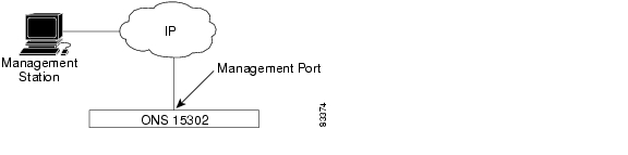
2.13.1 DCN on Management Port
This configuration is applicable for users connecting an IP based DCN directly to the ONS 15302. For this type of connection, the management port is used.
Figure 2-13 DCN on Management Port
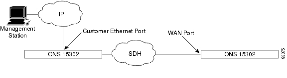
2.13.2 DCN on customer Ethernet Port or WAN Port
This configuration is applicable if the user is connected to one of the customer Ethernet ports, or one of the WAN ports (in band management).
Figure 2-14 DCN on Customer Ethernet Port or WAN Port
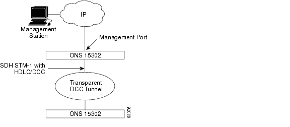
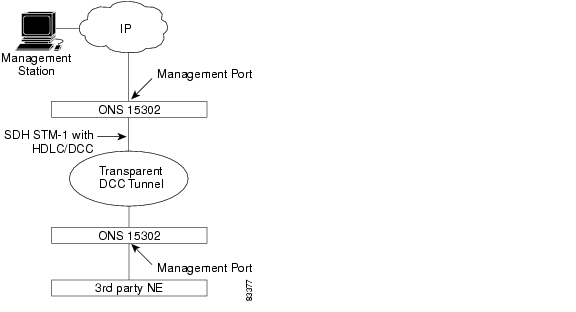
2.13.3 Broadcasting over Management Port and HDLC- DCC
This configuration is applicable for a user having a subnet of Cisco devices and an IP based DCN connected to the management port of the ONS 15302.
Figure 2-15 Broadcasting over Management Port and HDLC- DCC
In order not to saturate the DCC with unnecessary traffic, a filtering mechanism for MAC frames can be enabled. If the filter is enabled, MAC frames received via the management port are broadcasted over DCC only if their destination MAC address is within the range assigned to a Cisco system. If the filter is disabled, all MAC frames (regardless their destination MAC address) received via the management port are broadcasted over DCC.
An ONS 15302 configured to broadcast management traffic over the management port and DCC (as described above) can be used to provide IP DCN connectivity to a 3rd party network element via its Management Port, provided than the filter mechanism for MAC frames is disabled. A typical configuration is described below.
To prevent indefinitely packet looping and/or packet proliferation, the following restrictions apply to the broadcast solution presented below
•
•
Figure 2-16 IP DCN connectivity to a 3rd Party Network Element
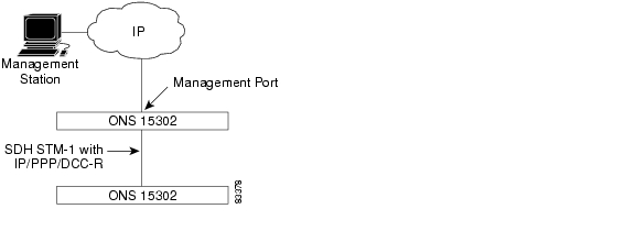
2.13.4 Routing between Management Port and IP/PPP DCC-R
This configuration is applicable for a user having a subnet of Cisco devices and an IP based DCN connected to the management port of the ONS 15302. This configuration allows PPP encapsulated IP management traffic to be transported over the DCC-R channel.
Figure 2-17 IP DCN connectivity to a 3rd Party Network Element
2.14 ONS 15302 Management
The description of the ONS 15302 management system refers to manageable objects as listed in Table 2-8.
2.15 Fault Management
2.15.1 Alarm Handling
The alarms are related to a managed object as defined in Table 2-8.
The ONS 15302 keeps a record of current and historical alarm events.
The list of current alarms contains the following parameters for each alarm:
•
•
•
•
•
•
Port alarms are suppressed if the port itself is disabled. In order to avoid alarm flooding, alarms at different levels are correlated. Lower order alarms are suppressed if a more important alarm at a higher level is active.
In addition to the alarms, the ONS 15302 may generate a number of events. The events are not stored in the current alarm list, but they are appended to the historical alarm list in the same way as the alarms. The historical alarm list contains the same parameters per alarm as the current alarm list, and in addition the following parameter:
•
Both the alarms and the events generate SNMP traps. The traps can be sent to a number of management stations. It is possible to turn SNMP trap sending on or off on a per manager basis. This is the only alarm filtering mechanism provided by the ONS 15302.
Note
Note
Note
Table 2-9 Criterions for Turning Alarms On and Off
MSDEG
> 10 exp -7
< 10 exp -8
LPDEG
> 10 exp -6
< 10 exp -7
2.15.2 Alarm Severity
The Alarm Severity is configurable per alarm object. Default values are assigned automatically as shown in Table 2-11.
2.15.2.1 Alarm Definition
The list below contains all the alarms that are defined for the ONS 15302. For some of the Alarm IDs, the direction (RX or TX) is an integral part of the name. This terminology is used for the direction:
•
•
2.15.3 Alarm Definitions
The different alarms together with their relations to the managed objectsare defined in "Managed Object,"
2.15.4 Alarm Parameters
Table 2-11 defines the parameters associated with an alarm.
.
The Alarm Severity is configurable per alarm object. Default values are assigned automatically.
2.15.5 Alarm Suppression
Alarms are suppressed if the object subject to alarm is disabled. It is possible to inhibit alarm reporting for a specific managed object. It is possible to inhibit all alarms from one ONS 15302. All SDH and PDH objects have two configurable persistency filters:
•
•
In addition, the STM-1 interfaces follow the alarm suppression, ( Table 2-12).
2.15.5.1 Alarm Suppression for Tributary Tx-Alarms
Table 2-13 Alarm Suppression for Tributary Tx-Alarms
Tributary
LOSTX
yes
LFATX
LFATX
yes
2.15.5.2 VC-4 Alarm Suppression for EXC/DEG
Table 2-14 VC-4 Alarm Suppression for EXC/DEG
VC-4
EXC
yes
DEG
no
2.15.5.3 RS Alarm Suppression for EXC/DEG
Table 2-15 RS Alarm Suppression for EXC/DEG
RS
EXC
yes
DEG
no
2.15.5.4 MS Alarm Suppression for EXC/DEG
Table 2-16 MS Alarm Suppression for EXC/DEG
MS
EXC
yes
DEG
no
2.15.5.5 VC-12 Alarm Suppression for EXC/DEG
Table 2-17 VC-12 Alarm Suppression for EXC/DEG
VC-12
EXC
yes
DEG
no
2.15.6 Alarm Collection
It is possible to view the alarms of all ONS 15302 devices present in the network, for example currently reachable from the management system. The ONS 15302 device stores a list of all current alarms and a log of alarm events. The size of the log of alarm events is 1000 entries.
2.15.7 Alarm Classification
It is possible for the operator to change the assignment of alarm severity for each pair of Object Type Alarm ID.
The possible severity levels are:
•
•
•
•
2.15.8 Alarm Indication
The Customer LED on indicates that one or more Tributary alarms are on.
The Operator LED on indicates any alarm on, other than AUX alarms and Tributary alarms.
It is possible to define an alarm severity threshold for each LED defining which alarm severity shall turn on the corresponding LED.
2.16 Configuration Management
Backup and Restoration of Configuration Data
It is possible to back up the configuration data of an ONS 15302 device. It is possible to reload the configuration from the back up. The back up media must be a central repository.
Note
Software Download (Remote Access)
It is possible to download a new software version to the ONS 15302 device. The download process does not influence traffic processing. The new software is used when booting after the next restart. The rebooting is always traffic affecting on IP traffic, but only traffic affecting on TDM traffic if the new software is changes in FPGAs.
Device Reset
It is possible to reset (reboot) the device with or without resetting the current configuration. Reboot does not affect the TDM traffic.
Managed Object Attributes
All attributes defined in the chapter "Managed Object," are available for read or read/write access by the management applications specified in "Various ONSCLI Management Access Solutions" section.
2.17 Performance Monitoring
The performance monitoring functions specified in Table 2-18 is available in ONSCLI.
2.17.1 Aggregate Port
Table 2-18 defines the mapping between the dialogue parameters and MIB variables for the Aggregate Port Statistics submenu.
2.17.2 Bridge Port
Performance counters for the Bridge ports (including the WAN port) are available for the manager via the following variables in the RMON MIB:
•
•
•
•
•
•
•
•
•
•
•
•
•
•
•
•
•
As opposed to the Aggregate port counters, the Bridge port counters must be started and stopped by the operator.
ONS 15302 keeps no history records for the Bridge port counters.
2.18 Software Download (Local Access)
It is possible to load a new software version by means of a PC directly attached to the ONSCLI Port. This service requires local operator presence at the ONS 15302, ( "Troubleshooting").
The file is loaded by means of the X modem protocol, and the transfer rate is 15.200 kbit/s.
Note
2.19 Security
The management access to the ONS 15302 is controlled by parameters in a community table. This table can only be modified by users with Super access rights. The parameters in the community table are only visible for Super users.
For each defined user, the following parameters must be provided:
•
•
•
•
One management station (IP address) may have several users with different access rights. These users are identified by means of the community string.
The ONSCLI access is controlled by means of a password, one for the local access and one for the Telnet access. A management station Super user can modify the ONSCLI password.
The ONSCLI user has Super access rights.
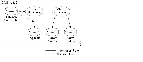
2.20 Management Logs
This subsection summarizes the various logs used for alarms, errors and statistics. As visualized in figure the figure Management logs.
In addition to the logs described below, the system provides logs for troubleshooting, containing detailed debug information. These logs are not available for normal users, and they are not specified in this document.
Figure 2-18 Management Logs
![]()
![]()
![]()
![]()
![]()
![]()
![]()
![]()
Posted: Tue Jan 8 08:20:36 PST 2008
All contents are Copyright © 1992--2008 Cisco Systems, Inc. All rights reserved.
Important Notices and Privacy Statement.