|
|

Table Of Contents
Provisioning with ASH and SNMP
4.1 Log In via RS-232 (EIA/TIA-232) Port Using HyperTerminal
4.3 Log In via LAN Port Using Telnet (Optional)
4.5 Set Power Bus Mode (Simplex or Duplex)
4.6 Verify Amplifier Operational Status
4.13 Back Up System Configuration
4.14 Restore System Configuration
Provisioning with ASH and SNMP
This chapter discusses the provisioning procedures for the Cisco ONS 15216 EDFA2 using SNMP and a proprietary command line interface named the ASH shell. See "Provisioning with TL1" for provisioning information using TL1 commands in the TL1 shell.
The provisioning procedure for the ONS 15216 EDFA2 in the ASH shell is as follows:
1.
Log In via RS-232 (EIA/TIA-232) Port Using HyperTerminal
3.
5.
6.
7.
9.
10.
11.
12.
13.
14.
The following sections describe these steps in detail.
4.1 Log In via RS-232 (EIA/TIA-232) Port Using HyperTerminal
You must log in through the RS-232 (EIA/TIA-232) port and set the ONS 15216 EDFA2 IP address before access can be available via the LAN port. (See the "Log In via LAN Port Using Telnet (Optional)" section.)
Step 1
Step 2
Step 3
By default the ONS 15216 EDFA2 is in TL1 shell, so this step may be required to proceed in ASH shell. When in TL1 shell, the screen opens to a simple prompt (>). To change to ASH shell, log in using the procedure in the "Log In via RS-232 (EIA/TIA-232) Port Using HyperTerminal" section, and then enter the following command at the sid/tid name prompt:
sidtidname:ONS15216 EDFA2> ED-NE-GEN:::123:::CLI=ASH;Then enter the following command at the hostname prompt:
sidtidname:ONS15216 EDFA2> INIT-SYS::ALL:1234::1;The ONS 15216 EDFA2 should log you off and then bring up the ASH shell login window.
Step 4
Example 4-1 ASH Shell Login Window
-- LOGIN ------------------------------------------------------------Username: { }Password: { }[Login]Step 5
The default user name and password is CISCO15 with no password (press Enter).
Note
Step 6
Example 4-2 ASH Shell Login Response
Welcome to ONS15216 EDFA2 Console (v2.4.0)************************** Warning *********************************This system is restricted to authorized users for business purposes.Unauthorized access is a violation of the law. This service may bemonitored for administrative and security reasons.By proceeding you consent to this monitoring.********************************************************************ash:hostname:ONS15216 EDFA2>An EIA/TIA-232 link to the ONS 15216 EDFA2 is established. The user can now provision the ONS 15216 EDFA2.
4.2 Set IP Address
Before connecting the ONS 15216 EDFA2 to a LAN, it is mandatory to set the ONS 15216 EDFA2 IP address through a local serial communication interface using the RS-232 (EIA/TIA-232) port on the front of the module.
Step 1
Step 2
Example 4-3 Setting IP Address, Subnet Mask, Gateway Address, and Host Name
ash:hostname:ONS15216 EDFA2> snmp row set local cerent15216EdfaSromIpMgmtGroupcerent15216EdfaSromIpMgmtEnetAddress 0.0.0.0cerent15216EdfaSromIpMgmtEnetSubNetMask 0.0.0.0cerent15216EdfaSromIpMgmtDefaultRouterAddress 0.0.0.0cerent15216EdfaSromIpMgmtHostName ""Because row set is being used in this command, the user is prompted row by row to enter the IP address, the subnet mask, the gateway address, and the host name (community ID).
Step 3
Step 4
4.3 Log In via LAN Port Using Telnet (Optional)
Provisioning of the ONS 15216 EDFA2 can be accomplished entirely through the RS-232 (EIA/TIA-232) port using CLI commands. After an IP address is assigned, it may be easier to provision the ONS 15216 EDFA2 using Telnet or an SNMP manager. A Telnet client is needed for CLI commands over IP. A generic SNMP manager is required for SNMP management over IP. After connecting the ONS 15216 EDFA2 to the network through its RJ-45 LAN port (see "LAN Interface (Ethernet)" section), the user can configure the module to accept SNMP and CLI commands via Telnet using the following procedure:
Step 1
Step 2
Step 3
telnet <ONS 15216 EDFA2 IP address> 8023Specifying port 8023 ensures login through the ASH shell. If no port is specified, the ONS 15216 EDFA2 responds in the shell that the ONS 15216 EDFA2 is set to. (TL1 is the default shell.)
Step 4
You are now connected to the ONS 15216 EDFA2 via Telnet.
4.4 Set Date and Time
Use the snmp attribute set local cerent15216EdfaRtcDateAndTimeLocalString command to set the date, time, and time zone. Entries must follow this format: "yyyy-m-d,h:m:s.s +h:m". Following the space, the time zone is set as +/- hours from Greenwich Mean Time (GMT) (also designated as universal coordinated time (UTC)) followed by a colon and minutes ahead for daylight savings. For example, Pacific Daylight Time would be -8:60 and Greenwich Mean Time would be +0:0. See Example 4-4.
Example 4-4 Setting the Date and Time
ash:hostname:ONS15216 EDFA2> snmp attribute set local cerent15216EdfaRtcDateAndTimeLocalString
"2002-6-30,14:8:30.0 -8:60"
4.5 Set Power Bus Mode (Simplex or Duplex)
The ONS 15216 EDFA2 allows users to set a simplex (one power source-Bus A) or duplex (redundant power source-Bus A and Bus B) Power Bus mode. Use the snmp attribute set local cerent15216EdfaPowerBusMode command to set the desired Power Bus mode. The default mode is duplex. See Example 4-5.
Example 4-5 Setting the Power Bus Mode
ash:hostname:ONS15216 EDFA2> snmp attribute set local cerent15216EdfaPowerBusMode simplex4.6 Verify Amplifier Operational Status
To ensure that the amplifier is working correctly on the optical level, you must verify the amplifier operational status. Use the snmp table display local cerent15216EdfaOverallStatusGroup command to verify amplifier operational status. Example 4-6 displays the output of this command.
Example 4-6 Verifying the Amplifier Operations Status
ash:hostname:ONS15216 EDFA2> snmp table display local cerent15216EdfaOverallStatusGroupCLASS CERENT-15216-EDFA-MIB.cerent15216EdfaOverallStatusGroup ::={cerent15216EdfaInPoweruW = 279;cerent15216EdfaInPowerdBm = -1555;cerent15216EdfaOutPowermW = 476;cerent15216EdfaOutPowerdBm = 678;cerent15216EdfaConstGainOverallGainMeasured = 219;cerent15216EdfaVariableGainPreAttenuationMeasured = 10;};The input power (signal) should be consistent with the input power measured during the optical connection procedure. See the "Optical Connection Procedure" section for more information. The output power value should be 22 dB greater than the input, assuming that the default gain setting is 22 dB.
Note
4.7 Set Gain
To ensure that the ONS 15216 EDFA2 output signal is received by the transceiver in the network element, it is important that the gain is set correctly.
The desired output power per channel is dependent on the number of channels traversed in the amplifier. The user sets the gain of the amplifier depending on the input power (signal) level, the network application, and the required receiver specifications necessary for error-free operation. Gain range is provided in Table 3-1.
To set the amplifier gain, enter the snmp attribute set local cerent15216EdfaConstGainOverallGain gainvalue command, where gainvalue is the desired gain multiplied by ten. For example, if the desired gain is 20 dB, the gainvalue would be set to 200. Example 4-7 shows the command used to set the gain.
Example 4-7 Setting the Gain
ash:hostname:ONS15216 EDFA2> snmp attribute set local cerent15216EdfaConstGainOverallGain
200
Note
4.8 Set Alarm Thresholds
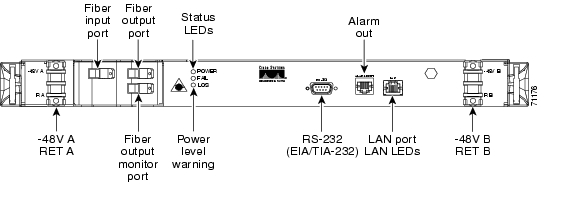
Alarm thresholds are set so that the network operator can be notified when valid alarms occur via the RJ-45 ALARM OUT and RJ-45 LAN ports on the front panel of the ONS 15216 EDFA2. (See Figure 4-1.)
Figure 4-1 ONS 15216 EDFA2 Front Panel
Alarms are reported for the following conditions:
•
•
•
Alarms can be connected to a network operations center (NOC) network management system (NMS) via a network element miscellaneous discrete input and/or office alarm panel/system.
For a full description of alarm threshold command attributes, refer to "SNMP MIB Configuration" or Chapter 6, "ASH Commands."
To display the alarm thresholds, use the snmp table display local cerent15216EdfaCfgGroup command ( Example 4-8). This command returns the current alarm threshold default values.
Example 4-8 Displaying the Alarm Thresholds
ash:hostname:ONS15216 EDFA2> snmp table display local cerent15216EdfaCfgGroupCLASS CERENT-15216-EDFA-MIB.cerent15216EdfaCfgGroup ::={cerent15216EdfaCfgSaved = false;cerent15216EdfaLpoutSetpoint = 0;cerent15216EdfaLpoutDeviation = 200;cerent15216EdfaLpoutHysteresis = 100;cerent15216EdfaLOSThreshold = -2600;cerent15216EdfaLOSHysteresis = 100;cerent15216EdfaCtmpMin = -5;cerent15216EdfaCtmpMinHysteresis = 1;cerent15216EdfaCtmpMax = 65;cerent15216EdfaCtmpMaxHysteresis = 1;cerent15216EdfaCLEI = "";cerent15216EdfaPowerBusMode = duplex;cerent15216EdfaPowerBusDCVoltageMin = 410;cerent15216EdfaPowerBusDCVoltageMax = 560;cerent15216EdfaALSMode = enabled;};To set the alarm thresholds, use the snmp row set local cerent15216EdfaCfgGroup command. After this command is entered, the user is prompted to modify each attribute, row by row, until all attributes are set. Alarm threshold attributes are described in Table 4-1.
4.9 Set Password
To restrict access to the ONS 15216 EDFA2, use the user passwd set command to change the default user password. The password must be a string of up to 10 characters, where at least 2 are non-alphabetic characters and at least 1 is a special character. With the exception of the administrator access level (read_write_admin), users can only modify their own passwords. For additional information on user levels, refer to Table 6-1 on page 6-1. Example 4-9 displays the command.
Example 4-9 Changing Current User's Password
ash:hostname:ONS15216 EDFA2> user passwd setPassword =****New Password =******Confirm New Password =******
Note
4.10 Add Users
Use the user entry create command to add new users to the ONS 15216 EDFA2. The syntax is to enter the command followed by the user name and then the access level (read, read_write, read_write_admin) as shown in Example 4-10. The ONS 15216 EDFA2 responds with a request for the password.
Passwords must be an ASCII string of up to 10 characters, where at least 2 are non-alphabetic characters with at least one special character. Special characters are +, #, and %.
Example 4-10 Adding a New User
ash:hostname:ONS15216 EDFA2> user entry create janedoe read_writeNew Password =*********Confirm New Password =*********4.11 Save Changes
To ensure that the provisioning changes are set, you must save your changes prior to terminating the session. To save changes, use the snmp attribute set local cerent15216EdfaOpSaveConfig perform command ( Example 4-11).
Example 4-11 Saving Changes
ash:hostname:ONS15216 EDFA2> snmp attribute set local cerent15216EdfaOpSaveConfig performMost SNMP configuration attributes require the above save command before terminating the session (does not apply to TL1 shell). The exceptions to this save requirement (the attributes that are automatically saved) are shown below:
•
•
•
•
•
•
•
•
–
–
–
–
•
–
–
–
–
–
4.12 Log Off
At the end of a session, the user must log off of the ONS 15216 EDFA2. To log off, use the logoff command. This is shown in Example 4-12.
Example 4-12 Logging Off
ash:hostname:ONS15216 EDFA2> logoff4.13 Back Up System Configuration
The configuration information for the ONS 15216 EDFA2 can be saved in a file for later use or to configure other ONS 15216 EDFA2 units. This file contains manufacturing information about the unit that is being backed up (such as part number and serial number), setup information for the unit (such as IP address and host name), all configuration information (such as alarm thresholds and pump mode), and the user database.
The backup file is saved with cyclic redundancy code (CRC) to ensure data integrity, and the user names, passwords, and other system settings are encrypted for security. The file header, which identifies the node name, IP address, and software version, is text readable. Only the configuration information and user database are copied back to the ONS 15216 EDFA2 during a restore.
Step 1
ash:hostname:ONS15216 EDFA2> backup system filenameThe system responds with progress information:
Trying to Backup the system configuration to file filename...Backup SNMP Data...DONE!...Backup NON-SNMP Config...DONE!...Backup USER/PASSWD Accts...DONE!...CRC = 6cce1bd9Backup DONE!Step 2
4.14 Restore System Configuration
The configuration information for the ONS 15216 EDFA2 can be restored form a file. During this process, all configuration information (such as alarm thresholds and pump mode) and the user database from the file are replaced in the ONS 15216 EDFA2 memory and FFS.
Before the restore begins, a cyclic redundancy code (CRC) check is performed to ensure data integrity.
Step 1
Step 2
ash:hostname:ONS15216 EDFA2> restore system filenameThe system responds with progress information:
Restoring the system configuration from file filename...CRC Check OKRestore SNMP Configuration..................DONE!...Restore NON SNMP Configuration...user inactivity modify read_write_admin 15user inactivity modify read_write 30user inactivity modify read 60shell type modify ashtl1 sid modify foomanufacturer keep_alive modify -idle 1 -interval 75 -retries 9snmp attribute set local cerent15216EdfaSromIpMgmtHostName "newhostname"DONE!...Restore USER INFO...DONE!...Restore DONE!Step 3
ash:hostname:ONS15216 EDFA2> processor resetAfter the processor reboots, user names and passwords from the new user database must be used for access.
![]()
![]()
![]()
![]()
![]()
![]()
![]()
![]()
Posted: Sun Apr 2 01:40:59 PST 2006
All contents are Copyright © 1992--2006 Cisco Systems, Inc. All rights reserved.
Important Notices and Privacy Statement.