|
|

Table Of Contents
3.2 Placement and Power Connection
3.2.1 General Rack Considerations
3.2.2 Rack Installation and Power Supply Connection Procedures
3.3.2 Optical Connection Procedure
3.3.3 Optical Amplification Operation Verification Procedure
3.4.1 Alarm Out Relay Interface (RJ-45)
3.4.3 Serial Interface (EIA/TIA-232) Communication
3.4.4 Serial Interface Remote Communication via Modem
3.4.5 LAN Interface (Ethernet)
Installation
This chapter contains the installation procedures for the Cisco ONS 15216 EDFA2. The chapter is divided into the following sections:
•
Power (-48V A, RET A, -48V B, RET B, and chassis ground)
•
•
3.1 Standard Precautions
The following standard precautions should be taken when installing the ONS 15216 EDFA2:
•
•
•
3.2 Placement and Power Connection
3.2.1 General Rack Considerations
The following potential hazards should be considered when installing the ONS 15216 EDFA2 within a rack:
•
•
•
•
•
Warning
3.2.2 Rack Installation and Power Supply Connection Procedures
Warning
Follow these steps to install the ONS 15216 EDFA2 into the rack and correctly set up the power supply:
Step 1
Step 2
a.
b.
Step 3
Step 4
Step 5
Step 6
Step 7
a.
b.
c.
d.
e.
f.
3.3 SC/UPC Optical Ports
SC/UCP optical ports are as follows:
•
–
•
•
–
3.3.1 Safety Requirements
Warning
Warning
Warning
The TL1, SNMP, and command-line interface (CLI) commands can be used to increase the level of laser energy. Necessary precautions must be taken to avoid exposure to laser energy when using these commands.
3.3.2 Optical Connection Procedure
Warning
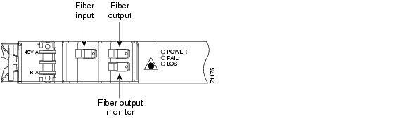
Connect the customer-supplied fiber optic patchcords to the SC/UPC optical ports of the ONS 15216 EDFA2 using the following procedure. Refer to Figure 3-1 while performing this procedure:
Step 1
Step 2
The measured optical output power should be approximately -3.5 dBm.
Step 3
a.
b.
Step 4
Figure 3-1 ONS 15216 EDFA2 Optical Connections
3.3.3 Optical Amplification Operation Verification Procedure
To verify ONS 15216 EDFA2 optical amplification, use the following procedure:
Step 1
Step 2
Step 3
For example, if the total input power is between -27 dBm and -5 dBm, expect an output power between -5 dBm and 17 dBm.
Table 3-1 Gain Range
22
-27
-5
-5
17
Note
3.4 Communications
The ONS 15216 EDFA2 can communicate in the following ways:
•
•
•
•
•
3.4.1 Alarm Out Relay Interface (RJ-45)
The ONS 15216 EDFA2 Alarm Out (RJ-45) port reports alarm status for the following:
•
•
•
These alarms can be connected to a network operations center (NOC) network management system (NMS) using the following methods:
•
•
Table 3-2 provides the ONS 15216 EDFA2 RJ-45 alarm out pinout and alarm definitions.
3.4.1.1 Alarm Relay Connection Procedure
To set up alarm contacts, follow these steps:
Step 1
Note
Step 2
a.
b.
Refer to Table 3-2 for information concerning alarm contacts. Refer to Alarm LEDs for information on the ONS 15216 EDFA2 alarm LEDs.
3.4.2 Alarm LEDs
The ONS 15216 EDFA2 has five LEDs:
•
•
•
•
Three of these LEDs, POWER, FAIL, and LOS, are located at the left side of the front panel of the ONS 15216 EDFA2. The two Ethernet LEDs are located at the top left and right sides of the Ethernet socket. When the module is powered on, an LED test is performed.
3.4.2.1 POWER LED (Green)
The POWER LED is green. This LED functions as follows:
•
•
•
In the off condition, the first pair of alarm relay contacts in the RJ-45 connector changes from a normally open condition to a closed condition. The LED and alarm automatically reset when the condition clears. (For additional alarm contact closure information, see the "Alarm Out Relay Interface (RJ-45)" section.)
3.4.2.2 FAIL LED (Red)
The FAIL LED is red. This LED functions as follows:
•
•
In the on condition, the second pair of alarm relay contacts in the RJ-45 connector changes from a normally open to a closed condition. If an invalid input optical signal is applied to the ONS 15216 EDFA2, the Fail LED is illuminated. The LED and alarm automatically reset when the condition clears.
3.4.2.3 LOS LED (Yellow)
The loss of signal (LOS) LED is yellow. This LED functions as follows:
•
•
In the on condition, the third pair of alarm relay contacts in the RJ-45 connector changes from a normally open condition to a closed condition. The LED and alarm automatically reset when the condition clears.
3.4.2.4 Ethernet Socket LEDs
Two LEDs are located at the top left and right sides of the Ethernet socket. These LEDs are both green. These LEDs function as follows:
•
•
3.4.3 Serial Interface (EIA/TIA-232) Communication
This section describes communication with the ONS 15216 EDFA2 using a serial connection.
3.4.3.1 Required Equipment
Establishing a serial communications link with a ONS 15216 EDFA2 requires the equipment listed in Table 3-3.
Table 3-3 Equipment Checklist
Laptop or computer running a Terminal application.
User-provided. HyperTerminal can be found in the Microsoft Windows Accessories menu.
EIA/TIA-232 cable with DB-9F/DB-9M connectors wired as shown in Figure 3-8.
Provides EIA/TIA-232 link to ONS 15216 EDFA2.
3.4.3.2 Serial Connection Procedure
To set up an EIA/TIA-232 link to the ONS 15216 EDFA2, use the following procedure. (The procedure uses HyperTerminal and a connection via the COM1 port.)
Step 1
Step 2
Step 3
Step 4
Step 5
Figure 3-2 HyperTerminal Connect To Dialog Box
Step 6
•
•
•
•
•
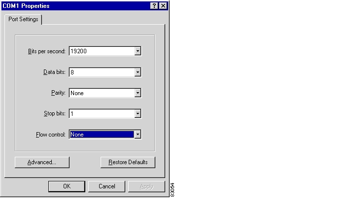
Click OK when done.
Figure 3-3 HyperTerminal COM1 Properties Dialog Box
Step 7
Step 8
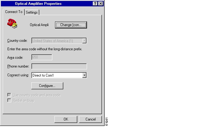
Figure 3-4 Optical Amplifier Properties Dialog Box (Connect To Tab)
Step 9
Step 10
Figure 3-5 Optical Amplifier Properties Dialog Box (Settings Tab)
Step 11
Figure 3-6 HyperTerminal ASCII Setup Dialog Box
Step 12
The ONS 15216 EDFA2 login screen appears. The appearance depends on the shell the ONS 15216 EDFA2 is set to (TL1 is the default shell). See the "Log In via RS-232 (EIA/TIA-232) Port Using HyperTerminal" section for the login procedure in ASH shell and the "Log In via RS-232 (EIA/TIA-232) Port Using HyperTerminal" section for the login procedure in TL1 shell.
3.4.4 Serial Interface Remote Communication via Modem
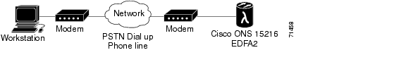
This section describes the procedure for establishing a remote dial-up connection to the ONS 15216 EDFA2. ONS 15216 EDFA2 remote communication requires two US Robotics 56K Fax modems set up to send data over a two-wire dial-up telephone line. (See Figure 3-7.)
This section assumes the use of the US Robotics 56K Fax modem V.90. Other modem types may require different settings to establish a remote dial-up connection. The user should review their modem documentation to ensure compatibility between US Robotics and other vendor modem types.
Figure 3-7 Remote Communication
3.4.4.1 Remote Communication Component Requirements
Table 3-4 lists the components required to communicate remotely with a ONS 15216 EDFA2. Table 3-4 is divided into two sections: Remote Site and Local Site. The Remote Site section lists components needed at the site that contains the ONS 15216 EDFA2 and the Local Site section lists components needed at the site where the user is located.
3.4.4.2 Modem Signals
The only signals required for communication are TXD (transmit), RXD (receive), and SIGNAL GROUND. By adjusting the modem manufacturer settings, the other signals can be ignored.
3.4.4.3 Modem Power Up
The modem has a DIP switch that overrides certain NVRAM settings during a power up. For consistent operation throughout the power cycles, the DIP switches must be set as displayed in Table 3-5.
3.4.4.4 Modem Configuration Settings
After configuring the DIP switch settings, each modem configuration must then be set using a terminal program such as Microsoft Windows HyperTerminal.
Connect the modem to the PC serial port using a DB-25M to DB-9F modem cable as per the manufacturer recommendations.
Set the terminal communication parameters as follows:
•
•
•
•
Table 3-6 gives a brief description of the modem settings that are stored in NVRAM. These settings survive power supply interruptions. Use these settings to configure each modem.
3.4.4.5 Setting and Saving Modem Settings
To set and save modem settings, enter the following command to the terminal program and to each modem:
atb0e0f1m1q1v1x1y0at&a3&b1&c1&d0&g0&h0&i0&k0s0=1at&m5&n8&7p1&r1&s1&t5&u8&y1s2=128at&w0
Note
3.4.4.6 PC Connection via Modem
The ONS 15216 EDFA2 and modem are connected through the RS-232 (EIA/TIA-232) port using a DB-9 connector. The modem, PC, and ONS 15216 EDFA2 should be physically set up as displayed in Figure 3-8. Use Figure 3-8 to properly connect the ONS 15216 EDFA2 to the modem.
Figure 3-8 DB-9 Pinout for RS-232 (EIA/TIA-232) Port
Using the terminal program from the PC, enter the ATDT command with the appropriate telephone number to call the remote ONS 15216 EDFA2 modem. After the modems synchronize, log into the ONS 15216 EDFA2 using the correct user name and password. Refer to "SNMP MIB Configuration," Chapter 6, "ASH Commands," and "TL1 Commands," for additional information on commands.
3.4.5 LAN Interface (Ethernet)
You can connect to the ONS 15216 EDFA2 to an Ethernet LAN for remote access.
Note
Telnet is an application that allows remote management using IP over the Ethernet LAN. The following types of commands can be issued through a Telnet session:
•
•
•
3.4.5.1 LAN Connection Procedure
Use the following procedure to configure the module to accept SNMP, CLI, and TL1 commands via its RJ-45 LAN port:
Step 1
Step 2
Use a straight-through Cat5 Ethernet cable with RJ-45 connectors to connect to a LAN, or use a cross-over cable if connecting directly to a PC.
Step 3
Note
Step 4
If you do not specify a port number, the ONS 15216 EDFA2 responds in the shell that the ONS 15216 EDFA2 is set to (TL1 is the default shell). Specify port number 8023 to access through the ASH shell or port number 3083 to access through the TL1 shell.
The ONS 15216 EDFA2 login screen appears. See the "Log In via RS-232 (EIA/TIA-232) Port Using HyperTerminal" section for the login procedure in ASH shell and the "Log In via RS-232 (EIA/TIA-232) Port Using HyperTerminal" section for the login procedure in TL1 shell.
![]()
![]()
![]()
![]()
![]()
![]()
![]()
![]()
Posted: Sun Apr 2 01:43:12 PST 2006
All contents are Copyright © 1992--2006 Cisco Systems, Inc. All rights reserved.
Important Notices and Privacy Statement.