|
|

Table Of Contents
Technical Specifications
This chapter discusses the technical specifications for the Cisco ONS 15216 EDFA2.
2.1 Optical Specifications
ONS 15216 EDFA2 optical specifications are listed and described in Table 2-1.
Table 2-1 ONS 15216 EDFA2 Optical Specifications
Input signal wavelength
1530 nm to 1563 nm
Input power (channel total)1
-27 dBm to 4 dBm (total all channels)
See the "Maximum Input Power" section and the "Channel Loading" section for more information.
Note
In the event of a fiber cut or loss of connection, and there is no input power, the ONS 15216 EDFA2 has -3.5 dBm of output power. For additional safety information, see the "Safety Requirements" section.
Mode of operation
Unidirectional (two common fibers: one transmit, one receive)
Maximum output power
17 ± 0.6 dBm
Signal gain per channel
13 dB to 22 dB
Channel gain deviation from setpoint
± 1.25 dB
Gain flattened
ONS 15216 EDFA2-A: < 1.5 dB (peak to valley)
ONS 15216 EDFA2: < 2 dB (peak to valley)
Maximum noise figure
ONS 15216 EDFA2-A: < 6 dB at 22 dB gain. See Table 2-2.
ONS 15216 EDFA2: < 7 dB at 22 dB gain
Polarization mode dispersion (PMD)
< 0.6 ps
Input/output optical return loss
> 27 dB
Backward ASE power
-30 dBm maximum
Polarization sensitivity
< 0.5 dB
Automatic gain control (AGC)
The ONS 15216 EDFA2 contains an active gain block with an automatic gain control loop to minimize the effects of output power variations per wavelength upon adding or deleting wavelengths on the same DWDM ring.
1 In Constant Output Power mode, the input power should not be less than -15 dBm to ensure that constant output power is maintained. It is also recommended that the minimum output power setting in this mode be no less than 13 dBm.
Table 2-2 Noise Figure Specification - ONS 15216 EDFA2-A Only
22
6.0
21
6.0
22
6.0
19
6.0
18
6.0
17
6.3
16
6.7
15
7.2
14
7.8
13
8.4
2.1.1 Maximum Input Power
The ONS 15216 EDFA2 operates at a gain setting between 13 and 22 dB. Each gain setting has a maximum input power. The maximum input power is defined as 17 dBm (the maximum output power) minus the gain setting. For example, at a gain setting of 22 dB, the maximum input power is -5 dBm. At a gain setting of 13 dB, the maximum input power is 4 dBm. Prolonged operation beyond the maximum input power can shorten the life of the ONS 15216 EDFA2.
External optical attenuators are required to reduce the total input power to less than or equal to 4 dBm.
2.1.2 Channel Loading
You can ensure a smooth upgrade path from a single channel to the maximum numbers of channels with a minimum disruption of service if the per-channel power of the single channel is properly set from the start. The per-channel power should be set so that at full channel loading, the total input power is less than the maximum power indicated in Table 2-3. For example, if the maximum number of channels at full loading is 18 and the gain is set to 22 dB, the maximum per channel power is -17.6 dBm.
Use Table 2-3 to calculate per-channel power as a function of the maximum total number of channels at full loading. Contact Cisco TAC with any questions or concerns regarding maximum input power or setting the upgrade path.
2.2 Electrical Specifications
The ONS 15216 EDFA2 uses a power supply that meets the electrical specifications listed in Table 2-4.
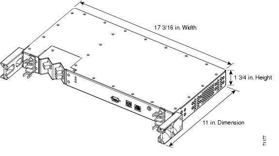
2.3 Mechanical Specifications
Table 2-5 lists the ONS 15216 EDFA2 mechanical specifications.
2.4 External Features
The ONS 15216 EDFA2 has the following external features:
•
•
•
•
•
•
•
•
•
•
•
Figure 2-1 displays a mechanical outline of the external features and dimensions of the ONS 15216 EDFA2.
Figure 2-1 ONS 15216 EDFA2 Dimensions
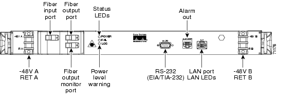
2.5 Front Panel
Figure 2-2 shows the ONS 15216 EDFA2 front panel in detail. The front panel provides an all-front access (fibers, power, alarm contact, and management interface) that complies with international standards.
Figure 2-2 ONS 15216 EDFA2 Front Panel
Table 2-6 describes the ONS 15216 EDFA2 front panel features.
Table 2-6 ONS 15216 EDFA2 Front Panel Features
Terminal strip
Terminal strip for supplying power to the ONS 15216 EDFA2. Attach AWG 18 stranded power wires to appropriate terminals.
Threaded grounding holes
Threaded grounding holes (#10-32) to ground the ONS 15216 EDFA2.
Alarm Out
RJ-45 connector used for alarm system connection. (See the "Alarm Out Relay Interface (RJ-45)" section for additional information.)
Serial port connection (EIA/TIA-232)
Serial port for local or remote (modem) data communication connection. (See "Installation" for additional information.)
Label
Laser warnings, designation labels, and power level warning.
Status LEDs
LEDs indicating status of power, fail, loss of signal, Ethernet link availability and Ethernet link traffic. (See the "Alarm LEDs" section.)
Fiber input
SC/UPC fiber input port.
Fiber output
SC/UPC fiber output port.
Monitor output
SC/UPC port for fiber that taps off 1% of output signal for monitoring purposes.
Chassis ground lugs
Rear panel chassis ground to attach ground lug or wires using #10-32 screws to the ONS 15216 EDFA2-A (#8-32 nut to the ONS 15216 EDFA2)
LAN
RJ-45 connector used for 10BASE-T Ethernet connection. For more information, see the "LAN Interface (Ethernet)" section.
![]()
![]()
![]()
![]()
![]()
![]()
![]()
![]()
Posted: Sun Apr 2 01:37:00 PST 2006
All contents are Copyright © 1992--2006 Cisco Systems, Inc. All rights reserved.
Important Notices and Privacy Statement.