|
|

This chapter describes how to use the Cisco ONS 15200 web interface to view alarms and events for the ONS 15200 system.
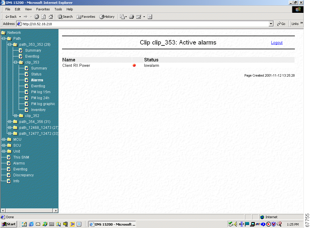
The CLIP Active alarms screen provides a list of active alarms for the selected Client Layer Interface Port (CLIP) module (Figure 4-1). The CLIP Active alarms screen has two columns: Name and Status. Table 4-1 describes the alarms that can appear in the Name column.
| Alarm Name | Definition |
|---|---|
DWDM A RX Power (protected only) | Indicates that the power input on side A of the ONS 15200 network is outside the acceptable range |
DWDM B RX Power (protected only) | Indicates that the power input on side B of the ONS 15200 network is outside the acceptable range |
DWDM B RX Power (unprotected only) | Indicates that the power input on the ONS 15200 network is outside the acceptable range |
DWDM Peltier Current | Indicates that the Peltier current of the selected CLIP module is outside the acceptable range |
DWDM Laserbias | Indicates that the value of the current used to control laser modulation is not within the specified range |
DWDM LOC | Indicates that the working/protection or working channel is lost |
DWDM FDI Alarm | Indicates whether a switching action to the protection path has taken place (Forward Defect Indication) |
DWDM Laser Temp | Indicates that the temperature of the laser transmitting to the ONS 15200 network is outside the acceptable range |
Client RX Power | Indicates that the power input from the client equipment is outside the acceptable range |
Client Laserbias | Indicates that the value of the current used to control laser modulation is not within the specified range |
BOARD Board Temp | Indicates that the temperature on the surface of the CLIP module circuit board is outside the acceptable range |
BOARD Power Alarm | Indicates that the PS-1or the PS-2 input is outside the acceptable range |
QPPA (protected only) | Indicates a proprietary protocol error on the A-side of the network |
QPPB (protected only) | Indicates a proprietary protocol error on the B-side of the network |
QPP (unprotected only) | Indicates a proprietary protocol error |
CAN | Indicates an error on the CAN bus |
Table 4-2 describes the values displayed in the Status column. LEDs located next to the status indicate the severity of the alarm.
| Alarm Name | Definition |
|---|---|
highalarm | A CLIP module recorded an event in which an upper alarm threshold was crossed |
lowalarm | A CLIP module recorded an event in which a lower alarm threshold was crossed |
highwarning | A CLIP module recorded an event in which an upper warning threshold was crossed |
lowwarning | A CLIP module recorded an event in which a lower warning threshold was crossed |
Table 4-3 describes the LEDs.
| Alarm Name | Definition |
|---|---|
Red | Critical or major alarm—The condition reported by the alarm affects traffic. |
Yellow | Minor alarm or warning—The condition reported by the alarm could affect the quality of service, but does not threaten the continuity of service. |
The CLIP Eventlog screen displays a list of events that have occurred in relation to the selected CLIP module (Figure 4-2).
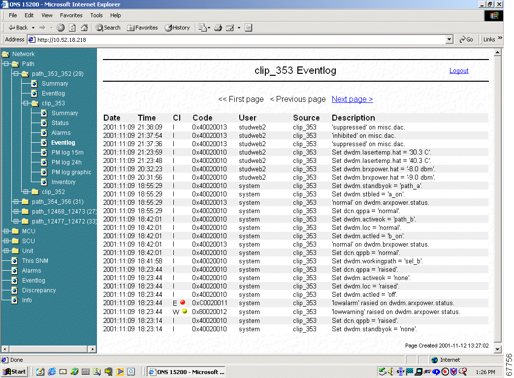
Table 4-4 describes the information provided on the CLIP Eventlog screen.
| Alarm Name | Definition |
|---|---|
Date | Displays the date (yyyy-mm-dd) where the selected event occurred. |
Time | Displays the time (hh:mm:ss) where the selected event occurred. |
CI | Class displays an LED indicating the severity of the alarm:
|
Code | Displays the internal code assigned to the event. |
User | Displays the user name of the person that performed the selected activity. Activities initiated automatically are logged as system. |
Source | Displays the name of the module where the activity was initiated. |
Description | Displays a description of the event. |
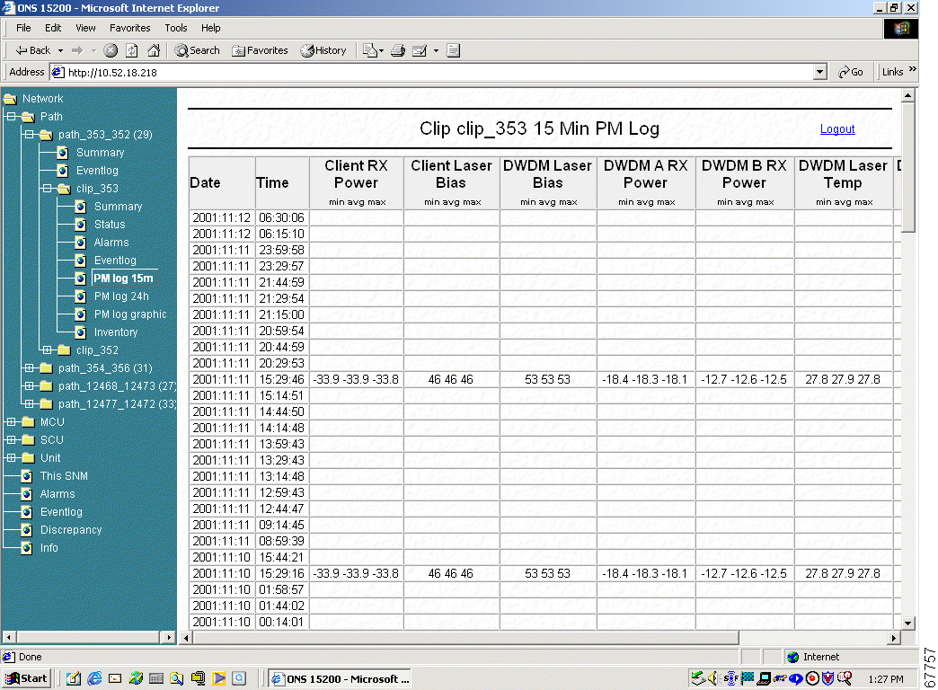
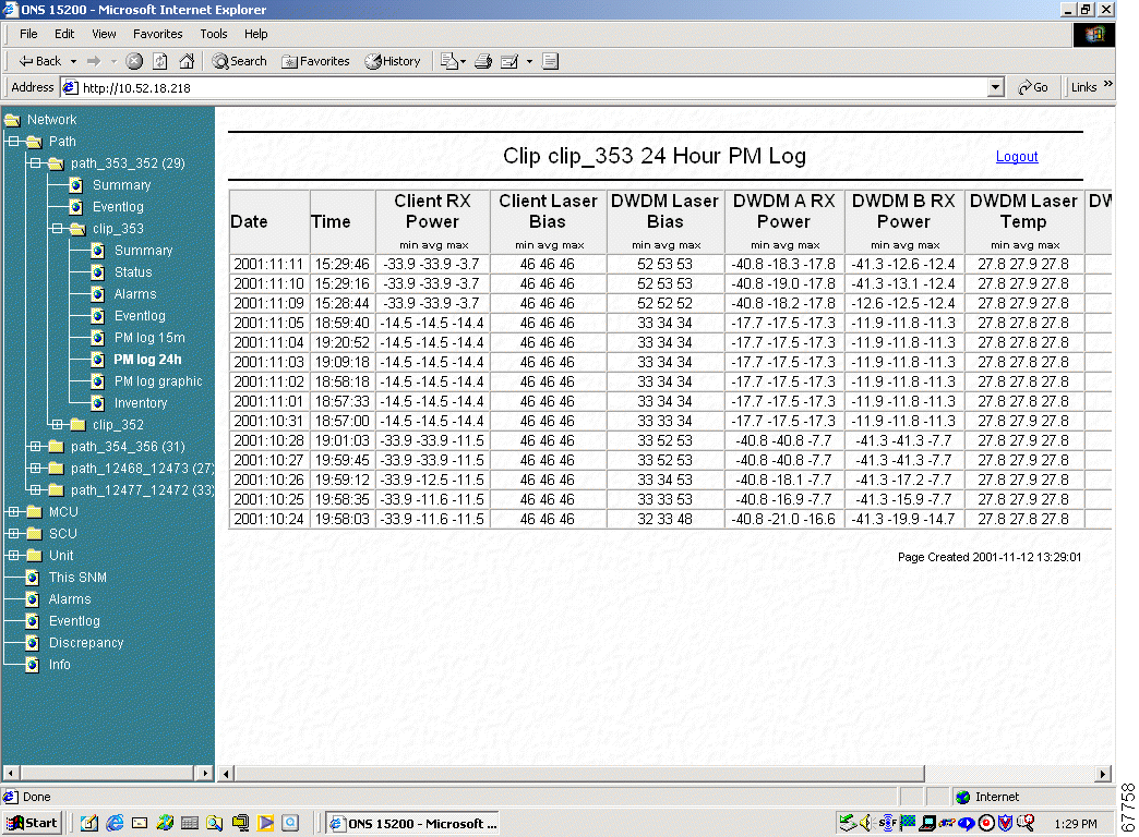
The Performance Monitor screen displays a list of measurements that have occurred in relation to the selected CLIP module.
The Performance Monitor (PM log 15m) screen provides a list of measurements for the selected CLIP module (Figure 4-3). All measurements are displayed in 15 minutes intervals.
The Performance Monitor (PM log 24h) screen provides a list of measurement for the selected CLIP module (Figure 4-4). All measurements are displayed in 24 hour intervals.
The Performance Monitor (PM log graphic) screen displays the measurement for the selected CLIP module (Figure 4-5).
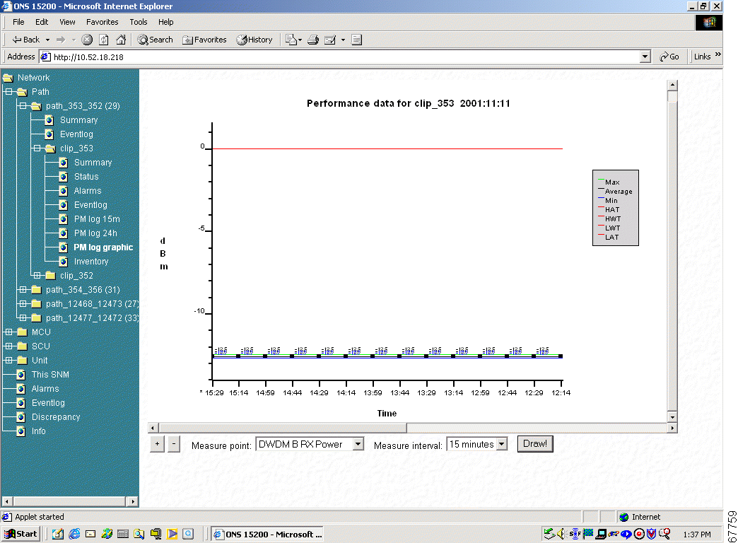
Step 2 Choose the Measure interval from the pull down menu.
Step 3 Click the Draw Button.
 |
Note After a few moments the graphic displays. |
Step 4 Choose the Zoom button to change the display area.
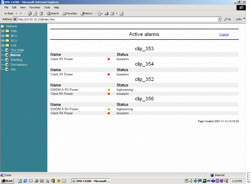
The Active Alarms screen provides a summary of active alarms for all CLIP modules (Figure 4-6).
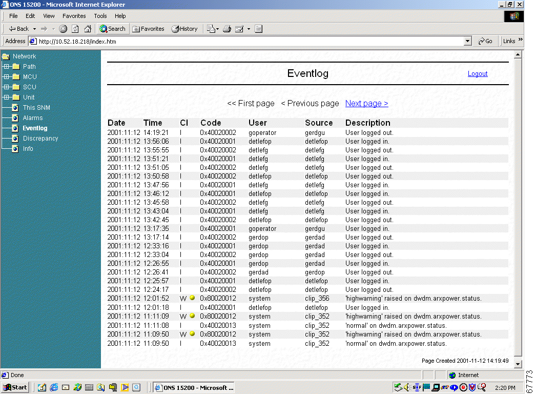
The Eventlog screen displays a list of events that have occurred in the system (Figure 4-7).
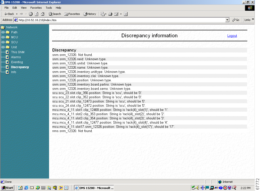
The Discrepancy Information screen (Figure 4-8) displays the difference between the configuration which is saved in the EEPROM and the real configuration found by the system software.
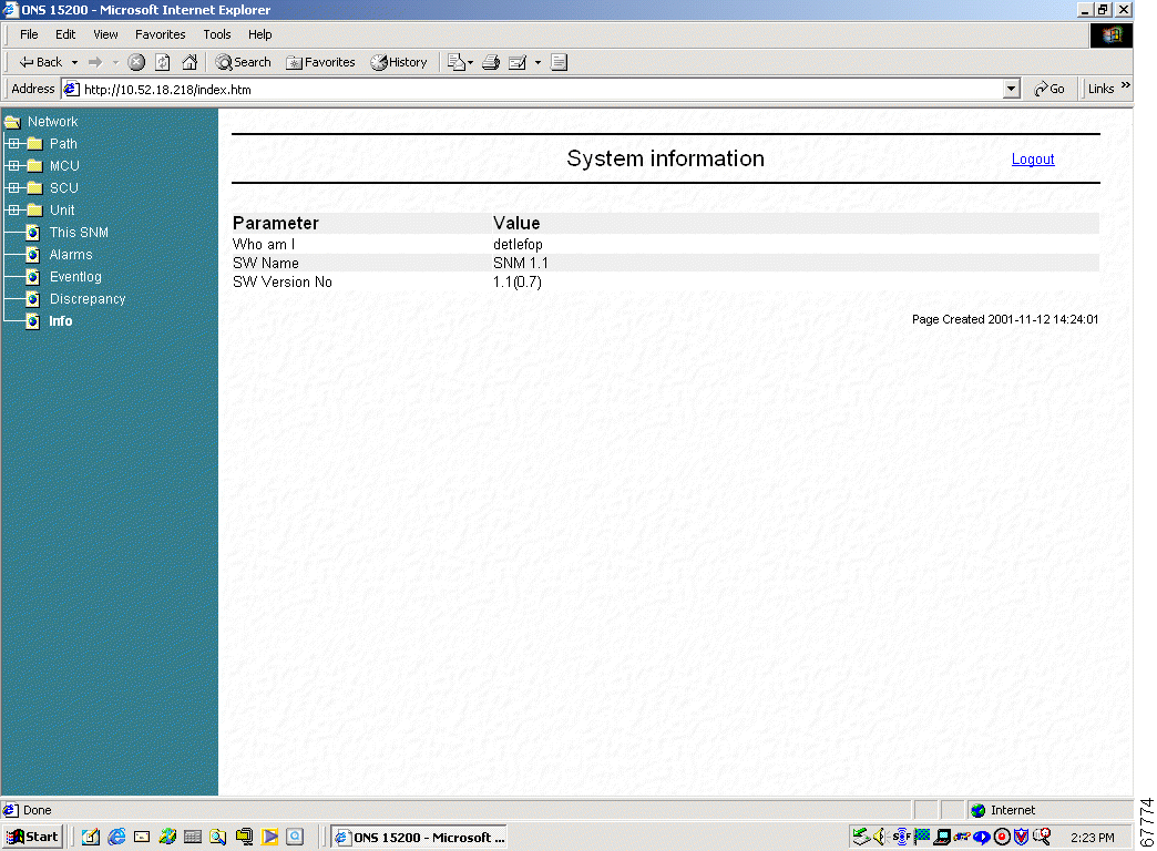
The System Information screen gives a short system overview (Figure 4-9).
| Parameter | Definition |
|---|---|
Who am I | Shows the login user |
SW Name | Displays the software name and version |
SW Version No | Displays the software and review version |
![]()
![]()
![]()
![]()
![]()
![]()
![]()
![]()
Posted: Fri Jan 4 16:51:24 PST 2002
All contents are Copyright © 1992--2002 Cisco Systems, Inc. All rights reserved.
Important Notices and Privacy Statement.