|
|

This chapter provides a general overview of the Cisco ONS 15200 web interface.
To use the Cisco ONS 15200 web-based interface, you need a PC with a web browser (Internet Explorer 5.5 or higher, or Netscape 4.5 or 4.7), a 10BaseT Ethernet interface, and IP access. For the PC requirements refer to the vendor documentation.
The following list describes the features of the ONS 15200 web interface:
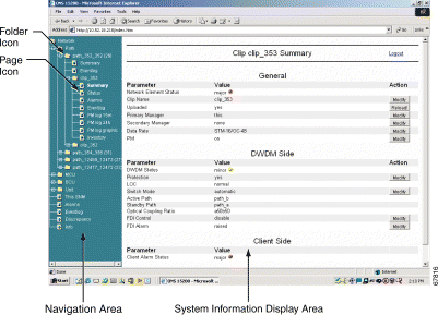
The ONS 15200 web interface runs in a Java-enabled browser. The screen (window) is divided into two sections (panes). Use the navigation area on the left of the screen to view the ONS 15252 Multichannel Unit (MCU), the ONS 15201 Single-Channel Unit (SCU), installed modules, event logs, and alarm logs. The display area on the right of the screen shows information specific to each MCU, SCU, module, or log. See Figure 1-1 for an example of the ONS 15200 web interface window.
You can make a direct connection to the system, through an ONS 15252 MCU, or an indirect connection, through customer equipment. For further information see the "Connect Directly to the ONS 15252 MCU" procedure and the "Connecting with a LAN or WAN" section. When the computer is configured and connected, perform the following procedure.
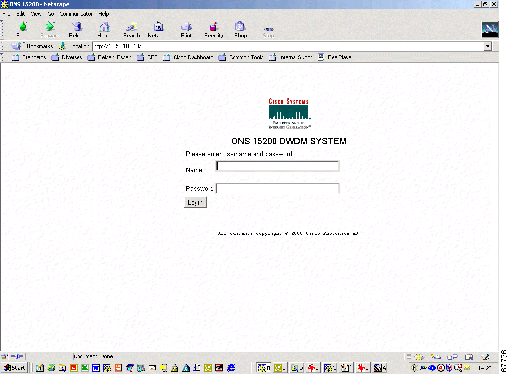
Step 2 The system will reply with the screen shown in Figure 1-2.
Step 3 Type your user name (with operator rights or guest rights) and password as shown in Figure 1-2.
Step 4 The system replies with the welcome screen shown in Figure 1-3.

Click the folder or page icons in the navigation area to navigate to different screens. Click a folder to expand it to display pages and subfolders. Click a page to display the relevant information in the system information display area.
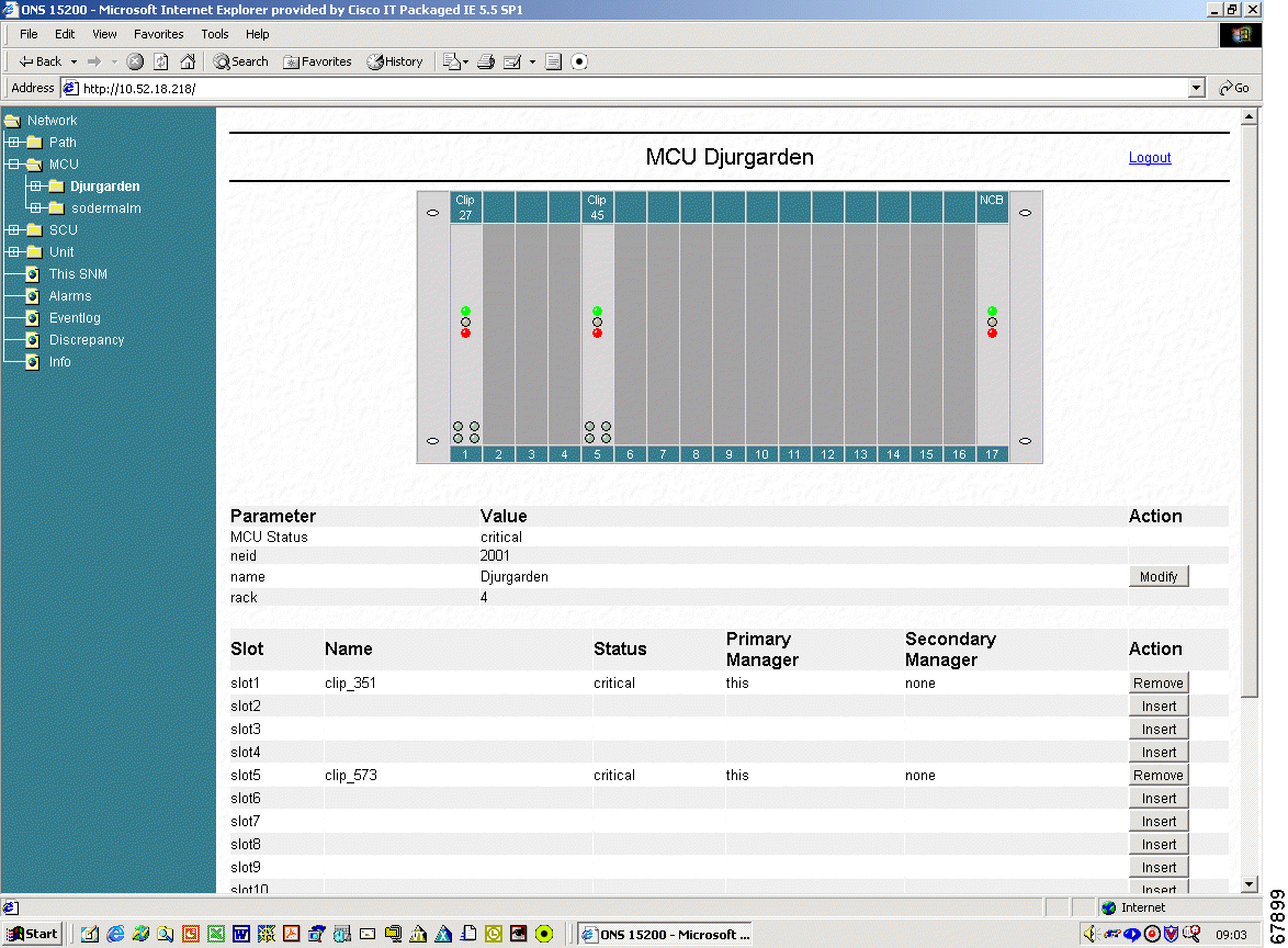
Click MCU to display an MCU overview with all current MCUs (Figure 1-4). Click the MCU or SCU folder to display subfolders. Click the name of the subfolder to view a graphical representation of the network element (NE). Click a module in the NE to display summary information for the selected module.
This section describes how to display network information and interpret the messages and measurements.
Figure 1-5 displays a graphical overview of an MCU and includes a short description of each installed module.
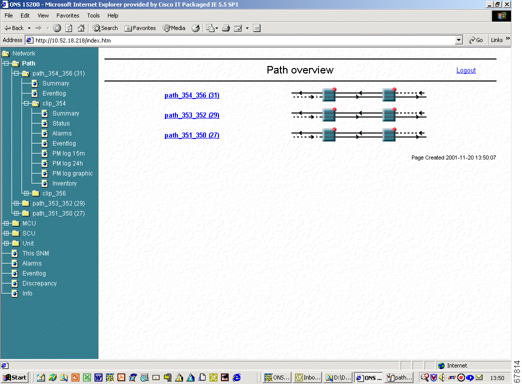
The Path Overview screen provides a graphical overview of all paths between the network elements in an ONS 15200 system (Figure 1-6). Icons display the working path, protect path, network elements, and alarms. Icons on the Path Overview screen provide shortcuts to summary and status screens.
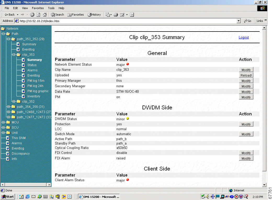
The information available on the CLIP Summary screen varies depending on the configuration of the associated Client Layer Interface Port (CLIP) module (protected or unprotected). See "ONS 15200 Configurations" for more information about each parameter. Figure 1-7 shows the CLIP Summary screen for a protected CLIP module.
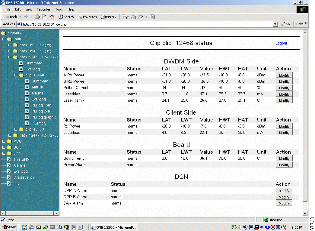
The information available on the CLIP Status screen varies depending on the configuration of the associated CLIP module (protected or unprotected). See "ONS 15200 Configurations" for more information regarding each parameter. Figure 1-8 shows the CLIP Status screen for a protected CLIP.
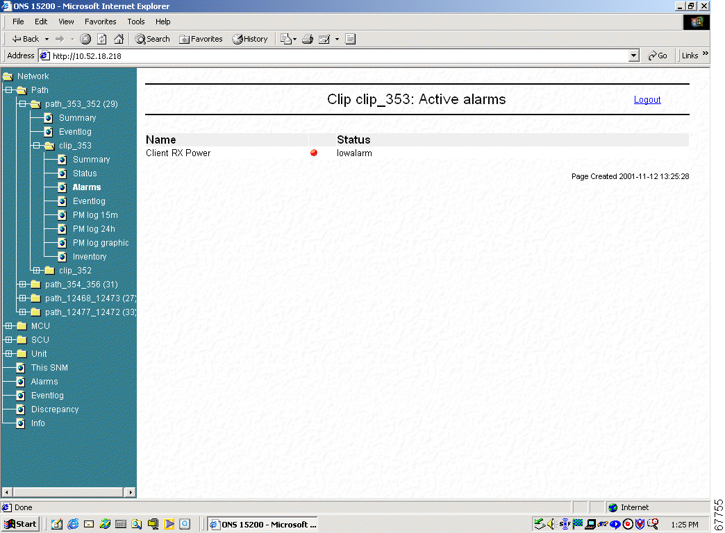
The Alarms screen provides a list of all active alarms (Figure 1-9). Alarm screens are available for each CLIP module or for the complete system. See "ONS 15200 Configurations" for more information regarding each parameter.
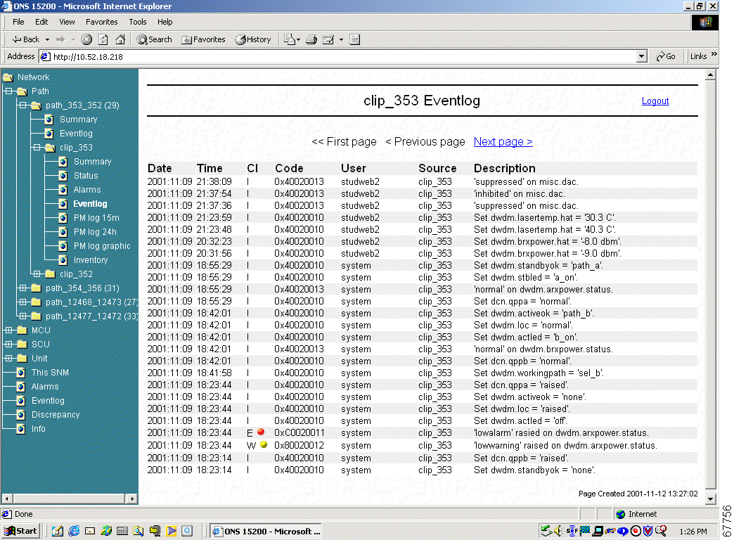
The Event Log screen provides a tabular list of events for the selected CLIP. The information in Figure 1-10 is provided. See "ONS 15200 Configurations" for more information about each parameter.
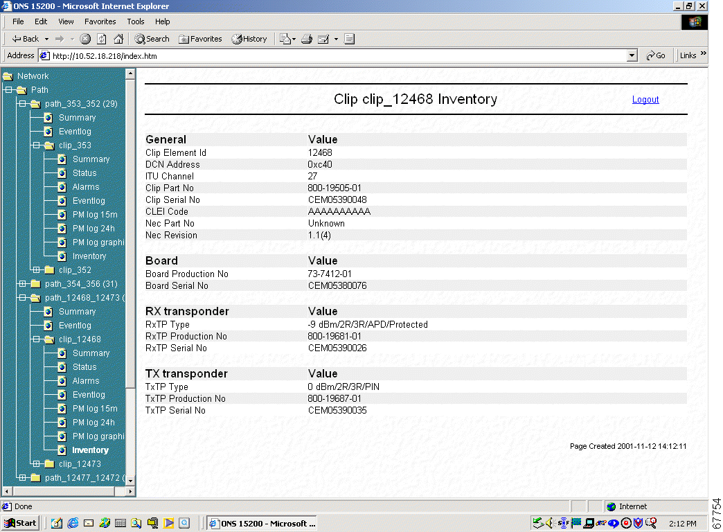
The CLIP Inventory screen lists the CLIP modules installed in the NE (Figure 1-11).
The Unit folder provides another method to access the CLIP and NCB modules installed in the ONS 15200 system. Modules listed in the Unit folder are sorted by unit name rather than by the NE.
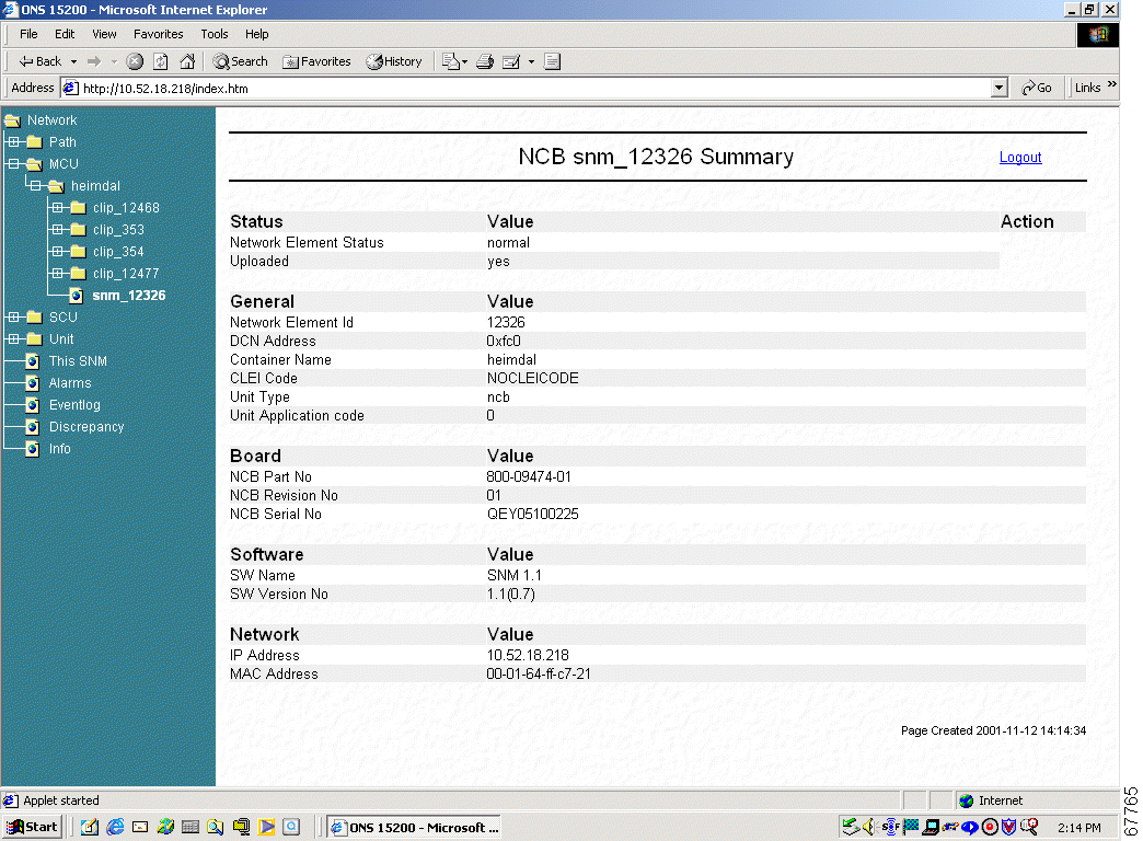
The NCB screen displays a tabular list of NCB module information.
![]()
![]()
![]()
![]()
![]()
![]()
![]()
![]()
Posted: Fri Jan 4 16:04:41 PST 2002
All contents are Copyright © 1992--2002 Cisco Systems, Inc. All rights reserved.
Important Notices and Privacy Statement.