|
|

The Cisco Metro 1500 series system can be equipped with an optional remote switch module (RSM). It is a plug-in module that enhances the system with 1+1 line protection capabilities.
The RSM is an optical switch. Both fibers of the band splitter module (BSM) remote line are connected to the RSM. The RSM links the communication to one of its remote lines with two fibers each. The active line of the RSM operates as the standard communication path and the other line is the backup path. The backup line is observed continuously. If communication is interrupted in the standard line, the RSM links the communication to the backup line automatically. Switching occurs in less than 50 ms. After switching, the former backup line, now the active line, operates as the standard line and the broken line becomes the backup line. The RSM does not switch back when the backup line recovers.
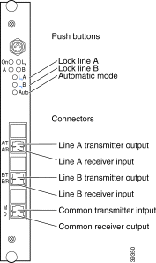
The RSM can be controlled locally with pushbuttons at the front panel and remotely using NEMI and network management software. Figure 8-1 shows the RSM front panel.

Three pushbuttones control the RSM. Table 8-1 describes each pushbutton and its function.
| Label | Description |
|---|---|
Lk A | Locks the RSM on line A |
Lk B | Locks the RSM on line B |
Auto | Switches the RSM to automatic mode |
Four LEDs indicate the status of the RSM. Table 8-2 describes the LEDs.
| Label | Color | Description |
|---|---|---|
On | Green | Power is on. No error was detected. |
Red, continuous | A hardware error was detected. | |
Red, blinking | Loss of signal was detected on both remote lines of the RSM. Both remote lines are broken or a hardware error was detected. | |
A | Green | Line A is active. |
Green, blinking | Line A is inactive. A takeover of the communication is possible. | |
Red | Line A is broken. | |
B | Green | Line B is active. |
Green, blinking | Line B is inactive. A takeover of the communication is possible. | |
Red | Line B is broken. | |
Lk | Yellow | RSM is locked to one line. No automatic switching is possible. |
Table 8-3 shows the six optical connectors of the RSM. Figure 8-1 shows the front panel of the RSM.
| Label | Description |
|---|---|
A/T | Line A transmitter |
A/R | Line A receiver |
B/T | Line B transmitter |
B/R | Line B receiver |
D | Transmitter output to the BSM |
M | Receiver input from BSM |
All connectors are of the MiniSC type.
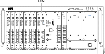
To add or replace a RSM to the primary chassis (Figure 8-2), follow these instructions:

 |
Warning Only trained and qualified personnel should be allowed to install, replace, or service this equipment. |
 |
Note Before connecting the fiber cable, remove the dust covers and blind plugs and clean the fiber ferules. The minimum bend radius of optical fiber cables is about 30-50 mm. Avoid tight or pressed fibers. |
Step 2 Follow this step if you are replacing a RSM. Disconnect all jumpers and protect the connectors with dust covers (jumpers) and blind plugs (RSM).
Step 3 Loosen the two screws from the front panel of RSM or the blank filler module.
Step 4 Take the new RSM from the shipping container and apply dry and oilfree air to blow out any dust particles.
Step 5 Carefully insert the RSM into the chassis slot while guiding the upper and lower edges of the module in the tracks until its connectors come into contact with the backplane connectors. A force of up to 1 lb (4.5 newton) is required to push the module completely into the chassis.
 |
Caution It is critical to insert the module gently. If a force greater than 1 lb (4.5 newton) is needed to push in the RSM, stop immediately. Inspect the electrical connector. If the connector is not damaged, repeat the insertion procedure. |
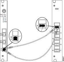
Step 6 Follow this step if you are adding a RSM. Connect a MiniSC jumper to the "M" labeled connector of the BSM.
Step 7 Connect the other end of the jumper to the "M" labeled connector of the RSM as shown in Figure 8-3.

Step 8 Follow this step if you are adding a RSM. Connect a MiniSC jumper to the "D" labeled connector of the BSM.
Step 9 Connect the other end of the jumper to the "D" labeled connector of the RSM as shown in Figure 8-3.
Step 10 Connect the MiniSC plug of the "Transmission Fiber of Line A" labeled remote line to the "A/T" labeled connector of the RSM as shown in Figure 8-4.

Step 11 Connect the MiniSC plug of the "Receiver Fiber of Line A" labeled remote line to the "A/R" labeled connector of the RSM as shown in Figure 8-4.
Step 12 Connect the MiniSC plug of the "Transmission Fiber of Line B" labeled remote line to the "B/T" labeled connector of the RSM as shown in Figure 8-4.
Step 13 Connect the MiniSC plug of "Receiver Fiber of Line B" labeled remote line to the "B/R" labeled connector of the RSM as shown in Figure 8-4.
Step 14 Place the cables in the cable tray at the bottom of the chassis.
Step 15 Mount the cover in front of the chassis.
If all lines are connected and the signals applied well to the RSM, the RSM operates in Automatic Mode. The "On" LED (green) and the "A" LED (green) are illuminated and the "B" LED is blinking.
If you have any problems which result in a deviation from the installation described above, please contact your Service Representative immediately.
The RSM supports two operation modes: automatic mode and lock mode. Switching between the modes can be done by pushing the appropriate button on the RSM front panel.
At shipping time the RSM is set to automatic mode and line A is the active line. Line B is the backup line. By default, the RSM saves its last setting in the event of a power loss.
If line A breaks, the RSM monitors the accessibility of the backup line. If the backup line (line B) is functional, the RSM links the communication to line B. The RSM then starts to monitor line A. When line A recovers, switching the lines back does not take place. Line B continues to operate as the active line and line A as the backup line.
If line B is active and it breaks, the RSM monitors the accessibility of the backup line. If the backup line (line A) is functional, the RSM links the communication to line A. The RSM starts to monitor line B. After line B recovers, switching the lines back does not take place. Line A continues to operate as the active line and line B as the backup line.
At any time the RSM can be switched from automatic mode to lock mode.
The RSM monitors the accessibility of the backup line. If line A breaks and if line B is functional, the RSM links the communication to line B.
If line A is the active line and you lock the RSM to line B, the RSM checks the accessibility of line B. If line B is functional, the RSM switches the communication to line B and holds the communication on this line. Automatic switching to the backup line (line A) is stopped. In the case of a broken line B, the RSM cannot be locked to line B.
If line B is the active line and you lock the RSM on line B, no switching takes place. The communication is locked on line B. Any automatic switching to the backup line (line A) is prohibited.
If line B is the active line and you lock the RSM to line A, the RSM checks the accessibility of line A. If line A is functional the RSM switches the communication to line A and holds the communication on this line. Any automatic switching to the backup line (line A) is avoided. In case of a broken line A, the RSM is not lockable on line A.
At any time the RSM can be switched from lock mode to automatic mode.
If neither line A or line B is connected to the RSM or both lines are broken, the On LED indicates this status by a blinking red light. Also the A and B LEDs are red as a visual signal to check for disconnected lines.
![]()
![]()
![]()
![]()
![]()
![]()
![]()
![]()
Posted: Tue Jan 23 11:18:11 PST 2001
All contents are Copyright © 1992--2001 Cisco Systems, Inc. All rights reserved.
Important Notices and Privacy Statement.