|
|

Table Of Contents
Troubleshooting 2.5-Gbps Transponder Module Problems
5.2 Initial Troubleshooting Checklist
5.3 Cabling the 2.5-Gbps Transponder Module
5.3.1 Direct Cabling Using MTP-to-MTP Cables
5.3.2 Cross Connect Drawer Cabling Using MTP-to-8-MU Cables
5.4 Troubleshooting 2.5-Gbps Transponder Module Interface Problems
5.4.1 Transponder Module Not in show hardware Command Output
5.4.2 Wave Interface Is Down and Shows Loss of Light
5.4.3 Transparent Interface Is Down and Shows Loss of Light
5.4.4 Active Wavepatch Interfaces Down Due to Loss of Light
5.4.5 Wave Interface Shows Loss of Lock
5.4.6 Transparent Interface Shows Loss of Lock
5.4.7 Interface Shows Loss of Sync
5.4.8 Interface Shows Loss of Frame
5.4.9 Active Wavepatch Interfaces Down Due to Low Alarm
5.4.10 Unable to Configure Protocol Encapsulation or Clock Rate
5.5 Troubleshooting 2.5-Gbps Transponder Module Problems Using Loopbacks
5.5.1 Physical Fiber Loopbacks
5.5.2 Client Signal Software Loopbacks
5.5.3 Trunk Software Loopbacks
Troubleshooting 2.5-Gbps Transponder Module Problems
This chapter describes how to troubleshoot 2.5-Gbps transponder module problems. This document contains the following sections:
•
Overview
•
•
•
•
5.1 Overview
The 2.5-Gbps transponder module on the Cisco ONS 15540 ESPx converts the client signal to an ITU-compliant wavelength, which is cross-connected over the optical backplane to the mux/demux modules. A single system can hold up to eight 2.5-Gbps line card motherboards, each of which accepts four 2.5-Gbps transponder modules.
There are two types of 2.5-Gbps line card motherboards, splitter and nonsplitter.
The 2.5-Gbps line card motherboards support three types of transponder modules: SM (single-mode), MM (multimode), and Type 2 extended range with SFP optics.
The client interfaces on the SM transponder modules and MM transponder modules are protocol transparent and bit-rate transparent, and accept either single-mode or multimode client signals on the 1310-nm wavelength through SC connectors. The multimode transponder module supports 62.5 Βm MM, 50 Βm MM, and 9 or 10 Βm SM fiber; the single-mode transponder module supports 50 Βm MM fiber and 9 or 10 Βm SM fiber.
The Type 2 extended range transponder module accepts two types of SFP optics:
•
•
Fixed rate SFP optics modules support specific protocols. Variable rate SPF optics modules support a range of clock rates. For detailed information about interface configuration, refer to the
Cisco ONS 15540 ESPx Configuration Guide. For information on transceiver specifications, refer to the Cisco ONS 15540 ESPx Hardware Installation Guide.5.2 Initial Troubleshooting Checklist
Follow this initial checklist before proceeding with the troubleshooting procedures:
•
•
•
•
•
•
•
•
•
•
•
•
•
5.3 Cabling the 2.5-Gbps Transponder Module
Correctly connecting the 2.5-Gbps transponder module is very important to avoid problems. You can connect the 2.5-Gbps transponder module to a mux/demux module either directly using an MTP-to-MTP cable or through the cross connect drawer using MTP-to-8-MU cables.
5.3.1 Direct Cabling Using MTP-to-MTP Cables
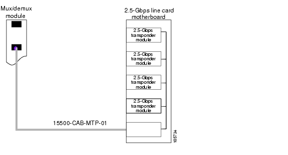
The MTP-to-MTP cable for the 2.5-Gbps line card motherboard is the 15500-CAB-MTP-01 (blue) cable. Use it to directly connect the 2.5-Gbps transponder modules to the mux/demux module. See Figure 5-1.
Figure 5-1 MTP-to-MTP Cabling Example
5.3.2 Cross Connect Drawer Cabling Using MTP-to-8-MU Cables
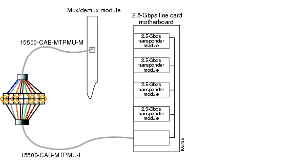
The MTP-to-8-MU cables for the 2.5-Gbps line card motherboard are the 15500-CAB-MTPMU-M (grey) and the 15500-CAB-MTPMU-L (green) cables. Figure 5-2 shows an example of how to connect the 2.5-Gbps line card motherboard to the cross connect drawer.
Figure 5-2 Cross Connect Drawer Cabling Using MTP-to-8-MU Cables
5.4 Troubleshooting 2.5-Gbps Transponder Module Interface Problems
This section contains troubleshooting procedures for 2.5-Gbps transponder module interface problems.
5.4.1 Transponder Module Not in show hardware Command Output
Symptom Transponder module is not listed in the show hardware command output.
Table 5-1 describes the potential causes of the symptom and the solutions.
5.4.2 Wave Interface Is Down and Shows Loss of Light
Symptom The wave interface is down and shows Loss of Light.
Table 5-2 describes the potential causes of the symptom and the solutions.
5.4.3 Transparent Interface Is Down and Shows Loss of Light
Symptom The transparent interface is down and shows Loss of Light.
Table 5-3 describes the potential causes of the symptom and the solutions.
5.4.4 Active Wavepatch Interfaces Down Due to Loss of Light
Symptom The active wavepatch interfaces are down due to Loss of Light.
Table 5-4 describes the potential causes of the symptom and the solutions.
5.4.5 Wave Interface Shows Loss of Lock
Symptom The wave interface shows Loss of Lock.
Table 5-5 describes the potential causes of the symptom and the solutions.
5.4.6 Transparent Interface Shows Loss of Lock
Symptom The transparent interface shows Loss of Lock.
Table 5-6 describes the potential causes of the symptom and the solutions.
5.4.7 Interface Shows Loss of Sync
Symptom The wave or transparent interface shows Loss of Sync.
Table 5-7 describes the potential causes of the symptom and the solutions.
5.4.8 Interface Shows Loss of Frame
Symptom The wave or transparent interface shows Loss of Frame (applies to SONET/SDH encapsulations only).
Table 5-8 describes the potential causes of the symptom and the solutions.
5.4.9 Active Wavepatch Interfaces Down Due to Low Alarm
Symptom The active wavepatch interfaces are down due to low alarm.
Table 5-9 describes the potential causes of the symptom and the solutions.
5.4.10 Unable to Configure Protocol Encapsulation or Clock Rate
Symptom The CLI (command-line interface) rejects the protocol encapsulation or clock rate for the transparent interface.
Table 5-10 describes the potential cause of the symptom and the solution.
5.5 Troubleshooting 2.5-Gbps Transponder Module Problems Using Loopbacks
This section describes how to perform fault isolation on 2.5-Gbps transponder modules using the following types of loopbacks:
•
•
•
5.5.1 Physical Fiber Loopbacks
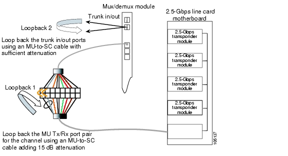
You can use physical fiber loopbacks at various places to check the connectivity and isolate a bad or dirty fiber. Using an SC-to-MU cable with a 15 dB attenuator, you can set up a loopback in the cross connect drawer for the MU pair of the channel being verified. This ensures that the connectivity between the 2.5-Gbps transponder module through the 2.5-Gbps line card motherboard onto the MTP-to-8-MU fiber is good (see Loopback 1 in the example in Figure 5-3). You can also loop back the multiplexed trunk fiber coming out of the trunk port in/out interfaces of the mux/demux module. This loopback verifies the connectivity from the 2.5-Gbps transponder module through the cross connect drawer and the mux/demux module (see Loopback 2 in the example in Figure 5-3).
Figure 5-3 Physical Fiber Loopback Examples
5.5.2 Client Signal Software Loopbacks
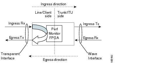
A client signal software loopback verifies the functioning between the client equipment and the 2.5-Gbps transponder module (see Figure 5-4).
Figure 5-4 Client Signal Loopback Example on a 2.5-Gbps Transponder Module
Procedure: Create a Client Signal Software Loopback
Step 1
Step 2
Step 3
5.5.3 Trunk Software Loopbacks
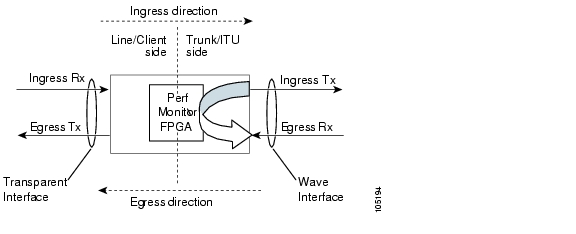
A trunk software loopback verifies the functioning of the 2.5-Gbps transponder module on the trunk side (see Figure 5-5). With this feature, you can verify the communication between two 2.5-Gbps transponder modules.
Figure 5-5 Trunk Side Loopback Example on a 2.5-Gbps Transponder Module
Procedure: Create a Trunk Software Loopback
Step 1
Step 2
Step 3
![]()
![]()
![]()
![]()
![]()
![]()
![]()
![]()
Posted: Thu Feb 16 04:36:34 PST 2006
All contents are Copyright © 1992--2006 Cisco Systems, Inc. All rights reserved.
Important Notices and Privacy Statement.