|
|

Table Of Contents
Troubleshooting 10-GE Transponder Module Problems
6.2 Initial Troubleshooting Checklist
6.3 Cabling the 10-GE Transponder Module
6.3.1 Direct Cabling Using MTP-to-MTP Cables
6.3.2 Direct Cabling Using MTP-to-2-MTP Cables
6.3.3 Cross Connect Drawer Cabling Using MTP-to-4-MU Cables
6.4 Troubleshooting 10-GE Transponder Module Interface Problems
6.4.1 Tengigethernetphy Interface Down and Shows Loss of Lock
6.4.2 Waveethernetphy Interface Down and Shows Loss of Lock
6.4.3 Waveethernetphy Interface Down and Shows Loss of Sync
6.4.4 Ethernetdcc Interface Down
6.4.5 Tengigethernetphy Interface Shows CVRD Errors
6.4.6 Waveethernetphy Interface Shows CVRD Errors
6.5 Troubleshooting 10-GE Transponder Module Problems Using Loopbacks
6.5.1 Physical Fiber Loopbacks
6.5.2 Client Signal Software Loopbacks
6.5.3 Trunk Software Loopbacks
Troubleshooting 10-GE Transponder Module Problems
This chapter describes how to troubleshoot 10-GE transponder module problems. This document contains the following sections:
•
Overview
•
•
•
•
6.1 Overview
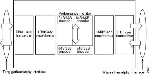
The 10-GE transponder module on the Cisco ONS 15540 ESPx implements the 10GBASE-LR IEEE 802.3ae standard. It supports connections to a Cisco ONS 15530 1310-nm 10-Gbps uplink card acting as a downlink and connections to a native 10GBASE-LR or a 10GBASE-ER IEEE 802.3ae MAC implementation. The 10-GE transponder module has one short reach 1310-nm laser on the client side and an ITU DWDM 1550-nm laser at the trunk side.
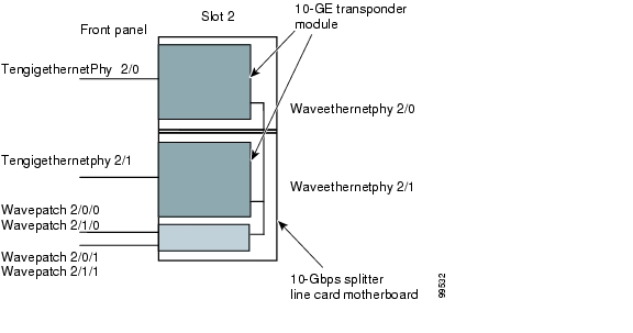
The 10-Gbps line card motherboard has two half-sized subslots that can accommodate two 10-GE transponder modules. There are two types of 10-Gbps line card motherboards, splitter and nonsplitter.
Figure 6-1 shows the architecture of the 10-GE transponder module.
Figure 6-1 10-GE Transponder Module Architecture
Figure 6-2 shows an example of the interfaces for the 10-GE transponder module and the splitter 10-Gbps line card motherboard.
Figure 6-2 10-GE Transponder Module and 10-Gbps Splitter Line Card Motherboard Interfaces
Note
6.2 Initial Troubleshooting Checklist
Follow this initial checklist before proceeding with the troubleshooting procedures:
•
•
•
•
•
•
•
•
•
•
6.3 Cabling the 10-GE Transponder Module
Correctly connecting the 10-GE transponder module is very important to avoid problems. You can connect the 10-GE transponder module to a mux/demux module either directly using an MTP-to-MTP cable or through the cross connect drawer using an MTP-to-4-MU cable.
Unlike the 2.5-Gbps line card motherboard, which can accommodate four 2.5-Gbps transponder modules, the 10-Gbps line card motherboard accommodates only two 10-GE transponder modules. To support the10-Gbps line card motherboards, there are two versions of each type of cable, one for the first two channels (lower channels) in the band and one for the last two channels (higher channels) in the band.
6.3.1 Direct Cabling Using MTP-to-MTP Cables
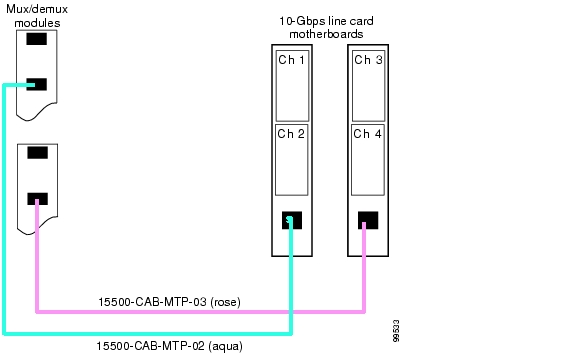
The MTP-to-MTP cables for the 10-Gbps line card motherboard are the 15500-CAB-MTP-02 (aqua) and the 15500-CAB-MTP-03 (rose) cables. Use the aqua colored cable to directly connect the lower channel 10-GE transponder modules to the mux/demux module. Use the rose colored cable to directly connect a higher channel 10-GE transponder module to the mux/demux module.
Figure 6-3 shows the aqua colored cable connecting a lower channel 10-GE transponder module (for example, channels 1/2, 5/6, 9/10, 13/14, 17/18, 21/22, 25/26, or 29/30) and the rose colored cable connecting a higher channel 10-GE transponder module (for example, channels 3/4, 7/8, 11/12, 15/16, 19/20, 23/24, 27/28, or 31/32).
Figure 6-3 MTP-to-MTP Cabling Example
Note
6.3.2 Direct Cabling Using MTP-to-2-MTP Cables
The MTP-to-2-MTP cable can be used to directly connect two 10-Gbps line card motherboards to a mux/demux module. Use this cable when you want to connect two 10-Gbps line card motherboards, containing four transponder modules supporting consecutive channels in the band, to a mux/demux module. Figure 6-5 shows an example of how you can connect two 10-Gbps line card motherboard to one mux/demux module with an MTP-to-2-MTP cable.
Figure 6-4 MTP-to-2-MTP Cabling Example
6.3.3 Cross Connect Drawer Cabling Using MTP-to-4-MU Cables
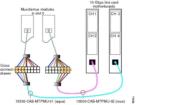
The MTP-to-4-MU cables for the 10-Gbps line card motherboard are the 15500-CAB-MTPMU-1 (aqua) and the 15500-CAB-MTPMU-2 (rose) cables. Figure 6-5 shows an example of how you can connect the 10-Gbps line card motherboard to the cross connect drawer.
Figure 6-5 Connecting 10-Gbps Line Card Motherboard to the Cross Connect Drawer
6.4 Troubleshooting 10-GE Transponder Module Interface Problems
This section contains troubleshooting procedures for 10-GE transponder module interface problems.
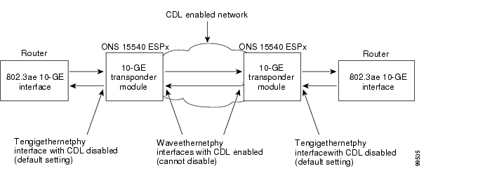
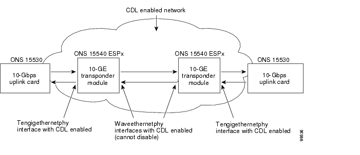
You can use the 10-GE transponder module on the Cisco ONS 15540 ESPx to connect to native IEEE 802.3ae 10-GE interfaces on the Catalyst 6500, the Catalyst 7600, or the Cisco Gigabit Switch Routers. You can also connect to a 1310-nm 10-Gbps uplink card on a Cisco ONS 15530. The CDL channel should be disabled on the tengigethernetphy interfaces on the 10-GE transponder module while connecting to the native IEEE 802.3ae interfaces and then enabled while connecting to the 10-Gbps uplink card (see Figure 6-6 and Figure 6-7).
Figure 6-6 Connecting to Native IEEE 802.3ae 10-GE Interfaces
Figure 6-7 Connecting to Cisco ONS 15530 Systems
Make sure the tengigethernetphy and waveethernetphy interfaces are not administratively shut down and that the laser is turned on. Use the no shutdown and no laser shutdown commands in interface configuration mode to enable the interface and turn on the laser before troubleshooting any problems.
6.4.1 Tengigethernetphy Interface Down and Shows Loss of Lock
Symptom A tengigethernetphy interface is down and signal quality status shows Loss of Lock.
Table 6-1 describes the potential causes of the symptom and the solutions.
6.4.2 Waveethernetphy Interface Down and Shows Loss of Lock
Symptom A waveethernetphy interface is down and signal quality status shows Loss of Lock.
Table 6-2 describes the potential causes of the symptom and the solutions.
6.4.3 Waveethernetphy Interface Down and Shows Loss of Sync
Symptom A waveethernetphy interface is down and signal quality status shows Loss of Sync.
Table 6-3 describes the potential causes of the symptom and the solutions.
6.4.4 Ethernetdcc Interface Down
Symptom The ethernetdcc interface is down and pings across the interface fail.
Table 6-4 describes the potential causes of the symptom and the solutions.
6.4.5 Tengigethernetphy Interface Shows CVRD Errors
Symptom A tengigethernetphy interface shows code violation and running disparity (CVRD) errors.
Note
Table 6-5 describes the potential causes of the symptom and the solutions.
6.4.6 Waveethernetphy Interface Shows CVRD Errors
Symptom A waveethernetphy interface shows CVRD errors.
Table 6-6 describes the potential cause of the symptom and the solution.
6.5 Troubleshooting 10-GE Transponder Module Problems Using Loopbacks
This section describes how to perform fault isolation on 10-GE transponder modules using the following types of loopbacks:
•
•
•
6.5.1 Physical Fiber Loopbacks
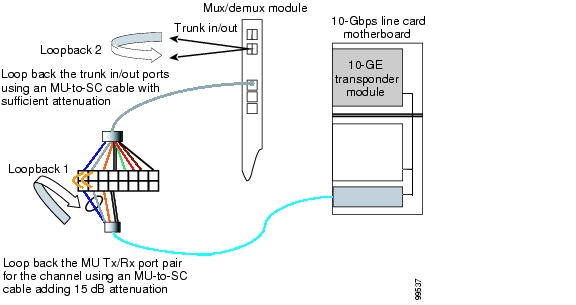
You can use physical fiber loopbacks at various places to check the connectivity and isolate a bad or dirty fiber. Using an SC-to-MU cable with a 15 dB attenuator, you can set up a loopback in the cross connect drawer for the MU pair of the channel being verified. This ensures that the connectivity between the 10-GE transponder module through the 10-Gbps line card motherboard onto the MTP-to-4-MU fiber is good (see Loopback 1 in the example in Figure 6-8). You can also loop back the multiplexed trunk fiber coming out of the trunk port in/out interfaces of the mux/demux module. This loopback verifies the connectivity from the 10-GE transponder module through the cross connect drawer and the mux/demux module (see Loopback 2 in the example in Figure 6-8).
Figure 6-8 Physical Fiber Loopback Examples
6.5.2 Client Signal Software Loopbacks
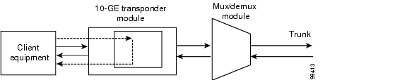
A client signal software loopback verifies the functioning between the client equipment and the 10-GE transponder module (see Figure 6-9).
Figure 6-9 Client Signal Loopback Example on a 10-GE Transponder Module
Procedure: Create a Client Signal Software Loopback
Step 1
Step 2
Step 3
6.5.3 Trunk Software Loopbacks
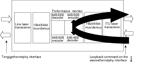
A trunk software loopback verifies the functioning of the 10-GE transponder module on the trunk side (see Figure 6-10). With this feature, you can verify the communication between two 10-GE transponder modules.
Figure 6-10 Trunk Side Loopback Example on a 10-GE Transponder Module
Procedure: Create a Trunk Software Loopback
Step 1
Step 2
Step 3
![]()
![]()
![]()
![]()
![]()
![]()
![]()
![]()
Posted: Thu Feb 16 04:33:33 PST 2006
All contents are Copyright © 1992--2006 Cisco Systems, Inc. All rights reserved.
Important Notices and Privacy Statement.