|
|

Table Of Contents
Cisco ONS 15540 ESPx Cleaning Procedures for Fiber Optic Connections
Cisco ONS 15540 ESPx Cleaning Kits
Inspecting the Cisco ONS 15540 ESPx Fiber Optic Connections
Cleaning Fiber Optic Connectors of the Cisco ONS 15540 ESPx
Cleaning the Fiber Optic Cables
Breakout Cable and Cross Connect Drawer Connectors
Obtaining Technical Assistance
Obtaining Additional Publications and Information
Cisco ONS 15540 ESPx Cleaning Procedures for Fiber Optic Connections
This document describes the processes and procedures for cleaning the fiber optic connectors and component interfaces of the Cisco ONS 15540 ESPx. It is intended for use by service personnel, field service technicians, and hardware installers. It is assumed that the user has knowledge of basic inspection techniques and cleaning processes for fiber optic connectors and component interfaces.
Warning
Only trained and qualified personnel should be allowed to install, replace, or service this equipment.
Warning
This document includes the following sections:
•
•
•
•
•
Introduction
Cleaning the fiber optic components of the Cisco ONS 15540 ESPx is important for maintaining the system. Any contamination in the fiber connection can cause failure of the component or failure of the entire system.
Microscopic dust particles can cause a variety of problems for optical connectors. A particle that partially or completely blocks the fiber core generates strong back reflections, which can cause instability in the laser system. Dust particles trapped between two fiber faces can scratch the glass surfaces. Even if a particle is only situated on the cladding or the ferrule, it can cause an air gap or misalignment between the fiber cores that can significantly degrade the optical signal.
•
•
By comparison, a typical human hair is 50 to 75 micrometers in diameter, as much as 8 times larger. So, even though dust may not be visible, it is still present in the air and can deposit onto the connector.
In addition to dust, other types of contamination must also be cleaned off the fiber. Such materials include:
•
•
•
These contaminants can be more difficult to remove than dust particles.
Caution
When cleaning fiber components, procedures must be followed precisely and carefully with the goal of eliminating any dust or contamination. A clean component connects properly; a dirty component may transfer contamination to the connector, or it may even damage the optical contacts.
Inspecting, cleaning, and re-inspecting are critical steps that must be done before making any fiber connection.
Inspection Equipment
It is important that every fiber connector be inspected with a microscope before a connection is made as many of the contaminants are too small to see with the naked eye. The fiber inspection scopes (not included in the Cisco ONS 15540 ESPx cleaning kit) described in this section are designed to magnify and display the critical portion of the ferrule where the connection is made.
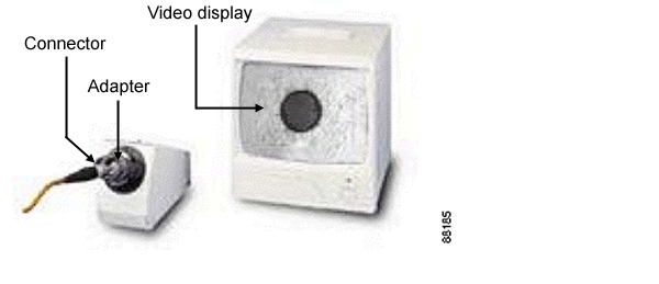
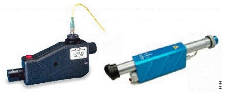
Video and Optical Fiberscopes
Fiberscopes are customized microscopes used to inspect optical fiber components. Figure 1, Figure 2, and Figure 3 show examples of the various fiber scopes available. The scope you chose should provide at least 200x magnification. Specific adapters are needed to properly inspect the ferrule faces of some connector types (such as the MPO, E2000, or MU connectors). In instances where multiple connector types need inspection, it may be more efficient to have a dedicated scope for each type of adapter.
Note
Figure 1 Video Fiberscope—Desktop
Figure 2 Optical Fiberscopes—Handheld
Bulkhead Fiberscope
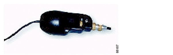
The bulkhead fiberscope is a handheld fiberscope used to inspect connectors in bulkhead ports. The scope should provide at least 200x magnification displayed on a video monitor. Specific adapters are needed to properly inspect the ferrule faces of some connector types (such as the MPO, E2000, or MU connectors). See Figure 3.
Figure 3 Bulkhead Fiberscope—Handheld
Laser Safety Glasses
Laser safety glasses can protect a person's eyes from laser light while handling fiber. They are intended to provide a level of protection across specific wavelengths. Be sure that the glasses are matched to the laser's wavelength. Laser safety glasses must meet federal and state regulations.
Cisco ONS 15540 ESPx Cleaning Kits
The Cisco ONS 15540 ESPx cleaning kit is available in two versions. The 2.5-Gbps transponder kit is used in systems with SM (single-mode), MM (multimode), and extended range transponder modules. Table 1 lists the contents of this kit. The 10-GE transponder kit is used in systems with the 10-GE transponder module. Table 2 lists the contents of this kit.
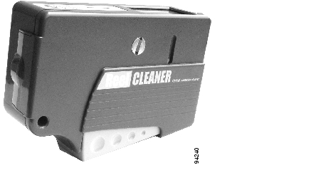
Cartridge Cleaners
Cartridge cleaners contain a roll of woven material packaged in a cassette (see Figure 4). When a lever is pressed, a shutter opens to provide access to a fresh span of cleaning material. The following cartridges are included in the cleaning kit:
•
Used to perform dry cleaning of MPO/MTP male connectors. It has two guide slots in the cleaning window. When the lever is pressed a shutter opens to provide a new section of the cleaning material.
•
Used to perform dry cleaning of 2.5-mm (SC, FC, and so on) and 1.25-mm (MU, LC, and so on) ferrule connectors and female multi-fiber connectors such as MT-RJ. When the lever is pressed, a shutter opens to provide a new section of the cleaning material.
Note
Figure 4 Cartridge Cleaner
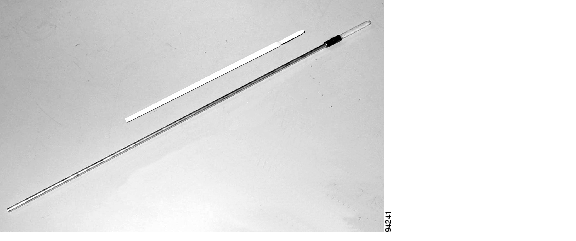
Lint-Free Swabs
Swabs have a fabric tip at the end of a long stick. Lint-free swabs should be stored in a clean container to avoid contamination of the tip. Be sure to use a swab sized properly for the ferrule type (1.25 mm or 2.5 mm). See Figure 5.
Caution
Figure 5 1.25-mm and 2.5-mm Lint-Free Swabs
Inspecting the Cisco ONS 15540 ESPx Fiber Optic Connections
Inspecting the fiber optic connectors for dust particles or other contaminants before bringing the card or module online can help to prevent system failures. Always work carefully around lasers and fiber optic connections. Keep the following information in mind.
•
•
•
•
•
•
•
•
•
•
•
•
•
•
•
Warning
Cleaning Fiber Optic Connectors of the Cisco ONS 15540 ESPx
The Cisco ONS 15540 ESPx cleaning kits provide the necessary tools and accessories to clean the various fiber optic connectors used on the system. This section describes the use of the cleaning kit with the various cards and modules installed in the Cisco ONS ESPx, and it includes the following topics:
•
•
We recommend inspecting the optical connectors both before and after cleaning.
Mux/Demux Modules
To clean the optical connections of the mux/demux modules, follow these steps:
Caution
Step 1
Step 2
Step 3
Figure 6 Cleaning Adapter for MPO/MTP Connectors
Figure 7 Cleaning Adapter for MU Connectors
Step 4
Note
Step 5
Step 6
Step 7
Protection Switch Modules
To clean the optical connections of the PSMs (protection switch modules), follow these steps:
Caution
Step 1
Step 2
Step 3
Step 4
Note
Step 5
Step 6
Step 7
Transponder Modules
This section describes the procedures for cleaning the fiber optic connections of the transponder modules and includes these topics:
•
2.5-Gbps Transponder Modules
Cleaning the 2.5-Gbps transponder module optical connections includes the optical connectors on the backplane, the optical connectors on the transponder module (front and back), and the fiber optic cable connectors. The following sections describe this process:
•
•
•
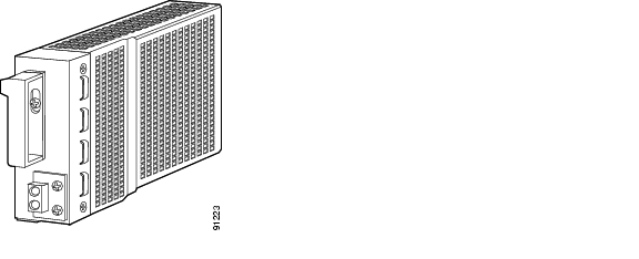
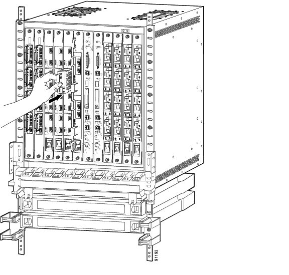
Cleaning the 2.5-Gbps Line Card Backplane Connectors
To clean the 2.5-Gbps line card backplane connectors, follow these steps:
Caution
Step 1
Step 2
Step 3
Step 4
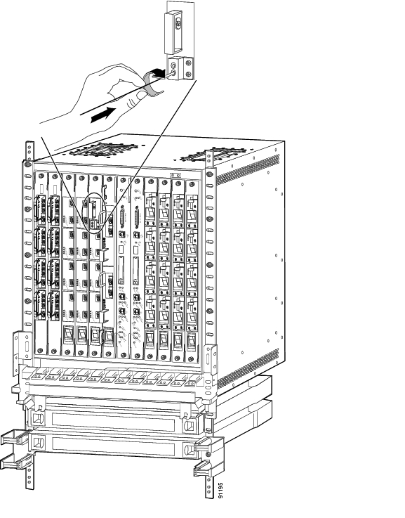
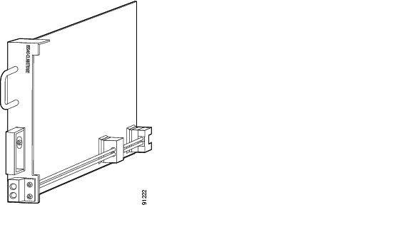
Figure 8 2.5-Gbps Transponder Cleaning Module
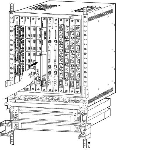
Figure 9 Installing the 2.5-Gbps Transponder Cleaning Module
Step 5
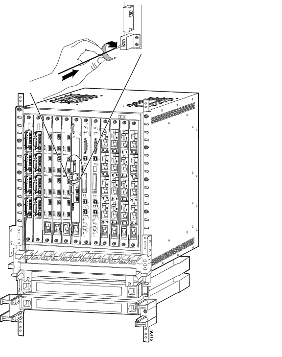
Figure 10 Cleaning the Backplane Connections of the 2.5-Gbps Line Card Motherboard
Step 6
Step 7
Step 8
Step 9
Step 10
Note
Step 11
Step 12
Step 13
Cleaning the 2.5-Gbps Transponder Module Faceplate Connectors
To clean the fiber optic connectors on the front of the 2.5-Gbps transponder module, follow these steps:
Caution
Step 1
Step 2
Caution
Step 3
Note
Step 4
Step 5
Step 6
Cleaning the 2.5-Gbps Line Card Motherboard Faceplate Connectors
To clean the MPO/MTP ports on the bottom front of the 2.5-Gbps line card motherboard, follow these steps:
Caution
Step 1
Step 2
Step 3
Step 4
Note
Step 5
Step 6
Step 7
10-GE Transponder Modules
Cleaning the10-GE transponder module optical connections includes the optical connectors on the backplane, the optical connectors on the transponder module (front and back), and the fiber optic cable connectors. The following sections describe this process:
•
•
•
Cleaning the 10-GE Line Card Backplane Connectors
To clean the 10-GE line card backplane connections, follow these steps:
Caution
Step 1
Step 2
Step 3
Step 4
Figure 11 10-GE Transponder Cleaning Module
Figure 12 Installing the 10-GE Transponder Cleaning Module
Step 5
Step 6
Step 7
Step 8
Step 9
Step 10
Figure 13 Cleaning the Backplane Connections of the 10-GE Line Card Motherboard
Note
Step 11
Step 12
Step 13
Cleaning the 10-GE Transponder Module Faceplate Connectors
To clean the SC connectors on the front of the 10-GE transponder module, follow these steps:
Caution
Step 1
Step 2
Step 3
Note
Step 4
Step 5
Step 6
Cleaning the 10-GE Line Card Motherboard Faceplate Connectors
To clean the MPO/MTP ports on the bottom front of the10-GE line card motherboard, follow these steps:
Caution
Step 1
Step 2
Step 3
Step 4
Note
Step 5
Step 6
Step 7
Cleaning the Fiber Optic Cables
To clean the fiber optic cables, follow these steps:
Caution
Step 1
Step 2
Step 3
Step 4
Step 5
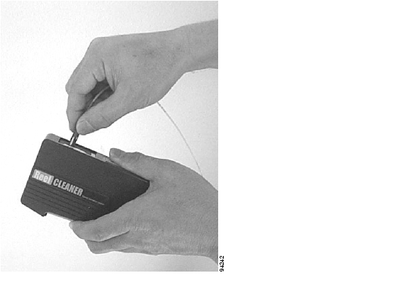
Figure 14 Using the OPTIPOP Cleaner
Step 6
Step 7
Caution
Step 8
Note
Step 9
Step 10
Step 11
Breakout Cable and Cross Connect Drawer Connectors
The cable connectors in the cross connect drawer and the breakout cable connectors are MU.
Cleaning the Breakout Cable Connectors
To clean the breakout cable connectors, follow these steps:
Caution
Step 1
Step 2
Step 3
Step 4
Step 5
Step 6
Step 7
Step 8
Cleaning the Cross Connect Drawer Connectors
To clean the cross connect drawer connectors, follow these steps:
Step 1
Step 2
Step 3
Note
Step 4
Step 5
Step 6
Step 7
Related Documentation
Refer to the following documents for more information about the Cisco ONS 15540 ESPx:
•
•
•
•
•
•
•
•
•
•
•
•
•
Obtaining Documentation
Cisco documentation and additional literature are available on Cisco.com. Cisco also provides several ways to obtain technical assistance and other technical resources. These sections explain how to obtain technical information from Cisco Systems.
Cisco.com
You can access the most current Cisco documentation on the World Wide Web at this URL:
http://www.cisco.com/univercd/home/home.htm
You can access the Cisco website at this URL:
International Cisco websites can be accessed from this URL:
http://www.cisco.com/public/countries_languages.shtml
Ordering Documentation
You can find instructions for ordering documentation at this URL:
http://www.cisco.com/univercd/cc/td/doc/es_inpck/pdi.htm
You can order Cisco documentation in these ways:
•
http://www.cisco.com/en/US/partner/ordering/index.shtml
•
Documentation Feedback
You can submit e-mail comments about technical documentation to bug-doc@cisco.com.
You can submit comments by using the response card (if present) behind the front cover of your document or by writing to the following address:
Cisco Systems
Attn: Customer Document Ordering
170 West Tasman Drive
San Jose, CA 95134-9883We appreciate your comments.
Obtaining Technical Assistance
For all customers, partners, resellers, and distributors who hold valid Cisco service contracts, the Cisco Technical Assistance Center (TAC) provides 24-hour-a-day, award-winning technical support services, online and over the phone. Cisco.com features the Cisco TAC website as an online starting point for technical assistance. If you do not hold a valid Cisco service contract, please contact your reseller.
Cisco TAC Website
The Cisco TAC website provides online documents and tools for troubleshooting and resolving technical issues with Cisco products and technologies. The Cisco TAC website is available 24 hours a day, 365 days a year. The Cisco TAC website is located at this URL:
Accessing all the tools on the Cisco TAC website requires a Cisco.com user ID and password. If you have a valid service contract but do not have a login ID or password, register at this URL:
http://tools.cisco.com/RPF/register/register.do
Opening a TAC Case
Using the online TAC Case Open Tool is the fastest way to open P3 and P4 cases. (P3 and P4 cases are those in which your network is minimally impaired or for which you require product information.) After you describe your situation, the TAC Case Open Tool automatically recommends resources for an immediate solution. If your issue is not resolved using the recommended resources, your case will be assigned to a Cisco TAC engineer. The online TAC Case Open Tool is located at this URL:
http://www.cisco.com/tac/caseopen
For P1 or P2 cases (P1 and P2 cases are those in which your production network is down or severely degraded) or if you do not have Internet access, contact Cisco TAC by telephone. Cisco TAC engineers are assigned immediately to P1 and P2 cases to help keep your business operations running smoothly.
To open a case by telephone, use one of the following numbers:
Asia-Pacific: +61 2 8446 7411 (Australia: 1 800 805 227)
EMEA: +32 2 704 55 55
USA: 1 800 553-2447For a complete listing of Cisco TAC contacts, go to this URL:
http://www.cisco.com/warp/public/687/Directory/DirTAC.shtml
TAC Case Priority Definitions
To ensure that all cases are reported in a standard format, Cisco has established case priority definitions.
Priority 1 (P1)—Your network is "down" or there is a critical impact to your business operations. You and Cisco will commit all necessary resources around the clock to resolve the situation.
Priority 2 (P2)—Operation of an existing network is severely degraded, or significant aspects of your business operation are negatively affected by inadequate performance of Cisco products. You and Cisco will commit full-time resources during normal business hours to resolve the situation.
Priority 3 (P3)—Operational performance of your network is impaired, but most business operations remain functional. You and Cisco will commit resources during normal business hours to restore service to satisfactory levels.
Priority 4 (P4)—You require information or assistance with Cisco product capabilities, installation, or configuration. There is little or no effect on your business operations.
Obtaining Additional Publications and Information
Information about Cisco products, technologies, and network solutions is available from various online and printed sources.
•
http://www.cisco.com/go/marketplace/
•
http://cisco.com/univercd/cc/td/doc/pcat/
•
•
•
http://www.cisco.com/go/iqmagazine
•
•
http://www.cisco.com/en/US/learning/index.html
This document is to be used in conjunction with the documents listed in the "Related Documentation" section.
CCIP, CCSP, the Cisco Arrow logo, the Cisco Powered Network mark, Cisco Unity, Follow Me Browsing, FormShare, and StackWise are trademarks of Cisco Systems, Inc.; Changing the Way We Work, Live, Play, and Learn, and iQuick Study are service marks of Cisco Systems, Inc.; and Aironet, ASIST, BPX, Catalyst, CCDA, CCDP, CCIE, CCNA, CCNP, Cisco, the Cisco Certified Internetwork Expert logo, Cisco IOS, the Cisco IOS logo, Cisco Press, Cisco Systems, Cisco Systems Capital, the Cisco Systems logo, Empowering the Internet Generation, Enterprise/Solver, EtherChannel, EtherSwitch, Fast Step, GigaStack, Internet Quotient, IOS, IP/TV, iQ Expertise, the iQ logo, iQ Net Readiness Scorecard, LightStream, MGX, MICA, the Networkers logo, Networking Academy, Network Registrar, Packet, PIX, Post-Routing, Pre-Routing, RateMUX, Registrar, ScriptShare, SlideCast, SMARTnet, StrataView Plus, Stratm, SwitchProbe, TeleRouter, The Fastest Way to Increase Your Internet Quotient, TransPath, and VCO are registered trademarks of Cisco Systems, Inc. and/or its affiliates in the U.S. and certain other countries.
All other trademarks mentioned in this document or Web site are the property of their respective owners. The use of the word partner does not imply a partnership relationship between Cisco and any other company. (0304R)
Cisco ONS 15540 ESPx Cleaning Procedures for Fiber Optic Connections
Copyright © 2003 Cisco Systems, Inc. All rights reserved.
![]()
![]()
![]()
![]()
![]()
![]()
![]()
![]()
Posted: Thu Jan 13 12:34:10 PST 2005
All contents are Copyright © 1992--2005 Cisco Systems, Inc. All rights reserved.
Important Notices and Privacy Statement.