|
|

Table Of Contents
Configuring 2.5-Gbps Transponder Module Interfaces and Patch Connections
Configuring Protocol Encapsulation or Clock Rate
Displaying Protocol Encapsulation or Clock Rate Configuration
Configuring Protocol Monitoring
Displaying Protocol Monitoring Configuration
Displaying Alarm Threshold Configuration
Configuring Forward Laser Control
Configuring Laser Safety Control
Configuring Transponder Channel Frequency
Configuring Optical Power Thresholds
Displaying Protocol Monitoring Configuration
Configuring 2.5-Gbps Transponder Module Interfaces and Patch Connections
This chapter describes how to configure interfaces and patch connections on the Cisco ONS 15540 ESPx. This chapter includes the following sections:
•
Configuring Protocol Encapsulation or Clock Rate
•
•
•
•
Note
To configure transparent interfaces on the Cisco ONS 15540 ESPx, perform the following steps:
Step 1
Step 2
Step 3
Step 4
To configure wave interfaces on the Cisco ONS 15540 ESPx, perform the following steps:
Step 1
Step 2
To configure patch connections on the Cisco ONS 15540 ESPx, perform the following steps:
Step 1
Step 2
Configuring Protocol Encapsulation or Clock Rate
A transparent interface does not terminate the protocol of the signal it receives but it does convert it from an optical signal to an electrical signal and back to an optical signal. Therefore, you must configure the signal transmission rate by specifying either the protocol encapsulation or the clock rate.
To configure the protocol encapsulation or the clock rate for a transparent interface, perform the following steps, beginning in global configuration mode:
Step 1
Switch(config)# interface transparent slot/subcard/0
Switch(config-if)#
Selects the interface to configure and enters interface configuration mode.
Step 2
Switch(config-if)# encapsulation {fastethernet | fddi | gigabitethernet | escon}
orSwitch(config-if)# encapsulation sysplex clo
orSwitch(config-if)# encapsulation sysplex etr
orSwitch(config-if)# encapsulation sysplex isc {compatibility | peer}
orSwitch(config-if)# encapsulation ficon {1g | 2g}
orSwitch(config-if)# encapsulation sonet {oc3 | oc12 | oc48}
orSwitch(config-if)# encapsulation sdh {stm-1 | stm-4 | stm-16}
orSwitch(config-if)# encapsulation fibrechannel {1g | 2g} [ofc {enable | disable}]
orSwitch(config-if)# clock rate value
Specifies Fast Ethernet, FDDI, Gigabit Ethernet, or ESCON. OFC1 is disabled.
Specifies Sysplex CLO2 . OFC is disabled. Forward laser control is enabled on both the transparent and wave interfaces. OFC is disabled.
Specifies Sysplex ETR3 . OFC is disabled.
Specifies ISC4 compatibility mode (1 Gbps) or peer mode (2 Gbps). OFC is enabled for compatibility mode and disabled for peer mode.
Specifies FICON as the signal protocol and 1 Gbps or 2 Gbps as the transmission rate. OFC is disabled.
Specifies SONET as the signal protocol and OC-3, OC-12, or OC-48 as the transmission rate. OFC is disabled.
Specifies SDH as the signal protocol and STM-1, STM-4, or STM-16 as the transmission rate. OFC is disabled.
Specifies Fibre Channel as the signal protocol and 1 Gbps or 2 Gbps as the transmission rate. Enables or disables OFC. OFC is disabled by default.
Specifies the signal transmission clock rate without an associated protocol. OFC is disabled.
Note
1 For information about OFC, see the "About Laser Shutdown" section.
2 CLO = control link oscillator
3 ETR = external timer reference
4 ISC = Intersystem Channel Links
Note
Caution
Note
Table 4-1 lists the clock rates for well-known protocols supported by the 2.5-Gbps transponder module:
1 DV = digital video
2 ADI = Asynchronous Digital Interface
Note
Note
The following ranges are not supported by the SM transponder module hardware and the MM transponder module hardware:
•
•
For clock rate values outside of these unsupported ranges and not listed in Table 4-1, contact your SE (systems engineer) at Cisco Systems.
Note
Caution
For information on SFP optics specifications, refer to the Cisco ONS 15540 ESPx Hardware Installation Guide.
Note
Examples
The following example shows how to configure GE (Gigabit Ethernet) encapsulation on a transparent interface:
Switch(config)# interface transparent 8/0/0Switch(config-if)# encapsulation gigabitethernetThe following example shows how to configure a clock rate on a transparent interface:
Switch(config)# interface transparent 10/1/0Switch(config-if)# clock rate 1065
Note
Displaying Protocol Encapsulation or Clock Rate Configuration
To display the protocol encapsulation configuration of a transparent interface, use the following EXEC command:
show interfaces transparent slot/subcard/0
Displays the transparent interface configuration.
Examples
The following example shows how to display the protocol encapsulation configuration of a transparent interface:
Switch# show interfaces transparent 8/0/0Transparent11/3/0 is up, line protocol is upEncapsulation: GigabitEthernetSignal monitoring: offTime of last "monitor" state change neverTime of last "encapsulation" change 00:00:03Forward laser control: OffConfigured threshold Group: NoneLoopback not setLast clearing of "show interface" counters 00:00:03Hardware is transparentThe following example shows how to display the clock rate configuration of a transparent interface:
Switch# show interfaces transparent 10/1/0Transparent11/3/0 is up, line protocol is upEncapsulation: UnknownClock rate: 1000000 KHzSignal monitoring: offTime of last "monitor" state change neverTime of last "encapsulation" change neverForward laser control: OffConfigured threshold Group: NoneLoopback not setLast clearing of "show interface" counters neverHardware is transparentAbout Protocol Monitoring
Transparent interfaces on the Cisco ONS 15540 ESPx can be configured to monitor protocol and signal performance. When monitoring is enabled, the system maintains statistics that are used to determine the quality of the signal.
The following protocols can be monitored:
•
•
•
•
•
•
•
Note
For Gigabit Ethernet, Fibre Channel, and FICON, the Cisco ONS 15540 ESPx monitors the code violation and running disparity error count.
For SONET errors, the Cisco ONS 15540 ESPx monitors the SONET section overhead only, not the SONET line overhead. Specifically, the Cisco ONS 15540 ESPx monitors the B1 byte and the framing bytes. The system can detect the following defect conditions:
•
•
•
•
For SONET performance, the system monitors the B1 byte, which is used to compute the four SONET section layer performance monitor parameters:
•
•
•
•
Configuring Protocol Monitoring
To configure protocol monitoring on a transparent interface, and its corresponding wave interface, perform the following steps, beginning in global configuration mode:
Examples
The following example shows how to enable protocol monitoring on a transparent interface:
Switch(config)# interface transparent 10/0/0Switch(config-if)# monitor enableThe following example shows how to disable protocol monitoring on a transparent interface:
Switch(config)# interface transparent 10/0/0Switch(config-if)# no monitor enableDisplaying Protocol Monitoring Configuration
To display the protocol monitoring configuration of a transparent interface, use the following EXEC command:
show interfaces {transparent slot/subcard/0 | wave slot/subcard}
Displays the transparent interface configuration.
Examples
The following example shows how to display the protocol monitoring configuration of a transparent interface:
Switch# show interfaces transparent 10/0/0Transparent10/0/0 is up, line protocol is upSignal quality: Signal degrade threshold exceededEncapsulation: Sonet Rate: oc3Signal monitoring: on
Forward laser control: OffConfigured threshold Group: NoneLoopback not setLast clearing of "show interface" counters neverHardware is transparentThe following example shows how to display the protocol monitoring configuration of a wave interface:
Switch# show interfaces wave 10/0Wave10/0 is up, line protocol is upChannel: 25 Frequency: 195.1 Thz Wavelength: 1536.61 nmSplitter Protected: NoReceiver power level: -7.0 dBmLaser safety control: OffForward laser control: OffOsc physical port: NoWavelength used for inband management: NoConfigured threshold Group: NoneSection code violation error count(bip1): 929326Number of errored seconds(es): 30Number of severely errored seconds(ses): 30Number of severely errored framing seconds(sefs): 0Loopback not setLast clearing of "show interface" counters neverHardware is data_only_portAbout Alarm Thresholds
You can configure thresholds on transparent and wave interfaces that issue alarm messages to the system if the thresholds are exceeded. The threshold values are applied to both transparent and wave interfaces on a transponder module when protocol monitoring is enabled on the transparent interface.
The rate is based on the protocol encapsulation or the clock rate for the interface. Every second, the monitoring facility updates the counters that correspond to the alarm thresholds. When the signal degrades, or fails entirely, the system issues alarms to the console. These alarms can help isolate failures in the system and in the network.
You can configure more than one threshold list on an interface. The threshold lists cannot have overlapping counters so that only one counter is set for the interface. Also, the threshold list name cannot begin with the text string "default" because the it is reserved for use by the system.
Configuring Alarm Thresholds
To configure alarm thresholds on transparent interfaces, perform the following steps, beginning in global configuration mode:
Step 1
Switch(config)# threshold-list name
Switch(config-t-list)#
Creates or selects the threshold list to configure and enters threshold list configuration mode.
Note
Step 2
Switch(config-t-list)# notification-throttle timer seconds
Configures the SNMP notification timer. The default value is 5 seconds. (Optional)
Step 3
Switch(config-t-list)# threshold name {cvrd | cdl hec | crc | sonet-sdh section cv | tx-crc} {failure | degrade} [index value]
Switch(config-threshold)#
Specifies a threshold type to modify and enters threshold configuration mode.
Step 4
Switch(config-threshold)# value rate value
Specifies the threshold rate value. This value is the negative power of 10 (10-n).
Step 5
Switch(config-threshold)# description text
Specifies a description of the threshold. The default value is the null string. (Optional)
Step 6
Switch(config-threshold)# aps trigger
Enables APS switchover when this threshold is crossed. (Optional)
Note
Step 7
Switch(config-threshold)# exit
Switch(config-t-list)#
Returns to threshold list configuration mode.
Repeat Step 3 through Step 7 to configure more thresholds in the threshold list.
Step 8
Switch(config-t-list)# exit
Switch(config)#
Returns to global configuration mode.
Step 9
Switch(config)# interface {transparent slot/subcard/0 | wave slot/subcard}
Switch(config-if)#
Selects the transparent or wave interface to configure and enters interface configuration mode.
Step 10
Switch(config-if)# threshold-group name
Configures the threshold list on the interface.
Note
Note
Table 4-2 lists the threshold error rates in errors per second for each of the protocol encapsulations.
Table 4-2 Thresholds for Monitored Protocols (Errors Per Second)
3
31,7533
32,0003
32,0003
1,244,390
199,102
1,057,731
1,057,731
1,057,731
4
12,318
27,421
31,9873
124,944
19,991
106,202
106,202
106,202
5
1518
5654
17,296
12,499
2000
10,625
10,625
10,625
6
155
616
2394
1250
200
1062
1062
1062
7
15.5
62
248
125
20
106
106
106
8
1.55
6.2
24.8
12.5
2
10.6
10.6
10.6
9
0.155
0.62
2.48
1.25
0.2
1.06
1.06
1.06
1 One Gbps rate only.
2 Compatibility mode only.
3 Rate is limited by the hardware.
Examples
The following example shows how to create an alarm threshold list and configure that list on a transparent interface:
Switch# configure terminalSwitch(config)# threshold-list sonet-countersSwitch(config-t-list)# threshold name sonet-sdh section cv degradeSwitch(config-threshold)# value rate 9Switch(config-threshold)# exitSwitch(config-t-list)# threshold name sonet-sdh section cv failureSwitch(config-threshold)# value rate 7Switch(config-threshold)# exitSwitch(config-t-list)# exitSwitch(config)# interface transparent 10/0/0Switch(config-if)# threshold-group sonet-countersThe following example shows how to create an alarm threshold list with the APS switchover trigger and configure that list on a pair of associated transparent interfaces:
Switch(config)# threshold-list sonet-alarmsSwitch(config-t-list)# threshold name sonet-sdh section cv failureSwitch(config-threshold)# value rate 6Switch(config-threshold)# aps triggerSwitch(config-threshold)# exitSwitch(config-t-list)# exitSwitch(config)# redundancySwitch(config-red)# associate group sonet-channelSwitch(config-red-aps)# aps working transparent 3/0/0Switch(config-red-aps)# aps protection transparent 3/0/0Switch(config-red-aps)# aps y-cableSwitch(config-red-aps)# aps revertiveSwitch(config-red-aps)# enableSwitch(config-red-aps)# exitSwitch(config-red)# exitSwitch(config)# interface transparent 3/0/0Switch(config-if)# encap sonet oc3Switch(config-if)# monitor enableSwitch(config-if)# threshold-group sonet-alarmsSwitch(config-if)# exitSwitch(config)# interface transparent 5/0/0Switch(config-if)# encap sonet oc3Switch(config-if)# monitor enableSwitch(config-if)# threshold-group sonet-alarmsDisplaying Alarm Threshold Configuration
To display the configuration of a threshold list and the threshold group for a transparent or wave interface, use the following EXEC commands:
Examples
The following example shows how to display the configuration of a threshold group:
Switch# show threshold-list sonet-countersThreshold List Name: sonet-countersNotification throttle timer : 5 (in secs)Threshold name : sonet-sdh section cv Severity : DegradeValue : 10e-9APS Trigger : Not setDescription : SONET BIP1 counterThreshold name : sonet-sdh section cv Severity : FailureValue : 10e-6APS Trigger : SetDescription : SONET BIP1 counterThe following example shows how to display the threshold group information for an interface:
Switch# show interfaces transparent 3/1/0Transparent3/1/0 is up, line protocol is upEncapsulation: Sonet Rate: oc3Signal monitoring: onForward laser control: OffConfigured threshold Group: sonet-countersThreshold monitored for: sonet-sdh section cvSF set value: 10e-8 (155 in 100 secs)SD set value: 10e-9 (155 in 1000 secs)Section code violation error count(bip1): 3713975925Number of errored seconds(es): 57203Number of severely errored seconds(ses): 57203Number of severely errored framing seconds(sefs): 0Number of times SEF alarm raised: 0Number of times SF threshold exceeded: 0Number of times SD threshold exceeded: 378Loopback not setLast clearing of "show interface" counters neverHardware is transparentAbout Laser Shutdown
To avoid operator injury or transmission of unreliable data, or to provide quick path switchover, the Cisco ONS 15540 ESPx supports mechanisms to automatically shut down transponder module lasers. The three types of laser shutdown mechanisms are:
•
•
•
About Forward Laser Control
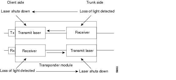
When loss of light occurs on the receive signal of a transparent or wave interface, the corresponding transmitting laser on the other side of the transponder module continues to function and might send unreliable information to the client. Forward laser control provides a means to quickly shut down a transmitting laser when such a receive signal failure occurs (see Figure 4-1). The receive signal loss of light can result from a failure in the client equipment, a receiver failure in the transponder module, or a laser shutdown on another node in the network.
This feature is convenient for configurations, such as Sysplex, where signal protection is performed in the client hardware and a quick laser shutdown causes a quick path switchover.
Figure 4-1 Forward Laser Control Overview
About OFC
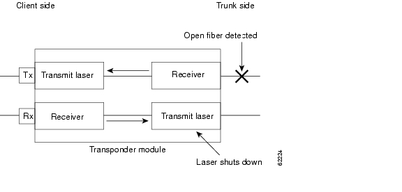
The Cisco ONS 15540 ESPx allows you to enable the OFC safety protocol on the client side interfaces. When the system detects an "open fiber," the laser that transmits to the client equipment shuts down. An open fiber condition occurs when the connectors to the client equipment are detached from the transponder ports or when the fiber is cut (see Figure 4-2).
Figure 4-2 OFC Overview
The OFC safety protocol conforms to the Fibre Channel standard. It applies only to the Fibre Channel and ISC compatibility mode encapsulations. The Cisco ONS 15540 ESPx interoperates with OFC-standard-compliant client equipment.
Caution
Use the encapsulation command, described in the "Configuring Protocol Encapsulation or Clock Rate" section to configure OFC on a transparent interface.
About Laser Safety Control
The Cisco ONS 15540 ESPx allows you to enable laser safety control on the trunk side interfaces of the transponder modules. Much like OFC, the laser safety control protocol shuts down the transponder module laser transmitting to the trunk when a fiber cut occurs or when the trunk fiber is detached from the shelf (see Figure 4-3).
Figure 4-3 Laser Safety Control Overview
Laser safety control uses the same protocol state machine as OFC, but not the same timing. Laser safety control uses the pulse interval and pulse duration timers compliant with the ALS (automatic laser shutdown) standard (ITU-T G.664).
Use laser safety control with line card protected and unprotected configurations only. Enable laser safety control on all wave interfaces, including the OSC.
Caution
Configuring Laser Shutdown
This sections describes how to configure forward laser control and laser safety control on the Cisco ONS 15540 ESPx transponder module interfaces.
Note
Configuring Forward Laser Control
To configure forward laser control on a transponder module transparent and wave interfaces, perform the following steps, beginning in global configuration mode:
Caution
Examples
The following example shows how to configure forward laser control for the transparent and wave interfaces on a transponder module:
Switch(config)# interface transparent 5/1/0Switch(config-if)# laser control forward enableSwitch(config-if)# exitSwitch(config)# interface wave 5/1Switch(config-if)# laser control forward enableDisplaying Forward Laser Control Configuration
To display the forward laser control configuration of a transparent or wave interface, use the following EXEC command:
show interfaces {transparent slot/subcard/port | wave slot/subcard}
Displays interface information.
Example
The following example shows how to display the forward laser control configuration for an interface:
Switch# show interfaces transparent 10/0/0Transparent10/0/0 is up, line protocol is upEncapsulation: Sonet Rate: oc3Signal monitoring: offTime of last "monitor" state change neverTime of last "encapsulation" change 10:18:20Forward laser control: OnConfigured threshold Group: NoneLoopback not setLast clearing of "show interface" counters 10:18:20Hardware is transparentConfiguring Laser Safety Control
To configure laser safety control on a wave interface, perform the following steps, beginning in global configuration mode:
Note
Caution
Example
The following example shows how to configure laser safety control on a wave interface:
Switch(config)# interface wave 8/0Switch(config-if)# laser control safety enableDisplaying Laser Safety Control Configuration
To display the laser safety control configuration of a wave interface, use the following EXEC command:
Example
The following example shows how to display the laser safety control configuration for an interface:
Switch# show interfaces wave 3/1launch2#show interfaces wave 10/0Wave10/0 is up, line protocol is upChannel: 25 Frequency: 195.1 Thz Wavelength: 1536.61 nmSplitter Protected: YesReceiver power level: -10.0 dBmLaser safety control: OnForward laser control: OffOsc physical port: NoWavelength used for inband management: NoConfigured threshold Group: NoneLoopback not setLast clearing of "show interface" counters neverHardware is data_only_portConfiguring Transponder Channel Frequency
The transponders supported by the Cisco ONS 15540 ESPx transmits at one of two channel frequencies. You can select the channel frequency using the CLI (command-line interface). To change the channel frequency transmitted by the transponder module laser, perform the following steps, beginning in global configuration mode:
Note
Example
The following example shows how to change the transponder channel frequency:
Switch(config)# interface wave 10/0Switch(config-if)# laser frequency 192300Displaying Transponder Channel Frequency
To display the channel frequency configuration, use the following EXEC command:
Example
The following example shows how to verify the transponder channel frequency:
Switch# show interface wave 10/0Wave10/0 is down, line protocol is downChannel: 30 Frequency: 195.7 Thz Wavelength: 1531.90 nmActive Wavepatch : Wavepatch10/0/0Splitter Protected: NoSignal quality: Loss of lightReceiver power level:Forward laser control: OffLaser safety control: OffOsc physical port: NoWavelength used for inband management: NoConfigured threshold Group: NoneLoopback not setLast clearing of "show interface" counters neverHardware is data_only_portConfiguring Optical Power Thresholds
Optical power thresholds provide a means of monitoring the signal power from the ITU laser. Four types of thresholds are provided:
•
•
•
•
When a threshold is crossed, the system sends a message to the console.
Note
To configure optical power thresholds for wavepatch interfaces on a transponder module, perform the following steps, beginning in global configuration mode:
Examples
The following example shows how to configure optical power thresholds for wavepatch interfaces on a transponder line card:
Switch(config)# interface wavepatch 4/0/0Switch(config-if)# optical threshold power receive high alarm -70Displaying Optical Power Threshold Configuration
To display the optical power thresholds for a wavepatch interface, use the following EXEC command:
Example
The following example shows how to display the optical power threshold configuration for an interface:
Switch# show interfaces wavepatch 4/0/0Wavepatch4/0/0 is up, line protocol is upReceiver power level: -23.91 dBmOptical threshold monitored for : Receive Power (in dBm)Low alarm value = -28.0 (default)Low Alarm Severity = majorLow warning value = -24.0 (default)Low Warning Severity = not alarmedHigh alarm value = -8.0 (default)High Alarm Severity = majorHigh warning value = -10.0 (default)High Warning Severity = not alarmedHardware is passive_portAbout Patch Connections
Because the mux/demux modules are passive devices, the Cisco ONS 15540 ESPx does not detect its optical patch connection configuration. For system management purposes, you must also configure the patch connection configuration using the CLI.
Note
Table 4-3 describes the types of patch connections on the Cisco ONS 15540 ESPx.
For more information on patch connection rules, refer to the
Cisco ONS 15540 ESPx Planning Guide .Configuring Patch Connections
To configure patch connections between mux/demux modules within the same shelf, use the following global configuration commands:
patch thru slot/subcard1 wdm slot/subcard2
or
patch wdm slot/subcard1 thru slot/subcard2
Configures the patch connection between two add/drop mux/demux modules in the same chassis slot.
patch thru slot1/subcard1 thru slot2/subcard2
Configures the patch connection between two add/drop mux/demux modules in different chassis slots.
patch filterband slot1/subcard1/port1 filtergroup slot2/subcard2/port2
or
patch filtergroup slot1/subcard1/port1 filterband slot2/subcard2/port2
Configures the patch connection between a terminal mux/demux module supporting channels 1 through 16 and a terminal mux/demux module supporting channels 17 through 32 in the same chassis slot or in different chassis slots.
patch wave slot oscfilter slot/subcard
or
patch oscfilter slot/subcard wave slot
Configures the patch connection between an OSC wave interface on a mux/demux motherboard and an OSC oscfilter interface on a mux/demux module in the same chassis slot.
Note
patch wavepatch slot1/subcard1/port1 filter slot2/subcard2/port2
or
patch filter slot1/subcard1/port1 wavepatch slot2/subcard2/port2
Configures the patch connection between a wavepatch interface on the line card motherboard and a filter interface on a mux/demux module or a mux/demux motherboard (Cisco ONS 15540 ESPx only).
Note
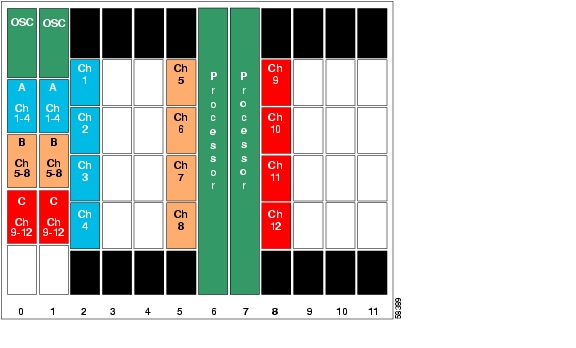
Figure 4-4 shows an example of a shelf configured with splitter protection for 12 channels.
Figure 4-4 Example Splitter Protected Shelf Configuration
The line card motherboards directly connect to the optical filter connectors on the mux/demux modules.
Example
The following example shows how to configure the patch connections between OSC interfaces, between mux/demux modules, and between the line card motherboards and the mux/demux modules in Figure 4-4:
Switch# configure terminalSwitch(config)# patch thru 0/0 wdm 0/1Switch(config)# patch thru 0/1 wdm 0/2Switch(config)# patch thru 0/2 thru 1/0Switch(config)# patch thru 1/1 wdm 1/0Switch(config)# patch thru 1/2 wdm 1/1Switch(config)# patch wave 0 oscfilter 0/0Switch(config)# patch wave 1 oscfilter 1/2Switch(config)# patch wavepatch 2/0/0 filter 0/0/0Switch(config)# patch wavepatch 2/1/0 filter 0/0/1Switch(config)# patch wavepatch 2/2/0 filter 0/0/2Switch(config)# patch wavepatch 2/3/0 filter 0/0/3Switch(config)# patch wavepatch 2/0/1 filter 1/0/0Switch(config)# patch wavepatch 2/1/1 filter 1/0/1Switch(config)# patch wavepatch 2/2/1 filter 1/0/2Switch(config)# patch wavepatch 2/3/1 filter 1/0/3Switch(config)# patch wavepatch 5/0/0 filter 0/1/0Switch(config)# patch wavepatch 5/1/0 filter 0/1/1Switch(config)# patch wavepatch 5/2/0 filter 0/1/2Switch(config)# patch wavepatch 5/3/0 filter 0/1/3Switch(config)# patch wavepatch 5/0/1 filter 1/1/0Switch(config)# patch wavepatch 5/1/1 filter 1/1/1Switch(config)# patch wavepatch 5/2/1 filter 1/1/2Switch(config)# patch wavepatch 5/3/1 filter 1/1/3Switch(config)# patch wavepatch 8/0/0 filter 0/2/0Switch(config)# patch wavepatch 8/1/0 filter 0/2/1Switch(config)# patch wavepatch 8/2/0 filter 0/2/2Switch(config)# patch wavepatch 8/3/0 filter 0/2/3Switch(config)# patch wavepatch 8/0/1 filter 1/2/0Switch(config)# patch wavepatch 8/1/1 filter 1/2/1Switch(config)# patch wavepatch 8/2/1 filter 1/2/2Switch(config)# patch wavepatch 8/3/1 filter 1/2/3Displaying Patch Connections
To display the patch connections, use the following privileged EXEC command:
Note
Example
The following example shows the patch connections:
Switch# show patchPatch Interface Patch Interface Type Error--------------- --------------- ---- -----Thru0/0 Wdm0/1 USERThru0/1 Wdm0/2 USERThru0/2 Thru1/0 USERThru1/1 Wdm1/0 USERThru1/2 Wdm1/1 USERWave0 Oscfilter0/0 USERWave1 Oscfilter1/2 USERAbout Cross Connections
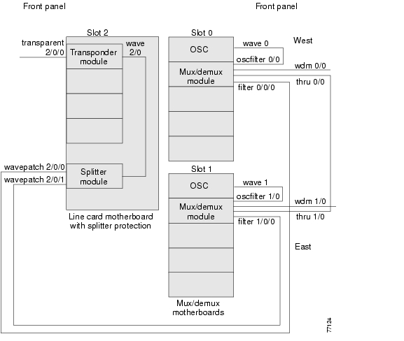
The client signal follows a path of optical cross connections through the Cisco ONS 15540 ESPx. Figure 4-5 shows an example of cross connections. Knowing the path of a signal through the shelf helps with system management and troubleshooting.
Figure 4-5 Optical Cross Connection Example on the Cisco ONS 15540 ESPx
Displaying Cross Connections
To display the signal path cross connections, use the following privileged EXEC command:
show connect [edge | intermediate [sort-channel | interface {transparent slot/subcard/port | wave slot/subcard}]]
Displays the optical connections.
Examples
The following example shows the cross connections within a system configured for splitter protection:
Switch# show connect intermediateclient/ wave wave wdmwave client patch filter trk channel------------ ------------ ------- ------ --- -------Trans2/0/0 Wave2/0 2/0/0* 0/0/0 0/0 12/0/1 1/0/0 1/0 1Trans2/2/0 Wave2/2 2/2/0* 0/0/2 0/0 32/2/1 1/0/2 1/0 3Trans2/3/0 Wave2/3 2/3/0* 0/0/3 0/0 42/3/1 1/0/3 1/0 4The following example shows the cross connections within a system configured for line card protection using splitter protected line card motherboards:
Switch# show connect intermediateclient/ wave wave wdmwave client patch filter trk channel------------ ------------ ------- ------ --- -------Trans10/0/0 Wave10/0 10/0/0* 0/3/0 0/2 2510/0/1Trans10/1/0 Wave10/1 10/1/0* 0/3/1 0/2 2610/1/1Trans10/2/0 Wave10/2 10/2/0* 0/3/2 0/2 2710/2/1Trans10/3/0 Wave10/3 10/3/0* 0/3/3 0/2 2810/3/1The following example shows how to disable protocol monitoring on a transparent interface:
Switch(config)# interface transparent 10/0/0Switch(config-if)# no monitor enableDisplaying Protocol Monitoring Configuration
To display the protocol monitoring configuration of a transparent interface, use the following EXEC command:
show interfaces {transparent slot/subcard/0 | wave slot/subcard}
Displays the transparent interface configuration.
Examples
The following example shows how to display the protocol monitoring configuration of a transparent interface:
Switch# show interfaces transparent 10/0/0Transparent10/0/0 is up, line protocol is upSignal quality: Signal degrade threshold exceededEncapsulation: Sonet Rate: oc3Signal monitoring: onForward laser control: OffConfigured threshold Group: NoneSection code violation error count(bip1): 3714369135Number of errored seconds(es): 57209Number of severely errored seconds(ses): 57209Number of severely errored framing seconds(sefs): 0Number of times SEF alarm raised: 0Number of times SF threshold exceeded: 0Number of times SD threshold exceeded: 384Loopback not setLast clearing of "show interface" counters neverHardware is transparentThe following example shows how to display the protocol monitoring configuration of a wave interface:
Switch# show interfaces wave 10/0Wave10/0 is up, line protocol is upChannel: 25 Frequency: 195.1 Thz Wavelength: 1536.61 nmSplitter Protected: NoReceiver power level: -7.0 dBmLaser safety control: OffForward laser control: OffOsc physical port: NoWavelength used for inband management: NoConfigured threshold Group: NoneSection code violation error count(bip1): 929326Number of errored seconds(es): 30Number of severely errored seconds(ses): 30Number of severely errored framing seconds(sefs): 0Number of times SEF alarm raised: 0Number of times SF threshold exceeded: 0Number of times SD threshold exceeded: 0Loopback not setLast clearing of "show interface" counters neverHardware is data_only_port
![]()
![]()
![]()
![]()
![]()
![]()
![]()
![]()
Posted: Thu Jun 3 15:53:08 PDT 2004
All contents are Copyright © 1992--2004 Cisco Systems, Inc. All rights reserved.
Important Notices and Privacy Statement.