|
|

Table Of Contents
Considerations for Using Splitter Protection
Configuring Splitter Protection
Displaying the Splitter Protection Configuration
About Client Based Line Card Protection
About Y-Cable Line Card Protection
Considerations for Using Y-Cable Based Line Card Protection
Configuring Y-Cable Based Line Card Protection
Configuring Splitter Protected Line Card Motherboards for Line Card Protection
About Trunk Fiber Based Protection
Considerations for Using Trunk Fiber Based Protection
Configuring Trunk Fiber Based Protection
Displaying Trunk Fiber Protection Configuration
Configuring APS Group Attributes
Configuring Revertive Switching
Configuring the Switchover-Enable Timer
Configuring the Wait-to-Restore Timer
Configuring the Search-For-Up Timer
Configuring the Message Timers
Requesting a Switchover or Lockout
Clearing Switchovers and Lockouts
Configuring APS
This chapter describes how to configure splitter protection and line card protection with APS (Automatic Protection Switching). This chapter contains the following sections:
•
Configuring Splitter Protection
•
•
•
•
•
•
Note
About APS
APS provides protection against signal transmission failure. The Cisco ONS 15540 ESPx supports the following APS features:
•
•
•
–
–
•
•
The 1+1 path protection architecture transmits the client signal on both the working and protection paths.
Note
http://www.cisco.com/mm/dyngraph/APS15540.html
About Splitter Protection
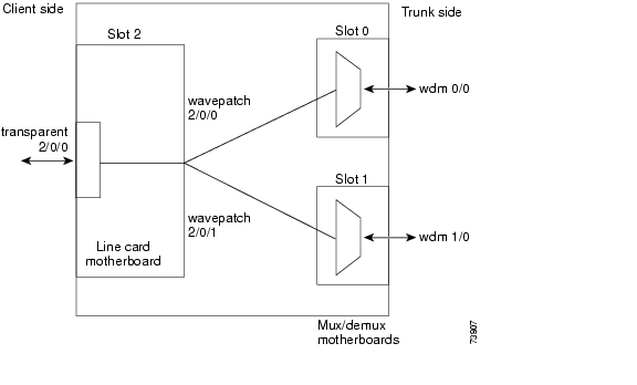
Splitter protection on the Cisco ONS 15540 ESPx provides protection against facility failure, such as trunk fiber cuts, but not transponder module failures or client equipment failures. Splitter protection internally replicates the client optical signal received from the transponder module and transmits it to mux/demux modules in both slot 0 and slot 1 (see Figure 7-1).
Figure 7-1 Splitter Protection Scheme with 2.5-Gbps Transponder Module
On the trunk side, a fiber pair, with one receive fiber and one transmit fiber, connects to one mux/demux module in slot 0. Another trunk fiber pair connects to a mux/demux module in slot 1. The client signal is transmitted through both mux/demux modules to the trunk fiber pairs. A 2 x 2 switch on the line card motherboard receives both signals from the trunk fiber pairs and selects one as the active signal. When a signal failure is detected, the 2 x 2 switch switches over to the standby signal. The standby signal then becomes the active signal.
Considerations for Using Splitter Protection
The following considerations apply when considering the use of splitter protection:
•
For detailed information on cross connecting components, refer to the Cisco ONS 15540 ESPx Planning Guide.
•
To protect against transponder module failure, use y-cable protection as described in the "About Line Card Protection" section and the "Configuring Y-Cable Based Line Card Protection" section. To protect against both transponder module failure and client failure, implement protection on the client equipment instead.
•
•
•
•
For detailed information on shelf configuration rules, refer to the Cisco ONS 15540 ESPx Planning Guide.
Configuring Splitter Protection
The following steps describe the tasks required to configure splitter protection:
Step 1
Step 2
Step 3
For each band of four or eight channels, you need two mux/demux modules that support the same channels.
For detailed information on hardware configuration rules, refer to the Cisco ONS 15540 ESPx Planning Guide.
Step 4
Ensure that the add/drop mux/demux modules are correctly interconnected with the external optical patch cables and that the cabling configuration is correctly entered with the patch command on the CLI. For detailed information on the patch command, see the "About Patch Connections" section on page 4-20.
Step 5
Caution
To enable splitter protection, use the following commands, beginning in global configuration mode:
Examples
This example shows how to associate all the wavepatch interfaces in the shelf for splitter protection and enable APS activity.
Switch#configure terminalSwitch(config)# redundancySwitch(config-red)# associate interface wavepatch */*/0 wavepatch */*/1 enableSwitch(config-red)#This example shows how to associate all the wavepatch interfaces in slot 2 for splitter protection and enable APS activity.
Switch#configure terminalSwitch(config)# redundancySwitch(config-red)# associate interface wavepatch 2/*/0 wavepatch 2/*/1 enableSwitch(config-red)#This example shows how to associate wavepatch interfaces for the transponder module in slot 3 and subcard 0 for splitter protection and modify the default attribute settings.
Switch#configure terminalSwitch(config)# redundancySwitch(config-red)# associate group dallas1Switch(config-red-aps)# aps working wavepatch 3/0/0Switch(config-red-aps)# aps protection wavepatch 3/0/1Switch(config-red-aps)# aps enableDisplaying the Splitter Protection Configuration
To display the splitter protection configuration, use the following EXEC commands:
Example
The following example shows how to display the APS splitter protection configuration:
Switch# show apsAR : APS Role, Wk: Working, Pr: ProtectionAS : APS State, Ac: Active, St: StandbyIS : Interface State, Up: Up, Dn: DownMPL: Minimum Protection Level, SD: Signal Degrade, SF: Signal FailureLOL: Loss of Light, - not currently protectedInterface AR AS IS MPL Redundant Intf Group Name~~~~~~~~~~~~~~~~~ ~~ ~~ ~~ ~~~ ~~~~~~~~~~~~~~~~~ ~~~~~~~~~~~~~~~~~~~~Wavepatch5/3/0 Wk St Up Wavepatch5/3/1 SeattleWavepatch5/3/1 Pr Ac Up LOL Wavepatch5/3/0 SeattleSwitch# show aps detailAPS Group Seattle :architecture.: 1+1, remote prov: 1+1span.........: end-to-end (network side splitter)direction....: prov: uni, current: uni, remote prov: unirevertive....: nocreated......: 14 hours, 54 minutesaps state....: associated (enabled)request timer: holddown: 5000 ms, max: 15000 ms, count 2search-up int: min: 2 secs, max: 32 secsswitched chan: 1channel ( 0): Wavepatch5/3/1 (ACTIVE - UP): channel request: no-request: transmit request: do-not-revert: receive request: no-requestchannel ( 1): Wavepatch5/3/0 (STANDBY - UP): channel request: do-not-revert: switchover count: 1: last switchover: 14 hours, 54 minutesAbout Line Card Protection
Line card protection on the Cisco ONS 15540 ESPx provides protection against both facility failures and line card failures. With line card protection, a duplicated signal is transmitted over ITU channels generated on separate line cards.
The Cisco ONS 15540 ESPx supports two types of line card protection:
•
•
About Client Based Line Card Protection
In client protection mode, both signals are transmitted to the client system. The client system decides which signal to use and when to switch over.
Note
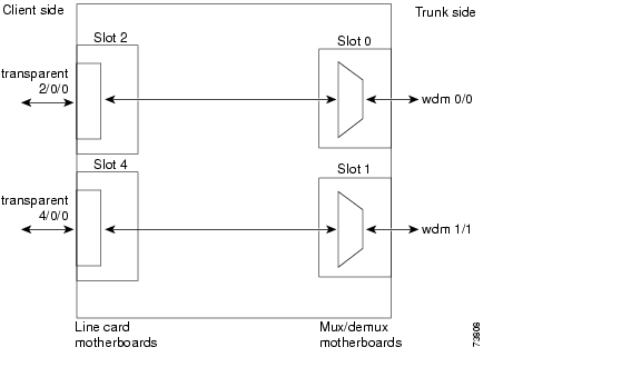
Figure 7-2 shows line card protection with a 2.5-Gbps transponder module.
Figure 7-2 Line Card Protection Scheme with 2.5-Gbps Transponder Module
The Cisco ONS 15540 ESPx supports two types of line card protection, client protection and y-cable protection. In client protection mode, both signals are transmitted to the client system. The client system decides which signal to use and when to switch over.
Note
About Y-Cable Line Card Protection
With y-cable protection, the client equipment sends only one signal to two transponder line cards using a y-cable to replicate the signal. The client equipment receives from only one transponder line card. The Cisco ONS 15540 ESPx turns on the laser at the active transparent interface, and turns off the laser on the standby transparent interface. At each receiver on the trunk side of the transponder line card, the system monitors the optical signal power level. If the system detects a failure of the active signal when an acceptable signal exists on the standby transponder line card, a switchover to the standby signal occurs by turning off the active transmitter at the client interface and turning on the standby transmitter.
Considerations for Using Y-Cable Based Line Card Protection
The following considerations apply when considering the use of line card protection:
•
For detailed information on cross connecting components, refer to the Cisco ONS 15540 ESPx Planning Guide.
•
•
•
For more information about dual shelf nodes, see "Configuring Dual Shelf Nodes"
•
•
•
Caution
Proper physical configuration of the system is critical to the operation of line card protection. For detailed information on shelf configuration rules, refer to the Cisco ONS 15540 ESPx Planning Guide.
Configuring Y-Cable Based Line Card Protection
The following is an overview of the tasks required to configure y-cable based line card protection:
Step 1
Step 2
Step 3
Step 4
Step 5
Step 6
Y-cable protection on the Cisco ONS 15540 ESPx requires configuration on the CLI. To configure y-cable protection, use the following commands, beginning in global configuration mode:
Note
Caution
Example
This example shows how to associate two transparent interfaces for y-cable line card protection with revertive switchover behavior:
Switch#configure terminalSwitch(config)# redundancySwitch(config-red)# associate group YosemiteSwitch(config-red-aps)# aps working transparent 3/0/0Switch(config-red-aps)# aps protection transparent 5/0/0Switch(config-red-aps)# aps y-cableSwitch(config-red-aps)# aps enableDisplaying the Y-Cable Protection Configuration
To display the y-cable protection configuration, use the following EXEC command:
Examples
The following example shows how to display the y-cable protection for an APS group named Yosemite:
Switch# show apsAR : APS Role, Wk: Working, Pr: ProtectionAS : APS State, Ac: Active, St: StandbyIS : Interface State, Up: Up, Dn: DownMPL: Minimum Protection Level, SD: Signal Degrade, SF: Signal FailureLOL: Loss of Light, - not currently protectedInterface AR AS IS MPL Redundant Intf Group Name~~~~~~~~~~~~~~~~~ ~~ ~~ ~~ ~~~ ~~~~~~~~~~~~~~~~~ ~~~~~~~~~~~~~~~~~~~~Transparent2/3/0 Wk Ac Up SD Transparent4/3/0 YosemiteTransparent4/3/0 Pr St Up Transparent2/3/0 YosemiteSwitch# show aps group YosemiteAPS Group Yosemite :architecture.: 1+1, remote prov: 1+1span.........: end-to-end (client side y-cable)direction....: prov: uni, current: uni, remote prov: birevertive....: nocreated......: 14 hours, 53 minutesaps state....: associated (enabled)request timer: holddown: 5000 ms, max: 15000 ms, count 2switched chan: 0channel ( 0): Transparent4/3/0 (STANDBY - UP), Wave4/3 (UP): channel request: no-request: transmit request: no-request: receive request: no-requestchannel ( 1): Transparent2/3/0 (ACTIVE - UP), Wave2/3 (UP): channel request: no-request: switchover count: 0: last switchover: neverThe following example shows how to display the y-cable protection for an APS group on a 10-GE card, named y-protect:
Switch# show aps group y-protectAPS Group y-protect :architecture.:1+1, remote prov:1+1span.........:end-to-endprot. mode...:client side y-cabledirection....:prov:uni, current:uni, remote prov:unirevertive....:noaps state....:enabled (associated)request timer:holddown:5000 ms, max:15000 ms, count 2msg-channel..:auto (up on cdl dcc)created......:2 minutesauto-failover:enabledtransmit k1k2:no-request, 0, 0, 1+1, unireceive k1k2:no-request, 0, 0, 1+1, uniswitched chan:0protection(0):TenGigEthernetPhy9/1 (STANDBY - UP), WaveEthernetPhy9/1(UP):channel request:no-request:switchover count:0:last switchover:neverworking...(1):TenGigEthernetPhy10/0 (ACTIVE - UP), WaveEthernetPhy10/0(UP):channel request:no-request:switchover count:0:last switchover:neverConfiguring Splitter Protected Line Card Motherboards for Line Card Protection
Normally, you would use unprotected line card motherboards for line card protection configurations. However, you can use splitter protected line card motherboards instead by shutting down the wavepatch interfaces to one of the mux/demux motherboards.
To configure line card protection on splitter protected line card motherboards, use the following commands, beginning in global configuration mode:
Step 1
Switch(config)# interface wavepatch slot/subcard/port
Switch(config-if)#
Selects the wavepatch interface to configure and enters interface configuration mode.
Step 2
Switch(config-if)# shutdown
Disables the wavepatch interface.
Step 3
Switch(config-if)# exit
Switch(config)#
Returns to global configuration mode.
Repeat Step 1 through Step 3 for one wavepatch interface per wavepatch pair on splitter protected line card motherboards.
Examples
For the following examples, assume that the line card motherboards shown in Figure 7-2 have splitter protection.
The following example shows how to disable all wavepatch interfaces on the line card motherboard in slot 2 that connect to the mux/demux motherboard in slot 1:
Switch(config)# interface wavepatch 2/0/1Switch(config-if)# shutdownSwitch(config-if)# exitSwitch(config)# interface wavepatch 2/1/1Switch(config-if)# shutdownSwitch(config-if)# exitSwitch(config)# interface wavepatch 2/2/1Switch(config-if)# shutdownSwitch(config-if)# exitSwitch(config)# interface wavepatch 2/3/1Switch(config-if)# shutdownSwitch(config-if)# exitSwitch(config)#The following example shows how to disable all wavepatch interfaces on the line card motherboard in slot 4 that connect to the mux/demux motherboard in slot 0:
Switch(config)# interface wavepatch 4/0/0Switch(config-if)# shutdownSwitch(config-if)# exitSwitch(config)# interface wavepatch 4/1/0Switch(config-if)# shutdownSwitch(config-if)# exitSwitch(config)# interface wavepatch 4/2/0Switch(config-if)# shutdownSwitch(config-if)# exitSwitch(config)# interface wavepatch 4/3/0Switch(config-if)# shutdownSwitch(config-if)# exitSwitch(config)#About Trunk Fiber Based Protection
The PSM (protection switch module) provides trunk fiber based protection for Cisco ONS 15540 ESPx systems configured in point-to-point topologies. This type of protection only provides protection against trunk fiber cuts, not specific channel failure as provided by splitter and line card based schemes. However, this protection scheme allows for much simpler shelf configurations in topologies where per channel protection is not required.
Figure 7-3 shows trunk fiber based protection configured with a transponder module.
Figure 7-3 Trunk Fiber Based Protection Scheme
Considerations for Using Trunk Fiber Based Protection
The following considerations apply when using trunk fiber based protection:
•
•
•
•
Configuring Trunk Fiber Based Protection
To configure trunk fiber based protection on the PSMs, perform the following steps, beginning in global configuration mode:
Examples
The following example shows how to configure trunk fiber protection:
Switch(config)# redundancySwitch(config-red)# associate group psm-groupSwitch(config-red-aps)# aps working wdmsplit 0/1/0Switch(config-red-aps)# aps protection wdmsplit 0/1/1Switch(config-red-aps)# aps message-channel ip far-end group-name psm-group ip-address 172.18.44.93Switch(config-red-aps)# aps enableDisplaying Trunk Fiber Protection Configuration
To display the trunk fiber configuration, use the following EXEC command:
show aps {detail | group name | interface wavepatch slot/subcard/port}
Displays detailed APS configuration information for groups and interfaces.
Note
Examples
The following example shows how to display the protocol encapsulation configuration of a wdmsplit interface:
Switch# show aps group psm-groupAPS Group psm-group :architecture.: 1+1, remote prov: 1+1span.........: end-to-endprot. mode...: network side wdm splitterdirection....: prov: bi, current: bi, remote prov: birevertive....: noaps state....: enabled (associated)request timer: holddown: 5000 ms, max: 15000 ms, count 2msg-channel..: ip (up), psm-group, 172.18.44.93created......: 22 hours, 11 minutesauto-failover: disabledtransmit k1k2: sf-lp, 0, 0, 1+1, bireceive k1k2: reverse-request, 0, 0, 1+1, biswitched chan: 0protection(0): WdmSplit0/0/1 (STANDBY - DOWN): channel request: sf-lp: switchover count: 7: last switchover: 18 minutesworking...(1): WdmSplit0/0/0 (ACTIVE - UP): channel request: no-request: switchover count: 7: last switchover: 18 minutesConfiguring APS Group Attributes
This section describes APS group attributes and how to configure them.
Configuring Revertive Switching
The Cisco ONS 15540 ESPx supports revertive switching for y-cable and trunk fiber protection. When revertive switching is configured, the system automatically switches back from the protection interface to the working interface. This automatic switchover occurs after the condition that caused the switchover to the protection interface is resolved and the switchover-enable timer has expired.
To configure revertive switching, use the following commands, beginning in global configuration mode:
Example
The following example shows how to configure revertive switching for a y-cable protected APS group:
Switch#configure terminalSwitch(config)# redundancySwitch(config-red)# associate group blueSwitch(config-red-aps)# aps working transparent 4/0/0Switch(config-red-aps)# aps protection transparent 8/0/0Switch(config-red-aps)# aps y-cableSwitch(config-red-aps)# aps revertiveSwitch(config-red-aps)# aps enableDisplaying the Revertive Switching Configuration
To display the revertive switching configuration, use the following EXEC command:
Example
The following example shows how to display the path switching configuration for an APS group named blue:
Switch# show aps group blueAPS Group blue:architecture.: 1+1, remote prov: 1+1span.........: end-to-endprot. mode...: client side y-cabledirection....: prov: uni, current: uni, remote prov: unirevertive....: yes, wtr: 300 secs (not running)
aps state....: enabled (associated)request timer: holddown: 5000 ms, max: 15000 ms, count 2msg-channel..: auto (up on osc)created......: 4 days, 23 hours, 16 minutesauto-failover: enabledtransmit k1k2: no-request, 0, 0, 1+1, unireceive k1k2: no-request, 0, 0, 1+1, uniswitched chan: 0protection(0): Transparent8/0/0 (STANDBY - UP), Wave8/0 (UP): channel request: no-request: switchover count: 2: last switchover: 3 days, 23 hours, 16 minutesworking...(1): Transparent4/0/0 (ACTIVE - UP), Wave4/0 (UP): channel request: no-request: switchover count: 1: last switchover: 4 days, 53 minutesAbout Path Switching
The Cisco ONS 15540 ESPx supports per-channel unidirectional and bidirectional 1+1 path switching. When a signal is protected and the signal fails, or in some cases degrades, on the active path, the system automatically switches from the active network path to the standby network path.
Signal failures can be total loss of light caused by laser failures, by fiber cuts between the Cisco ONS 15540 ESPx and the client equipment, or by other equipment failure. Loss of light failures cause switchovers for both splitter protected and y-cable protected signals.
For y-cable protected signals, you can also configure alarm thresholds to cause a switchover when the signal error rate reaches an unacceptable level. For information about configuring alarm thresholds, see the "Configuring Alarm Thresholds" section on page 4-9.
Note
The Cisco ONS 15540 ESPx implements path switching using a SONET-compliant APS channel protocol over the in-band message channel or the OSC (optical supervisory channel) on the protection path, or on the IP management connection.
Note
Figure 7-4 shows a simple point-to-point configuration with splitter protection. The configured working path carries the active signal, and the configured protection path carries the standby signal.
Figure 7-4 Active and Standby Path Configuration Example
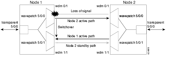
Figure 7-5 shows the behavior of unidirectional path switching when a loss of signal occurs. For the two node example network, unidirectional path switching operates as follows:
•
•
•
•
Now the nodes are communicating along different paths.
Figure 7-5 Unidirectional Path Switching Example
Figure 7-6 shows the behavior of bidirectional path switching when a loss of signal occurs. For the two node example network, bidirectional path switching operates as follows:
•
•
•
•
•
Both node 1 and node 2 communicate on the same path.
Figure 7-6 Bidirectional Path Switching Overview
Configuring Path Switching
To configure unidirectional or bidirectional path switching, use the following commands, beginning in global configuration mode:
Step 1
Switch(config)# redundancy
Switch(config-red)#
Enters redundancy configuration mode.
Step 2
Switch(config-red)# associate group name
Switch(config-red-aps)#
Selects the interfaces to associate and enters APS configuration mode.
Note
Step 3
Switch(config-red-aps)# aps disable
Disables APS activity between the interfaces.
Note
Step 4
Switch(config-red-aps)# aps direction {unidirectional | bidirectional}
Specifies the type of path switching. The default behavior is unidirectional.
Step 5
Switch(config-red-aps)# aps working {transparent slot/subcard/0 | wavepatch slot/subcard/port | tengigethernetphy slot/subcard | wdmsplit slot/subcard/port}
Configures the working path interface.
Step 6
Switch(config-red-aps)# aps protection {transparent slot/subcard/0 | wavepatch slot/subcard/port | tengigethernetphy slot/subcard | wdmsplit slot/subcard/port}
Configures the protection path interface.
Step 7
Switch(config-red-aps)# aps timer oscp holddown milliseconds count number
Changes the APS channel protocol holddown timer and message count values. The default is 5000 milliseconds and a count of 2
Step 8
Switch(config-red-aps)# aps timer oscp max-interval seconds
Changes the APS channel protocol maximum interval timer for waiting for a message. The default is 15 seconds.
Repeat Step 1 through Step 8 on the corresponding transparent interface on the other node that adds and drops, or terminates, the channel.
Step 9
Switch(config-red-aps)# aps enable
Enables APS activity between the interfaces.
Note
Note
Examples
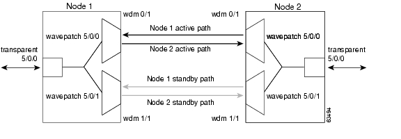
Figure 7-7 shows the active and standby paths between node 1 and node 2 with splitter protection.
Figure 7-7 Bidirectional Path Switching Example with Splitter Protection
The following example shows how to configure one channel in the example network for bidirectional path switching using the default working and protection path interfaces:
Node1#configure terminalNode1(config)# redundancyNode1(config-red)# associate group redNode1(config-red-aps)# aps working wavepatch 5/0/0Node1(config-red-aps)# aps protection wavepatch 5/0/1Node1(config-red-aps)# aps bidirectionalNode1(config-red-aps)# aps enableNode2#configure terminalNode2(config)# redundancyNode2(config-red)# associate group blueNode2(config-red-aps)# aps working wavepatch 5/0/0Node2(config-red-aps)# aps protection wavepatch 5/0/1Node2(config-red-aps)# aps bidirectionalNode2(config-red-aps)# aps enableFigure 7-8 shows the active and standby paths between node 1 and node 2 with y-cable protection.
Figure 7-8 Bidirectional Path Switching Example with Y-Cable Protection
The following example shows how to configure one channel in the example network for bidirectional path switching and configure the working and protection path interfaces:
Node1#configure terminalNode1(config)# redundancyNode1(config-red)# associate group alphaNode1(config-red-aps)# aps working transparent 5/0/0Node1(config-red-aps)# aps protection transparent 3/0/0Node1(config-red-aps)# aps direction bidirectionalNode1(config-red-aps)# aps y-cableNode1(config-red-aps)# aps enableNode2#configure terminalNode2(config)# redundancyNode2(config-red)# associate group alphaNode2(config-red-aps)# aps working transparent 5/0/0Node2(config-red-aps)# aps protection transparent 3/0/0Node2(config-red-aps)# aps direction bidirectionalNode2(config-red-aps)# aps y-cableNode2(config-red-aps)# aps enableChanging the Path Switching Direction for Y-Cable Protection
To change the path switching direction for a y-cable protection configuration, use the following commands:
Step 1
Switch# show aps group name
Displays the current standby interface in the APS group information.
Step 2
Switch# configure terminal
Switch(config)#
Enters global configuration mode.
Step 3
Switch(config)# interface transparent slot/subcard/0
Switch(config-if)#
Enters interface configuration mode for the standby interface.
Step 4
Switch(config-if)# shutdown
Disables the interface.
Step 5
Switch(config-if)# exit
Switch(config)#
Exits interface configuration mode.
Step 6
Switch(config)# redundancy
Switch(config-red)#
Enters redundancy configuration mode.
Step 7
Switch(config-red)# associate group name
Switch(config-red-aps)#
Selects the interfaces to associate and enters APS configuration mode.
Note
Step 8
Switch(config-red-aps)# aps disable
Disables APS activity between the interfaces.
Note
Step 9
Switch(config-red-aps)# aps direction {unidirectional | bidirectional}
Specifies the new path switching operation.
Step 10
Switch(config-red-aps)# aps enable
Enables APS activity between the interfaces.
Step 11
Switch(config-red-aps)# exit
Switch(config)#
Exits APS configuration mode.
Step 12
Switch(config-red)# exit
Switch(config)#
Exits redundancy configuration mode.
Step 13
Switch(config)# interface transparent slot/subcard/0
Switch(config-if)#
Enters interface configuration mode for the standby interface.
Step 14
Switch(config-if)# no shutdown
Disables the interface.
Step 15
Switch(config-if)# end
Switch#
Returns to privileged EXEC mode.
Repeat Step 1 through Step 15 on the corresponding transparent interface on the other node that adds and drops, or terminates, the channel.
Example
The following example shows how to change the path switching operation for a y-cable APS group from unidirectional to bidirectional:
Node1# show aps group DenverAPS Group Denver :architecture.: 1+1, remote prov: 1+1span.........: end-to-end (client side y-cable)direction....: prov: uni, current: uni, remote prov: unirevertive....: nocreated......: 14 hours, 53 minutesaps state....: associated (enabled)request timer: holddown: 5000 ms, max: 15000 ms, count 2switched chan: 0: channel request: no-request: transmit request: no-request: receive request: no-requestchannel ( 1): Transparent2/3/0 (ACTIVE - UP), Wave2/3 (UP): channel request: no-request: switchover count: 0: last switchover: neverNode1#configure terminalNode1(config)#interface transparent 4/3/0Node1(config-if)#shutdownNode1(config-if)#exitNode1(config)# redundancyNode1(config-red)# associate group DenverNode1(config-red-aps)# aps disableNode1(config-red-aps)# aps direction bidirectionalNode1(config-red-aps)# aps enableNode1(config-red-aps)# exitNode1(config-red)# exitNode1(config)#interface transparent 4/3/0Node1(config-if)#no shutdownNode1(config-if)#endNode1#Node2# show aps group DenverAPS Group Denver :architecture.: 1+1, remote prov: 1+1span.........: end-to-end (client side y-cable)direction....: prov: uni, current: uni, remote prov: birevertive....: nocreated......: 14 hours, 53 minutesaps state....: associated (enabled)request timer: holddown: 5000 ms, max: 15000 ms, count 2switched chan: 0: channel request: no-request: transmit request: no-request: receive request: no-requestchannel ( 1): Transparent2/3/0 (ACTIVE - UP), Wave2/3 (UP): channel request: no-request: switchover count: 0: last switchover: neverNode2#configure terminalNode2(config)#interface transparent 4/3/0Node2(config-if)#shutdownNode2(config-if)#exitNode2(config)# redundancyNode2(config-red)# associate group DenverNode2(config-red-aps)# aps disableNode2(config-red-aps)# aps direction bidirectionalNode2(config-red-aps)# aps enableNode2(config-red-aps)# exitNode2(config-red)# exitNode2(config)#interface transparent 4/3/0Node2(config-if)#no shutdownNode2(config-if)#endNode2#Displaying the Path Switching Configuration
To display the path switching configuration, use the following EXEC command:
Example
The following example shows how to display the path switching configuration for an APS group named blue:
Switch# show aps group blueAPS Group blue:architecture.: 1+1, remote prov: 1+1span.........: end-to-endrevertive....: nocreated......: 26 minutesaps state....: associatedrequest timer: holddown: 5000 ms, max: 15 secs, count 2switched chan: 0channel ( 0): Wavepatch8/0/1 (STANDBY - UP): channel request: no-request: transmit request: no-request: receive request: no-requestchannel ( 1): Wavepatch8/0/0 (ACTIVE - UP): channel request: no-request: switchover count: 0: last switchover: neverConfiguring the Switchover-Enable Timer
The switchover-enable timer on the Cisco ONS 15540 ESPx prevents any automatic switchover from the protection path to the working path until it has expired. When it expires, switchovers occur only if there is no fault on the working path and there is no overriding switchover request in effect.
To configure the switchover-enable timer, use the following commands, beginning in global configuration mode:
Example
The following example shows how to configure the minimum interval value for the switchover-enable timer for an APS group.
Switch(config)# redundancySwitch(config-red)# associate group ycSwitch(config-red-aps)# aps disableSwitch(config-red-aps)# aps timer switchover-enable min-interval 10Switch(config-red-aps)# aps enableDisplaying the Switchover-Enable Timer Configuration
To display the switchover-enable timer configuration, use the following EXEC command:
Example
The following example shows how to display the switchover-enable timer configuration for an APS group:
Switch# show running-configBuilding configuration...Current configuration : 3403 bytes!version 12.1no service padservice timestamps debug uptimeservice timestamps log uptimeno service password-encryptionservice internal!hostname M1!redundancykeepalive-timer 4000keepalive-threshold 12associate group ycaps working Transparent8/0/0aps protection Transparent8/3/0aps y-cableaps enable<Information deleted.>Configuring the Wait-to-Restore Timer
The wait-to-restore timer on the Cisco ONS 15540 ESPx prevents oscillations when revertive switching is enabled for y-cable line card protection configurations. If the preferred working signal in a y-cable line card protection configuration is unstable, the wait-to-restore timer prevents possible data loss that could result from frequent switchovers.
To configure the wait-to-restore timer, use the following commands, beginning in global configuration mode:
Example
The following example shows how to configure the wait-to-restore timer value for an APS group.
Switch(config)# redundancySwitch(config-red)# associate group blueSwitch(config-red-aps)# aps disableSwitch(config-red-aps)# aps timer wait-to-restore 240Switch(config-red-aps)# aps enableDisplaying the Wait-to-Restore Timer Configuration
To display the wait-to-restore timer configuration, use the following EXEC command:
Example
The following example shows how to display the wait-to-restore timer configuration for an APS group named blue:
Switch# show aps group blueAPS Group blue:architecture.: 1+1, remote prov: unknownspan.........: end-to-endprot. mode...: client side y-cabledirection....: prov: uni, current: uni, remote prov: unknownaps state....: enabled (associated)request timer: holddown: 5000 ms, max: 15000 ms, count 2msg-channel..: auto (down)created......: 4 days, 25 minutesauto-failover: enabledtransmit k1k2: wait-to-restore, 1, 1, 1+1, unireceive k1k2: no-request, 0, 0, unknown, unknownswitched chan: 1protection(0): Transparent8/3/0 (ACTIVE - UP), Wave8/3 (UP): channel request: no-request: switchover count: 0: last switchover: neverworking...(1): Transparent9/3/0 (STANDBY - UP), Wave9/3 (UP): channel request: wait-to-restore: switchover count: 1: last switchover: 4 days, 25 minutesConfiguring the Search-For-Up Timer
The search-for-up timer on the Cisco ONS 15540 ESPx causes the system to wait for a splitter protection connection to come up before checking the other splitter protection connection.
When both members of a splitter pair are down, the system first checks one signal for the minimum time interval. If the splitter protection connection does not come up, the system checks the other connection and doubles the time interval. This process repeats until the maximum timer interval is reached or exceeded. Checking continues at the maximum timer interval until one of the splitter protection connections becomes active.
To configure the search-for-up timer, use the following commands, beginning in global configuration mode:
Example
The following example shows how to configure the search-for-up timer value for an APS group.
Switch(config)# redundancySwitch(config-red)# associate group ycSwitch(config-red-aps)# aps disableSwitch(config-red-aps)# aps timer search-for-up 4 16Switch(config-red-aps)# aps enableDisplaying the Search-For-Up Timer Configuration
To display the search-for-up timer configuration, use the following EXEC command:
Example
The following example shows how to display the search-for-up configuration for an APS group:
Switch# show aps group splitterAPS Group splitter :architecture.: 1+1, remote prov: unknownspan.........: end-to-endprot. mode...: network side splitterdirection....: prov: uni, current: uni, remote prov: unknownrevertive....: noaps state....: enabled (associated)request timer: holddown: 5000 ms, max: 15000 ms, count 2search-up-int: min: 4 secs, max: 16 secsmsg-channel..: auto (down)created......: 3 minutesauto-failover: enabledtransmit k1k2: no-request, 0, 0, 1+1, unireceive k1k2: no-request, 0, 0, unknown, unknownswitched chan: 0protection(0): Wavepatch8/0/1 (STANDBY - UP): channel request: no-request: switchover count: 0: last switchover: neverworking...(1): Wavepatch8/0/0 (ACTIVE - UP): channel request: no-request: switchover count: 0: last switchover: neverConfiguring the Message Timers
The Cisco ONS 15540 ESPx provides two message timers, the APS message holddown timer and the APS message maximum inactivity interval timer. The APS message holddown timer prevents APS channel protocol message flooding. The maximum inactivity interval timer determines how often to send the inactivity messages to ensure that the APS channel protocol is still functioning between the nodes.
To configure the message timers, use the following commands, beginning in global configuration mode:
Example
The following example shows how to configure the message timer values for an APS group.
Switch(config)# redundancySwitch(config-red)# associate group ycSwitch(config-red-aps)# aps disableSwitch(config-red-aps)# aps timer message holddown 4000 3Switch(config-red-aps)# aps timer message max-interval 10Switch(config-red-aps)# aps enableDisplaying the Message Timer Configuration
To display the message timer configuration, use the following EXEC command:
Example
The following example shows how to display the message timer configuration for an APS group:
Switch# show aps group blueAPS Group blue :architecture.: 1+1, remote prov: unknownspan.........: end-to-endprot. mode...: network side splitterdirection....: prov: uni, current: uni, remote prov: unknownrevertive....: noaps state....: enabled (associated)search-up-int: min: 2 secs, max: 32 secsmsg-channel..: auto (down)created......: 3 minutesauto-failover: enabledtransmit k1k2: no-request, 0, 0, 1+1, unireceive k1k2: no-request, 0, 0, unknown, unknownswitched chan: 0protection(0): Wavepatch8/0/1 (STANDBY - UP): channel request: no-request: switchover count: 0: last switchover: neverworking...(1): Wavepatch8/0/0 (ACTIVE - UP): channel request: no-request: switchover count: 0: last switchover: neverSwitchovers and Lockouts
In APS, you can switch a channel signal from one path to another, or you can lock out a switchover altogether while performing system maintenance.
A switchover of the channel signal from the working path to protection path is useful when
upgrading or maintaining the system, or in cases where a signal failure caused a switchover. In the case of splitter protection, once the cause of the problem has been corrected, the system does not automatically revert to using the original working path. The switchover to the formerly failed interface must be requested from the CLI. The interface originally configured as the working path might be preferred because of its link loss characteristics or because of its distance advantage. For example, some protocols, such as ESCON, experience lower data throughput at increasing distances, so moving the signal back to the shorter path might be advised.
A lockout prevents a switchover of the active signal from the working path to the protection path. This is useful when upgrading or maintaining the system, or when the signal on the protection path has degraded or failed.
The Cisco ONS 15540 ESPx supports APS switchover and lockout requests from the CLI. These requests have priorities depending on the condition of the protection signal and the existence of other switchover requests. There are three types of switchover requests:
•
•
•
In summary, the priority order is:
1.
2.
3.
4.
5.
6.
If a request or condition of a higher priority is in effect, a lower priority request is rejected.
Note
Requesting a Switchover or Lockout
To prevent switchovers to the protection signal, or to request a signal switchover, use the following commands in privileged EXEC mode:
Examples
The following example shows how to request a forced switchover from working to protection except if a lockout is in effect on the protection path:
Switch# aps switch blue force working-to-protectionThe following example shows how to prevent a switchover to the protection path:
Switch# aps lockout Wavepatch3/0/0Displaying Switchover and Lockout Request Status
To display a pending switchover request, use the following command in privileged EXEC mode:
The following example shows how to display the switchover request status on an APS group:
Switch# show aps group yellowAPS Group yellow:architecture.: 1+1, remote prov: 1+1span.........: end-to-end (client side y-cable)direction....: prov: uni, current: uni, remote prov: birevertive....: nocreated......: 15 hours, 1 minuteaps state....: associated (enabled)request timer: holddown: 5000 ms, max: 15000 ms, count 2switched chan: 0channel ( 0): Transparent4/3/0 (STANDBY - UP), Wave4/3 (UP): receive request: no-requestchannel ( 1): Transparent2/3/0 (ACTIVE - UP), Wave2/3 (UP): channel request: no-request: switchover count: 0: last switchover: neverClearing Switchovers and Lockouts
A lockout or a forced or manual switchover request stays in effect until the system reboots. You can manually clear these requests from the CLI.
To clear an APS switchover or lockout, use the following privileged EXEC command:
aps clear group-name
Clears APS switch request or lockout on an associated interface pair.
Example
The following example shows how to clear the switchover requests on an associated interface pair using the default group name:
Switch# aps clear Wavepatch10/0/0Displaying Switchover and Lockout Clear Status
To display a pending switchover request, use the following command in privileged EXEC mode:
The following example shows how to display the switchover requests status on an APS group:
Switch# show aps group blueAPS Group blue :architecture.: 1+1, remote prov: 1+1span.........: end-to-end (client side y-cable)direction....: prov: uni, current: uni, remote prov: birevertive....: nocreated......: 15 hours, 1 minuteaps state....: associated (enabled)request timer: holddown: 5000 ms, max: 15000 ms, count 2switched chan: 0channel ( 0): Transparent10/0/0 (STANDBY - UP): receive request: no-requestchannel ( 1): Transparent8/0/0 (ACTIVE - UP): channel request: no-request: switchover count: 0: last switchover: never
![]()
![]()
![]()
![]()
![]()
![]()
![]()
![]()
Posted: Thu Jun 3 15:21:45 PDT 2004
All contents are Copyright © 1992--2004 Cisco Systems, Inc. All rights reserved.
Important Notices and Privacy Statement.