|
|

Table Of Contents
Monitoring Your Network Topology
Hardware Guidelines for Using OSC
Configuring CDP Topology Discovery on Wdm and Tengigethernetphy Interfaces
Configuring the Hello Interval Timer
Configuring the Hello Hold-Down Timer
Configuring the Inactivity Factor
Displaying the OSCP Configuration
Verifying Connectivity Over the OSC
Configuring IP on Ethernetdcc Interfaces for the In-Band Message Channel
Displaying the Ethernetdcc Interface Configuration
Verifying Connectivity over the In-Band Message Channel
Monitoring Without the OSC or In-Band Message Channel
Setting Up Connections to Individual Nodes
Manually Configuring the Network Topology
Configuring Interfaces in the Network Topology
Displaying Topology Information
Installing and Configuring Embedded CiscoView
Displaying Embedded CiscoView Information
Monitoring Your Network Topology
This chapter describes how to configure and manage your network topology. This chapter includes the following sections:
•
Monitoring Without the OSC or In-Band Message Channel
•
•
About the OSC
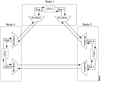
As described in the "Optical Supervisory Channel" section on page 1-9, the Cisco ONS 15540 ESPx dedicates a separate channel (channel 0) for the OSC (optical supervisory channel), which is used for network control and management information between Cisco ONS 15540 ESPx systems on the network. The OSC is carried on the same fiber as the data channels (channels 1 through 32), but it carries no client data traffic.
Figure 11-1 shows the path of the OSC in a protected ring configuration. The OSC signal is generated by a laser on each mux/demux motherboard and is sent in both directions from the node; both receive signals are monitored to maintain communication with the neighboring nodes. The OSC signal terminates at each node.
Figure 11-1 OSC Signal Path in a Ring Configuration
The OSC performs the following functions:
•
•
•
Hardware Guidelines for Using OSC
The OSC signal is generated using a dedicated laser on the mux/demux motherboards. To provide protection against failure of the laser or a fiber break in protected configurations (point-to-point or ring), the following rules apply:
•
•
•
For more information on hardware configuration rules, refer to the Cisco ONS 15540 ESPx Planning Guide.
Configuring CDP
CDP is primarily used to obtain protocol addresses of neighboring devices and to discover the platform of those devices. For a full description of CDP and details on configuring the protocol, refer to the
Cisco IOS Configuration Fundamentals Configuration Guide. For a full description of the CDP commands, refer to the Cisco IOS Configuration Fundamentals Command Reference.On the Cisco ONS 15540 ESPx, you can configure CDP at both the global level and the interface level. The global-level CDP configuration sets the attributes for the entire system. The interface-level configuration identifies interfaces connected to the client equipment and to the trunk interface to CDP. Because there are only optical connections to the client equipment, you must explicitly identify the transparent interfaces connected to the client equipment. On wdm interfaces, you can choose to provide the information about the interface in the CLI or you can let CDP discover it.
Note
Configuring Global CDP
To configure CDP on your Cisco ONS 15540 ESPx, use the following commands in global configuration mode:
Examples
In the following example, the CDP packets being sent from your device should be held by the receiving device for 60 seconds before being discarded:
Switch(config)# cdp holdtime 60In the following example, CDP updates are sent every 80 seconds:
Switch(config)# cdp timer 80Displaying the Global CDP Configuration
To display the configured CDP values, use the following EXEC command:
Example
The following example shows how to display the configured CDP values:
Switch> show cdp
Global CDP information:Sending CDP packets every 60 secondsSending a holdtime value of 180 secondsSending CDPv2 advertisements is enabledDisplaying Global CDP Information
You can display information gathered by CDP, including a specific neighbor device listed in the CDP table, the interfaces on which CDP is enabled, and the traffic between devices gathered using CDP.
To display the CDP information, use the following EXEC commands:
Example
The following example shows how to display CDP status and activity information:
Switch1# show cdp entry *-------------------------Device ID: Switch2Entry address(es):IP address: 10.1.1.2Platform: cisco , Capabilities: RouterInterface: Wave0, Port ID (outgoing port): Wave0Holdtime : 176 secVersion :Cisco Internetwork Operating System SoftwareIOS (tm) ONS-15540 Software (manopt-I-M), Experimental Version 12.1 [koj-ons 122]Copyright (c) 1986-2001 by cisco Systems, Inc.Compiled Mon 30-Apr-01 12:04 by kojadvertisement version: 2Switch1# show cdp interfaceWave0 is up, line protocol is upEncapsulation UNKNOWNSending CDP packets every 60 secondsHoldtime is 180 secondsSwitch1# show cdp neighborsCapability Codes: R - Router, T - Trans Bridge, B - Source Route BridgeS - Switch, H - Host, I - IGMP, r - RepeaterDevice ID Local Intrfce Holdtme Capability Platform Port IDSwitch2 Wave0 158 R Wave0Switch1# show cdp trafficCDP counters :Total packets output: 18, Input: 20Hdr syntax: 0, Chksum error: 0, Encaps failed: 0No memory: 0, Invalid packet: 0, Fragmented: 0CDP version 1 advertisements output: 0, Input: 0CDP version 2 advertisements output: 18, Input: 20Clearing Global CDP Information
You can reset the CDP traffic counters to zero and clear the table that contains the CDP neighbor information. To clear the CDP information, use the following privileged EXEC commands:
clear cdp counters
Resets the CDP traffic counters to zero.
clear cdp table
Clears the table that contains the CDP neighbor information.
Configuring CDP Topology Discovery on Wdm and Tengigethernetphy Interfaces
You can enable CDP topology discovery on the wdm interfaces that connect to the trunk fiber and on tengigethernetphy interfaces connected to equipment that supports CDP. CDP then automatically advertises interface information to neighboring nodes.
Note
To configure CDP topology discovery on wdm interfaces, perform the following steps, beginning in global configuration mode:
Examples
The following example shows how to enable CDP topology discover on a wdm interface:
Switch(config)# interface wdm 0/0Switch(config-if)# topology neighbor cdpThe following example shows how to disable CDP topology discovery on a wdm interface:
Switch(config)# interface wdm 0/0Switch(config-if)# topology neighbor disableDisplaying CDP Information
You can display interface-level information gathered by CDP, including neighboring devices.
To display the CDP information for an interface, use the following EXEC commands:
Example
Switch# show topology neighborPhysical Topology:Local Port Neighbor Node Neighbor Port---------- ------------- -------------Wd0/0 Node1 wdm1/1Wd0/1 Node2 wdm0/2Trans8/1/0 Router1 gigabitethernet1/1Switch# show topologyGlobal Physical Topology configuration:Maximum Hold Time = 300 secsTrap interval = 60 secsConfiguring OSCP
The configurable parameters of the OSCP are described in the following sections.
Note
Configuring the Hello Interval Timer
The OSCP sends Hello packets to adjacent nodes at a configured interval. When five packets fail to get a response from the receiving node, that node is declared "down." By decreasing the interval at which Hello packets are sent, reaction time to a failed node can be lessened. Increasing the interval reduces the amount of Hello packet traffic.
To configure the OSCP Hello timer interval, use the following global configuration command:
oscp timer hello interval milliseconds
Configures the Hello interval timer in milliseconds. The default value is 3000 milliseconds.
Example
The following example shows how to set the Hello interval to 500 milliseconds:
Switch(config)# oscp timer hello interval 500Configuring the Hello Hold-Down Timer
The Hello hold-down timer specifies the interval during which no more than one Hello packet can be sent. If more than one Hello packet is generated during the hold-down period, the extra packets are delayed. Increasing the hold-down timer limits the number of Hello packets triggered in response to Hello packets received from a neighboring node and reduces the likelihood of Hello packets flooding the OSC.
To configure the OSCP Hello hold-down timer, use the following global configuration command:
oscp timer hello holddown milliseconds
Configures the Hello hold-down timer in milliseconds. The default value is 100 milliseconds.
Example
The following example shows how to set the Hello hold-down timer to 2000 milliseconds:
Switch(config)# oscp timer hello holddown 2000Configuring the Inactivity Factor
The OSCP inactivity factor determines whether or not to declare a link down. The inactivity factor is multiplied by the advertised Hello timer interval of the other node to produce the inactivity time interval. If the system does not receive OSCP packets from the other node before the expiration of the inactivity time interval, the link is declared down.
To configure the OSCP inactivity factor, use the following global configuration command:
oscp timer inactivity-factor factor
Configures inactivity factor as a multiple of the Hello interval. The default multiplier is 5.
Example
The following example shows how to configure the inactivity factor to 10 times the Hello interval value:
Switch(config)# oscp timer inactivity-factor 10Displaying the OSCP Configuration
You can display the OSCP version, node ID, interfaces, and configured protocol parameters. To display the OSCP configuration, use the following EXEC command:
Example
The following example shows the OSCP configuration:
Switch(config)# show oscp infoOSCP protocol version 1, Node ID 0001.6447.a240No. of interfaces 3, No. of neighbors 0Hello interval 3000 msec, inactivity factor 5,Hello hold-down 200 msecSupported OSCP versions:newest 1, oldest 1Displaying OSCP Neighbors
You can display the information for neighboring nodes monitored by the OSCP. To display the OSCP neighbor status for a node, use the following EXEC command:
Example
The following example shows the OSCP neighbors for a node:
Switch(config)# show oscp neighborOSCP NeighborsNeighbor Node Id:0009.7c1a.cb20 Port list:Local Port Port ID Rem Port ID OSCP state~~~~~~~~~~~~~ ~~~~~~~~ ~~~~~~~~~~~ ~~~~~~~~~Wave0 20E0000 20E0000 2wayConfiguring IP on the OSC
Configuring IP on the OSC allows you to use one Cisco ONS 15540 ESPx node in the network to monitor all the other Cisco ONS 15540 ESPx nodes in the network. The OSC is a point-to-point signal so any IP configuration valid for point-to-point interfaces is usable.
IP addressing on the OSC can be configured two ways:
•
•
The IP address of the reference interface is used as the IP packet source address. Use a loopback interface as the reference interface because it is always up. Configure IP address for each node in a separate subnet.
Note
To configure IP on an OSC wave interface, perform the following steps, beginning in global configuration mode:
Note
Example
The following example shows how to configure IP on the OSC on a three node system. Node 1 connects to the NMS (network management system).
Node1# configure terminalNode1(config)# interface loopback 1Node1(config-if)# ip address 10.1.1.1 255.255.255.0Node1(config-if)# exitNode1(config)# interface fastethernet 0Node1(config-if)# ip address 20.1.1.1 255.255.255.0Node1(config-if)# exitNode1(config)# interface wave 0Node1(config-if)# ip unnumbered loopback 1Node1(config-if)# exitNode1(config)# interface wave 1Node1(config-if)# ip unnumbered loopback 1Node1(config)# router ospf 1Node1(config-router)# network 10.1.0.0 0.0.255.255 area 0Node1(config-router)# network 20.1.0.0 0.0.255.255 area 0Node2# configure terminalNode2(config)# interface loopback 1Node2(config-if)# ip address 10.1.2.2 255.255.255.0Node2(config-if)# exitNode2(config)# interface wave 0Node2(config-if)# ip unnumbered loopback 1Node2(config-if)# exitNode2(config)# interface wave 1Node2(config-if)# ip unnumbered loopback 1Node2(config)# router ospf 1Node2(config-router)# network 10.1.0.0 0.0.255.255 area 0Node3# configure terminalNode3(config)# interface loopback 1Node3(config-if)# ip address 10.1.3.3 255.255.255.0Node3(config-if)# exitNode3(config)# interface wave 0Node3(config-if)# ip unnumbered loopback 1Node3(config-if)# exitNode3(config)# interface wave 1Node3(config-if)# ip unnumbered loopback 1Node3(config)# router ospf 1Node3(config-router)# network 10.1.0.0 0.0.255.255 area 0Verifying Connectivity Over the OSC
To verify connectivity over the OSC, use the following EXEC command:
telnet ip-address
Connects to another node using the reference IP address for the other node.
Example
The following example shows how to Telnet from node 1 to node 2 in the ring to another through the OSC:
Node1# telnet 10.1.2.2Trying 10.1.2.2 ... OpenNode2> enableNode2#Configuring IP on Ethernetdcc Interfaces for the In-Band Message Channel
Configuring IP on the in-band message channel allows you to use one Cisco ONS 15540 ESPx node in the network to monitor all the other Cisco ONS 15540 ESPx nodes in the network. The 10-Gbps transponder modules support the in-band message channel.
IP addressing for the in-band message channel can be configured in two ways:
•
•
The IP address of the reference interface is used as the IP packet source address. Use a loopback interface as the reference interface because it is always up. Configure the IP address for each node in a separate subnet. Refer also to the "Interface Naming Conventions" section on page 2-4 for naming conventions.
Note
To configure IP on an ethernetdcc interface, perform the following steps, beginning in global configuration mode:
Note
Example
The following example shows how to configure IP on the OSC on a three node system. Node 1 connects to the NMS (network management system).
Node1# configure terminalNode1(config)# interface loopback 1Node1(config-if)# ip address 10.1.1.1 255.255.255.0Node1(config-if)# exitNode1(config)# interface fastethernet 0Node1(config-if)# ip address 20.1.1.1 255.255.255.0Node1(config-if)# exitNode1(config)# interface ethernetdcc 4/0/0Node1(config-if)# ip unnumbered loopback 1Node1(config-if)# exitNode1(config)# interface ethernetdcc 4/0/1Node1(config-if)# ip unnumbered loopback 1Node1(config-if)# exitDisplaying the Ethernetdcc Interface Configuration
To display the ethernetdcc interface configuration, use the following EXEC command:
show interfaces ethernetdcc slot/subcard/port
Displays the IP ethernetdcc interface configuration.
Example
The following example shows how to display the IP configuration:
Switch# show interfaces ethernetdcc 4/0/0EthernetDcc10/0/0 is up, line protocol is upHardware is cdl_enabled_portInterface is unnumbered. Using address of Loopback1 (10.1.1.1)MTU 1492 bytes, BW 500000 Kbit, DLY 0 usec,reliability 255/255, txload 1/255, rxload 1/255Encapsulation SNAP, loopback not setLast input 00:00:02, output never, output hang neverLast clearing of "show interface" counters neverInput queue: 0/75/0/0 (size/max/drops/flushes); Total output drops: 05 minute input rate 0 bits/sec, 0 packets/sec5 minute output rate 0 bits/sec, 0 packets/sec26156 packets input, 1569630 bytes, 0 no bufferReceived 0 broadcasts, 0 runts, 0 giants, 0 throttles0 input errors, 0 CRC, 0 frame, 0 overrun, 0 ignored, 0 abort22 packets output, 2436 bytes, 0 underruns0 output errors, 0 collisions, 0 interface resets0 output buffer failures, 0 output buffers swapped outVerifying Connectivity over the In-Band Message Channel
To verify connectivity over the in-band message channel, use the following EXEC command:
telnet ip-address
Connects to another node using the reference IP address for the other node.
Example
The following example shows how to use Telnet to connect from node 1 to node 2 in the ring to another node through the in-band message channel:
Node1# telnet 10.1.2.2Trying 10.1.2.2 ... OpenNode2> enableNode2#Configuring SNMP
SNMP is an application-layer protocol that allows an SNMP manager, such as NMS (network management system), and an SNMP agent on the managed device to communicate. You can configure SNMPv1, SNMPv2c, or SNMPv3 on the Cisco ONS 15540 ESPx.
The NME (network management Ethernet) ports on the active processor card, named fastethernet 0, provide multiple simultaneous SNMP network management sessions to the current active processor. The Cisco ONS 15540 ESPx can be fully managed by sending SNMP messages to the active processor IP address. If a processor switchover occurs, you can access the other processor card after it reaches the active state. For more information on processor card redundancy, see the "About Processor Card Redundancy" section on page 3-11.
Note
For detailed instructions on configuring SNMP and enabling SNMP trap notifications, refer to the
Cisco IOS Configuration Fundamentals Configuration Guide and the Cisco IOS Configuration Fundamentals Command Reference publication.Enabling MIB Notifications
The Cisco ONS 15540 ESPx supports SMNP trap notifications through MIBs. This section describes the following MIBs:
•
•
•
•
•
•
You can find the complete list of MIBs supported on the Cisco ONS 15540 ESPx and the MIB module definition files on the Cisco MIB website on Cisco.com. For more information on accessing the MIBs module definition files, refer to the MIB Quick Reference for the Cisco ONS 15500 Series .
Alarm Threshold MIB
The interface alarm threshold MIB (CISCO-IF-THRESHOLD-MIB) assists SNMP monitoring of the interface alarm threshold activity. To enable the SNMP trap notifications for alarm threshold activity, use the following global configuration command:
snmp-server enable traps threshold min-severity {degrade | failure}
Enables SNMP trap notifications for alarm threshold activity.
For information about other commands that enable SNMP trap notifications, refer to the Cisco IOS Configuration Fundamentals Command Reference publication.
Example
The following example shows how to enable SNMP trap notifications for alarm thresholds and set the minimum notification severity to signal degrade.
Switch# configure terminalSwitch(config)# snmp-server enable traps threshold min-severity degradeAPS MIB
The APS MIB (CISCO-APS-MIB) assists SNMP monitoring of SONET APS activity. To enable the SNMP trap notifications for APS activity between associated interfaces, use the following global configuration command:
For information about other commands that enable SNMP trap notifications, refer to the Cisco IOS Configuration Fundamentals Command Reference publication.
Example
The following example shows how to enable SNMP trap notifications for APS.
Switch# configure terminalSwitch(config)# snmp-server enable traps apsOSCP MIB
The OSCP MIB (CISCO-OSCP-MIB) assists SNMP monitoring of OSCP activity. To enable the SNMP trap notifications for OSCP activity, use the following global configuration command:
For information about other commands that enable SNMP trap notifications, refer to the
Cisco IOS Configuration Fundamentals Command Reference publication.Example
The following example shows how to enable SNMP trap notifications for OSCP.
Switch# configure terminalSwitch(config)# snmp-server enable traps oscpPatch MIB
The patch MIB (CISCO-OPTICAL-PATCH-MIB) assists SNMP monitoring of patch connections. To enable the SNMP trap notifications for patch connection creation, modification, and deletion, use the following global configuration command.
snmp-server enable traps patch
Enables SNMP trap notifications for patch connection activity.
For information about other commands that enable SNMP trap notifications, refer to the
Cisco IOS Configuration Fundamentals Command Reference publication.Example
The following example shows how to enable SNMP trap notifications for patch connections:
Switch# configure terminalSwitch(config)# snmp-server enable traps patchPhysical Topology MIB
The network physical topology MIB (PTOPO-MIB) assists SNMP monitoring of network topology activity. To enable the SNMP trap notifications for network topology activity, use the following global configuration command.
snmp-server enable traps topology [throttle-interval seconds]
Enables SNMP trap notifications for network topology activity.
For information about other commands that enable SNMP trap notifications, refer to the
Cisco IOS Configuration Fundamentals Command Reference publication.Example
The following example shows how to enable SNMP trap notifications for network topology activity:
Switch# configure terminalSwitch(config)# snmp-server enable traps topologyRedundancy Facility MIB
The redundancy facility MIB (CISCO-RF-MIB) assists SNMP monitoring of processor redundancy activity. To enable the SNMP trap notifications for processor redundancy activity, use the following global configuration command.
snmp-server enable traps rf
Enables SNMP trap notifications for the redundancy facility activity.
For information about other commands that enable SNMP trap notifications, refer to the
Cisco IOS Configuration Fundamentals Command Reference publication.Example
The following example shows how to enable SNMP trap notifications for processor redundancy activity.
Switch# configure terminalSwitch(config)# snmp-server enable traps rfMonitoring Without the OSC or In-Band Message Channel
To take advantage of the OSC, the Cisco ONS 15540 ESPx system must be equipped with one mux/demux module with OSC (for unprotected configurations) or two mux/demux modules with OSC (for protected configurations). To take advantage of the in-band message channel, the system must be equipped with in-band message channel capable interfaces. If your system is not equipped to support the OSC or in-band message channel, the following conditions apply:
•
•
•
Setting Up Connections to Individual Nodes
To access individual nodes in a Cisco ONS 15540 ESPx network without the OSC, you must establish separate connections to a management port on each system. This can be done using a Telnet session over an Ethernet connection, a console connection, or a modem connection to the auxiliary port. For instructions on how to do this, see Chapter 3, "Initial Configuration."
For NMS without the OSC, each node reports individually to the NMS. Thus you must connect the NMS to each node using SNMP over an Ethernet connection.
Manually Configuring the Network Topology
If the OSC or in-band message channel is absent from the system or CDP is disabled, you must manually add the wdm and tengigethernetphy interfaces connected to the trunk fiber to the network topology using the CLI. To manually add the wdm interfaces to the network topology, perform the following steps on all the nodes in the network, beginning in global configuration mode:
Figure 11-2 shows an example ring topology with three shelves.
Figure 11-2 Ring Topology Example
Examples
The following example shows how to configure the network topology for node 1 in Figure 11-2:
Node1(config)# interface wdm 1/1Node1(config-if)# topology neighbor name Node2 port name wdm0/0Node1(config-if)# topology neighbor agent ip-address 10.2.2.2Node1(config)# exitNode1(config)# interface wdm 0/0Node1(config-if)# topology neighbor name Node3 port name wdm1/2Node1(config-if)# topology neighbor agent ip-address 10.3.3.3The following example shows how to configure the network topology for node 2 in Figure 11-2:
Node2(config)# interface wdm 0/0Node2(config-if)# topology neighbor name Node1 port name wdm1/1Node2(config-if)# topology neighbor agent ip-address 10.1.1.1Node2(config)# exitNode2(config)# interface wdm 1/0Node2(config-if)# topology neighbor name Node3 port name wdm0/2Node2(config-if)# topology neighbor agent ip-address 10.3.3.3The following example shows how to configure the network topology for node 3 in Figure 11-2:
Node3(config)# interface wdm 0/2Node3(config-if)# topology neighbor name Node2 port name wdm1/0Node3(config-if)# topology neighbor agent ip-address 10.2.2.2Node3(config)# exitNode3(config)# interface wdm 1/2Node3(config-if)# topology neighbor name Node1 port name wdm0/0Node3(config-if)# topology neighbor agent ip-address 10.1.1.1Displaying the Network Topology
To display the network topology, use the following EXEC command:
Example
The following example shows the network topology:
Switch# show topology neighborPhysical Topology:Local Port Neighbor Node Neighbor Port---------- ------------- -------------Wd0/0 Node1 wdm1/1Wd0/1 Node2 wdm0/2Configuring Interfaces in the Network Topology
Not all interfaces on the Cisco ONS 15540 ESPx supports CDP topology discovery, such as the transparent and wdmsplit interfaces. Also, not all equipment connected to a Cisco ONS 15540 ESPx, such as EDFAs (erbium-doped fiber amplifiers) connected to wdm interfaces, support CDP. In these cases, you must explicitly add the interfaces to the network topology.
To manual add an interface to the network topology, perform the following steps, beginning in global configuration mode:
Note
Example
The following example shows how to add a transparent interface to the network topology:
Switch(config)# interface transparent 8/1/0Switch(config-if)# topology neighbor name router1 port name gigabitethernet1/1Switch(config-if)# topology neighbor agent ip-address 10.1.1.1Displaying Topology Information
To display the topology information, use the following EXEC command:
Example
The following example shows how to display the client equipment topology:
Switch# show topology neighborPhysical Topology:Local Port Neighbor Node Neighbor Port---------- ------------- -------------Trans8/1/0 Router1 gigabitethernet1/1About Embedded CiscoView
The Embedded CiscoView network management system provides a web-based interface for the Cisco ONS 15540 ESPx. Embedded CiscoView uses HTTP and SNMP to provide graphical representations of the system and to provide GUI-based management and configuration facilities. After you install and configure Embedded CiscoView, you can access your Cisco ONS 15540 ESPx from a web browser utility.
You can download the Embedded CiscoView files from the following URL:
http://www.cisco.com/kobayashi/sw-center/netmgmt/ciscoview/embed-cview-planner.shtml
Installing and Configuring Embedded CiscoView
To install and configure Embedded CiscoView on the Cisco ONS 15540 ESPx, perform the following steps:
Step 1
Switch# dir {bootflash: | slotn: | diskn:}
Displays the contents of the specified Flash memory device, including the amount of free space that is available.
If enough free space is available, skip to Step 4
Step 2
Switch# delete {bootflash:filename | slotn:filename | diskn:filename}
Deletes an old file to make remove for the new file.
Step 3
Switch# squeeze {bootflash: | slotn:}
Recovers the space on the Flash memory device.
Step 4
Switch# copy tftp: {bootflash: | slotn: | diskn:}
Copies the CiscoView tar file (ONS15540-1.tar) from the TFTP server.
If you are installing Embedded CiscoView for the first time, skip to Step 7.
Step 5
Switch# delete {bootflash:cv/* | slotn:cv/* | diskn:cv/*}
Removes existing files from the CiscoView directory.
Step 6
Switch# squeeze {bootflash: | slotn: | diskn:}
Recovers the space in the file system.
Step 7
Switch# archive tar /xtract bootflash:ONS15540-1.tar bootflash:cv
or
Switch# archive tar /xtract slotn:ONS15540-1.tar slotn:cv
or
Switch# archive tar /xtract diskn:ONS15540-1.tar diskn:cv
Extracts the CiscoView files from the tar file on the TFTP server to the CiscoView directory.
Step 8
Switch# dir {bootflash: | slotn: | diskn:}
Displays the file in Flash memory.
Repeat Step 1 and Step 8 for the file system on the standby processor (sby-bootflash:, sby-diskn: or sby-slotn:).
Step 9
Switch# configure terminal
Switch(config)#
Enters global configuration mode.
Step 10
Switch(config)# ip http server
Enables the HTTP web server.
Step 11
Switch(config)# end
Switch#
Returns to privileged EXEC mode.
Step 12
Switch# copy system:running-config nvram:startup-config
Saves the configuration in NVRAM.
Examples
The following example shows how to initially install Embedded CiscoView on both processors in your system:
Switch# copy tftp slot0:Address or name of remote host []? 20.1.1.1Source filename []? ONS15540-1.tarDestination filename [ONS15540-1.tar]?Accessing tftp://20.1.1.1/ONS15540-1.tar...Loading ONS15540-1.tar from 20.1.1.1 (via Port-channel1.1): !!!!!!!!!!!!!!!!!!!!!!!!!!!!!!!!!!!!!!!!!.!!!!!!!!!!!!!!!!!!!!!!!!!!!![OK - 1251840/2503680 bytes]1251840 bytes copied in 109.848 secs (11484 bytes/sec)Switch# archive tar /xtract slot0:ONS15540-1.tar slot0:/cvCCCCCCCCCCCCCCCCCCCCCCCCCCCCCCCCCCCC8510CSR# dir slot0:Directory of slot0:/1 -rw- 2276396 Apr 30 2001 17:48:07 ONS15540-i-mz.1212 -rw- 1251840 May 23 2001 14:03:35 ONS15540-1.tar3 -rw- 8861 May 23 2001 14:26:05 cv/ONS15540-1.0.html4 -rw- 1183238 May 23 2001 14:26:06 cv/ONS15540-1.0.sgz5 -rw- 3704 May 23 2001 14:27:55 cv/ONS15540-1.0_ace.html6 -rw- 401 May 23 2001 14:27:55 cv/ONS15540-1.0_error.html7 -rw- 17003 May 23 2001 14:27:55 cv/ONS15540-1.0_jks.jar8 -rw- 17497 May 23 2001 14:27:57 cv/ONS15540-1.0_nos.jar9 -rw- 8861 May 23 2001 14:27:59 cv/applet.html10 -rw- 529 May 23 2001 14:28:00 cv/cisco.x50911 -rw- 2523 May 23 2001 14:28:00 cv/identitydb.obj16384000 bytes total (1287752 bytes free)Switch# copy tftp: sby-slot0:ONS15540-1.tarAddress or name of remote host []? 20.1.1.1Source filename []? ONS15540-1.tarDestination filename [ONS15540-1.tar]?Accessing tftp://20.1.1.1/ONS15540-1.tar...Loading ONS15540-1.tar from 20.1.1.1 (via Port-channel1.1): !!!!!!!!!!!!!!!!!!!!!!!!!!!!!!!!!!!!!!!!!.!!!!!!!!!!!!!!!!!!!!!!!!!!!![OK - 1251840/2503680 bytes]1251840 bytes copied in 109.848 secs (11484 bytes/sec)Switch# archive tar /xtract slot0:ONS15540-1.tar sby-slot0:cvCCCCCCCCCCCCCCCCCCCCCCCCCCCCCCCCCCCCSwitch# dir sby-slot0:Directory of sby-slot0:/1 -rw- 2276396 May 20 2001 17:48:07 ONS15540-i-mz.1212 -rw- 1251840 May 23 2001 14:03:35 ONS15540-1.tar3 -rw- 8861 May 23 2001 14:26:05 cv/ONS15540-1.0.html4 -rw- 1183238 May 23 2001 14:26:06 cv/ONS15540-1.0.sgz5 -rw- 3704 May 23 2001 14:27:55 cv/ONS15540-1.0_ace.html6 -rw- 401 May 23 2001 14:27:55 cv/ONS15540-1.0_error.html7 -rw- 17003 May 23 2001 14:27:55 cv/ONS15540-1.0_jks.jar8 -rw- 17497 May 23 2001 14:27:57 cv/ONS15540-1.0_nos.jar9 -rw- 8861 May 23 2001 14:27:59 cv/applet.html10 -rw- 529 May 23 2001 14:28:00 cv/cisco.x50911 -rw- 2523 May 23 2001 14:28:00 cv/identitydb.obj16384000 bytes total (1287752 bytes free)Switch# configure terminalSwitch(config)# ip http serverSwitch(config)# endSwitch# copy system:running-config nvram:startup-configThe following example shows how to update the CiscoView files on your Cisco ONS 15540 ESPx:
Switch# delete slot0:cv/*Delete filename [cv/*]?Delete slot0:cv/ONS15540-1.0.html? [confirm]Delete slot0:cv/ONS15540-1.0.sgz? [confirm]Delete slot0:cv/ONS15540-1.0_ace.html? [confirm]Delete slot0:cv/ONS15540-1.0_error.html? [confirm]Delete slot0:cv/ONS15540-1.0_jks.jar? [confirm]Delete slot0:cv/ONS15540-1.0_nos.jar? [confirm]Delete slot0:cv/applet.html? [confirm]Delete slot0:cv/cisco.x509? [confirm]Delete slot0:cv/identitydb.obj? [confirm]Switch# squeeze slot0:All deleted files will be removed. Continue? [confirm]Squeeze operation may take a while. Continue? [confirm]Squeeze of slot0 completeSwitch# copy tftp slot0:Address or name of remote host []? 20.1.1.1Source filename []? ONS15540-1.tarDestination filename [ONS15540-1.tar]?Accessing tftp://20.1.1.1/ONS15540-1.tar...Loading ONS15540-1.tar from 20.1.1.1 (via Port-channel1.1): !!!!!!!!!!!!!!!!!!!!!!!!!!!!!!!!!!!!!!!!!.!!!!!!!!!!!!!!!!!!!!!!!!!!!![OK - 1251840/2503680 bytes]1251840 bytes copied in 109.848 secs (11484 bytes/sec)Switch# archive tar /xtract slot0:ONS15540-1.tar slot0:cvCCCCCCCCCCCCCCCCCCCCCCCCCCCCCCCCCCCCSwitch# delete sby-slot0:cv/*Delete filename [cv/*]?Delete slot0:cv/ONS15540-1.0.html? [confirm]Delete slot0:cv/ONS15540-1.0.sgz? [confirm]Delete slot0:cv/ONS15540-1.0_ace.html? [confirm]Delete slot0:cv/ONS15540-1.0_error.html? [confirm]Delete slot0:cv/ONS15540-1.0_jks.jar? [confirm]Delete slot0:cv/ONS15540-1.0_nos.jar? [confirm]Delete slot0:cv/applet.html? [confirm]Delete slot0:cv/cisco.x509? [confirm]Delete slot0:cv/identitydb.obj? [confirm]Switch# squeeze sby-lot0:All deleted files will be removed. Continue? [confirm]Squeeze operation may take a while. Continue? [confirm]Squeeze of sby-slot0 completeSwitch# copy tftp sby-lot0:Address or name of remote host [20.1.1.1]?Source filename [ONS15540-1.tar]?Destination filename [ONS15540-1.tar]?Accessing tftp://20.1.1.1/ONS15540-1.tar...Loading ONS15540-1.tar from 20.1.1.1 (via Port-channel1.1): !!!!!!!!!!!!!!!!!!!!!!!!!!!!!!!!!!!!!!!!!.!!!!!!!!!!!!!!!!!!!!!!!!!!!![OK - 1251840/2503680 bytes]1251840 bytes copied in 109.848 secs (11484 bytes/sec)Switch# archive tar /xtract slot0:ONS15540-1.tar slot0:cvCCCCCCCCCCCCCCCCCCCCCCCCCCCCCCCCCCCCSwitch# archive tar /xtract tftp://10.1.1.1/ciscoview.tar sby-slot0:cvAccessing Embedded CiscoView
Access Embedded CiscoView using the NME IP address as the URL for your Cisco ONS 15540 ESPx from a web browser using the following format:
http://A.B.C.D/
Displaying Embedded CiscoView Information
To display the Embedded CiscoView information, use the following EXEC commands:
show ciscoview package
Displays information about the Embedded CiscoView files in the Flash PC Card.
show ciscoview version
Displays the Embedded CiscoView version.
Example
The following example shows how to display the Embedded CiscoView file and version information:
8510CSR# show ciscoview packageFile source:flash:CVFILE SIZE(in bytes)------------------------------------------------ONS15540-1.0.html 8861ONS15540-1.0.sgz 1183238ONS15540-1.0_ace.html 3704ONS15540-1.0_error.html 401ONS15540-1.0_jks.jar 17003ONS15540-1.0_nos.jar 17497applet.html 8861cisco.x509 529identitydb.obj 25238510CSR# show ciscoview versionEngine Version: 5.3 ADP Device: ONS15540 ADP Version: 1.0 ADK: 39
![]()
![]()
![]()
![]()
![]()
![]()
![]()
![]()
Posted: Thu Jun 3 14:32:40 PDT 2004
All contents are Copyright © 1992--2004 Cisco Systems, Inc. All rights reserved.
Important Notices and Privacy Statement.