|
|

Table Of Contents
Network Verification Procedures
Performing System Span Testing
Verifying a Meshed Ring Configuration
Checking Connectivity between OSCs
Network Verification Procedures
After completing the tests on all nodes, the installer should perform the following network-level verification procedures.
Note
Before performing the procedures in this section, the nodes must have been installed and configured. All cabling must be complete.
This chapter contains the following major sections:
•
•
Performing System Span Testing
This section describes how to perform system span testing in a meshed ring configuration.
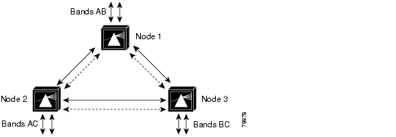
A meshed ring is a physical ring that has the logical characteristics of a mesh. While traffic travels on a physical ring, the logical connections between individual nodes are meshed. An example of this type of configuration, which is sometimes called a logical mesh, is shown in Figure 5-1.
Figure 5-1 Meshed Ring Topology Example
Verifying a Meshed Ring Configuration
This example procedure shows how to verify the path of each band in a meshed ring. You will test each band in both directions around the ring. Record test measurements in Table A-4 in "Node Data Checklist."
Note
Note
Step 1
Step 2
Step 3
Step 4
Switch# configure terminalSwitch(config)# interface wavepatch 2/0/0Switch(config-intf)# shutdownSwitch(config-intf)# interface wavepatch 2/0/1Switch(config-intf)# no shutdownOn node 2, also perform a shutdown command on the active interface, and a no shutdown command on the inactive interface. For example:
Switch# configure terminalSwitch(config)# interface wavepatch 2/0/0Switch(config-intf)# shutdownSwitch(config-intf)# interface wavepatch 2/0/1Switch(config-intf)# no shutdownStep 5
Step 6
Step 7
Step 8
Switch# configure terminalSwitch(config)# interface wavepatch 2/0/0Switch(config-intf)# shutdownSwitch(config-intf)# interface wavepatch 2/0/1Switch(config-intf)# no shutdownOn node 3, also perform a shutdown command on the active interface, and a no shutdown command on the inactive interface. For example:
Switch# configure terminalSwitch(config)# interface wavepatch 2/0/0Switch(config-intf)# shutdownSwitch(config-intf)# interface wavepatch 2/0/1Switch(config-intf)# no shutdownStep 9
Step 10
Step 11
Step 12
Switch# configure terminalSwitch(config)# interface wavepatch 2/0/0Switch(config-intf)# shutdownSwitch(config-intf)# interface wavepatch 2/0/1Switch(config-intf)# no shutdownOn node 1, also perform a shutdown command on the active interface, and a no shutdown command on the inactive interface. For example:
Switch# configure terminalSwitch(config)# interface wavepatch 2/0/0Switch(config-intf)# shutdownSwitch(config-intf)# interface wavepatch 2/0/1Switch(config-intf)# no shutdownStep 13
Step 14
Switch# show interfaces wave slot/subslot
Step 15
Step 16
If the results for a particular wavelength do not match, make sure fibers are fully inserted and transponder modules are inserted in the correct slots. Clean the fibers and connectors, and rerun the test.
If the results still do not match, there may be a hardware problem. On the Cisco ONS 15540 ESP, there may be a problem with the optical backplane. Remove the transponder module and install it in another slot, and rerun the test. Otherwise, there may be a problem with the transponder generating that wavelength.
Checking Connectivity between OSCs
Perform this procedure for each pair of neighbor nodes to check connectivity between OSCs.
Step 1
The following example shows how to display status information for the local and remote interfaces running OSCP.
Switch# show oscp interface wave 0Codes: Bndl - bundling identifier, Pri - OSCP selection priorityOSCP - dedicated wavelength channel, CDL - in-band wavelength channelOSCP Interface(s)Local Port Port ID Type Status OSCP St Bndl Pri Rem Port ID Rem Node Id~~~~~~~~~~~~~ ~~~~~~~ ~~~~ ~~~~~~ ~~~~~~~ ~~~~ ~~~ ~~~~~~~~~~~ ~~~~~~~~~~~~~~Wave0 1000000 OSCP Active 2way 0 0 1000000 0000.1644.28fbStep 2
If the status is not Active, the interface is not enabled. Perform a no shutdown command.
Switch# configure terminalSwitch(config)# interface wave 0Switch(config-intf)# no shutdownStep 3
Checking CDP Connectivity
Use the show cdp neighbors command to check whether the node can see other nodes in the topology.
Ping the node IP address.
Switch# show cdp neighborsCapability Codes: R - Router, T - Trans Bridge, B - Source Route BridgeS - Switch, H - Host, I - IGMP, r - RepeaterDevice ID Local Intrfce Holdtme Capability Platform Port IDman4 Wave1 127 R S ONS15540 Wave1man4 Wave0 127 R S ONS15540 Wave0Checking Power with an OSA
Perform this test to compare the measured power levels to the expected power levels given by a network design tool or by the result of a manual design power calculation. The measured power should be within an acceptable range from the expected power.
Use the wavelength spectrum application of an OSA to perform the following tests. Take measurements at several points in the ring.
Step 1
Step 2
Step 3
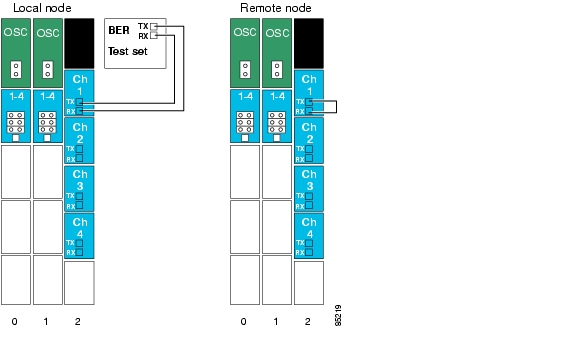
Testing the Bit Error Rate
Perform the following procedure to test bit error rate errors for each wavelength:
Step 1
Step 2
Figure 5-2 Testing Bit Error Rate
Step 3
Step 4
Step 5
Step 6
Step 7
Step 8
Step 9
Step 10
Step 11
![]()
![]()
![]()
![]()
![]()
![]()
![]()
![]()
Posted: Mon Dec 6 19:45:59 PST 2004
All contents are Copyright © 1992--2004 Cisco Systems, Inc. All rights reserved.
Important Notices and Privacy Statement.