|
|

Table Of Contents
Per Shelf Rules Using Add/Drop Mux/Demux Modules
Add/Drop Mux/Demux Modules with Splitter Protection
Add/Drop Mux/Demux Modules Without Splitter Protection
Transponder Module Placement When Using Add/Drop Mux/Demux Modules
Cabling of Add/Drop Mux/Demux Modules
Per Shelf Rules Using Terminal Mux/Demux Modules
Terminal Mux/Demux Modules with Splitter Protection
Terminal Mux/Demux Modules Without Splitter Protection
Transponder Module Placement When Using Terminal Mux/Demux Modules
Cabling of Terminal Mux/Demux Modules
Per Shelf Rules for 2.5-Gbps Line Card Motherboards
General Rules for Ring Topologies
Shelf Configuration Rules
The design of the Cisco ONS 15540 requires that a set of rules be followed during physical configuration of the shelf. These rules, along with examples, are provided in this chapter. This chapter contains the following major sections:
•
Per Shelf Rules Using Add/Drop Mux/Demux Modules
•
•
•
Note
Per Shelf Rules Using Add/Drop Mux/Demux Modules
In an unprotected configuration, a shelf can have only one add/drop mux/demux module with a given channel band transmitting and receiving in a given direction (either west or east). Table 3-1 lists the conflicting bands 4-channel and 8-channel add/drop mux/demux modules. If an add/drop mux/demux module that supports a band in a particular row of column 1 in Table 3-1 is installed on a shelf in an unprotected configuration, that shelf cannot also have a module that supports any of the conflicting bands in column 2 transmitting and receiving in the same direction. For example, modules for band A and band AB both cannot transmit to and receive from the west.
Add/Drop Mux/Demux Modules with Splitter Protection
When configuring channels to use splitter protection, add/drop mux/demux modules with the same channels must be present in the same positions in both slots 0 and 1. During migration, one of the modules might not be present, or one of the modules might contain only a subset of the channels present on the other module. The latter is only possible if the add/drop mux/demux modules map the common channels to the same optical backplane traces.
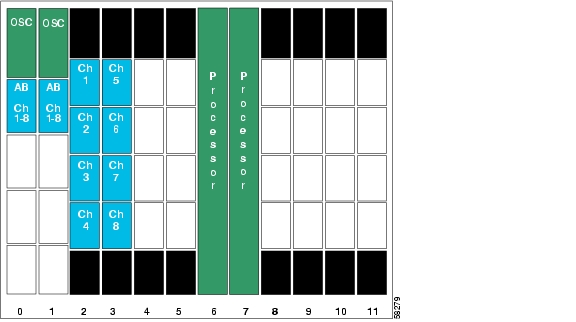
Figure 3-1 shows an example shelf configuration for splitter protection with add/drop mux/demux modules for band AB in positions 0/0 and 1/0.
Figure 3-1 Example Installation of Add/Drop Mux/Demux Modules with Splitter Protection
Add/Drop Mux/Demux Modules Without Splitter Protection
If not using splitter protection, when an add/drop mux/demux module is present in slot 0, there must be no mux/demux module in the corresponding position in slot 1 that picks up the same channels. Conversely, when an add/drop mux/demux module is present in slot 1, there must be no mux/demux module in the corresponding position in slot 0 that picks up the same channels.
Note
4-Channel Mux/Demux Modules Without Splitter Protection
The rules for the 4-channel mux/demux modules are as follows (see Table 3-2):
•
•
•
•
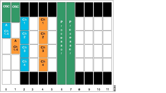
Figure 3-2 shows an example shelf configuration for line card protection with add/drop mux/demux modules for band A in positions 0/0 and 1/1.
Figure 3-2 Example Installation of Add/Drop Mux/Demux Modules with Line Card Protection
8-Channel Mux/Demux Modules Without Splitter Protection
The rules for 8-channel mux/demux modules are as follows:
•
•
Transponder Module Placement When Using Add/Drop Mux/Demux Modules
The fixed optical backplane maps the transponder (or ITU direct insertion module) subslots to connectors at specific positions on the mux/demux motherboards (see Figure 2-2). Thus, for all the channels present on the optical mux/demux modules, transponders must be present in the corresponding transponder subslots. Specifically, for all channels present on the add/drop mux/demux modules in positions 0/x or 1/x in Table 3-3, transponder modules should be present in slots y, y+1.
Table 3-3 Add/Drop Mux/Demux Module to Transponder Slot Mapping
0
2, 3
1
4, 5
2
8, 9
3
10, 11
For example, if there is an add/drop mux/demux module in position 0/2 or 1/2, you must use slots 8 and 9 for the transponder modules with the corresponding channels.
Note
Transponder Modules with 4-Channel Mux/Demux Modules
For the 4-channel mux/demux modules from group X in Table 3-2, transponder modules supporting channels w+0 to w+3 must be present in the positions shown in Table 3-4, where w is the first channel in the 4-channel band and y is the first transponder slot number in column 2 of Table 3-3.
Table 3-4 Transponder Module Placement for Lower Channels When Using 4-Channel Mux/Demux Modules
w+0
y/0
w+1
y/1
w+2
y/2
w+3
y/3
For example, if a band A module (channels 1-4) is present in mux/demux subslot 0, the four transponder modules supporting those channels must be installed in slot/subslots 2/0 through 2/3.
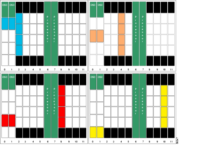
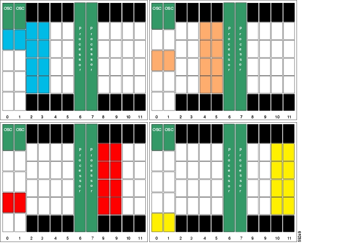
Figure 3-3 provides a graphic representation of the rule in Table 3-4. The figure shows the four possible arrangements of transponder modules and add/drop mux/demux modules that can support the lower 4 channels (bands A, C, E, G) of an 8-channel range. These examples assume splitter protection; if the east or west line card motherboard were used, one of the mux/demux slots would remain empty.
Figure 3-3 Transponder Placement with Add/Drop Mux/Demux Modules for Bands A, C, E, G
For the 4-channel mux/demux modules from group Y in Table 3-2, transponder modules supporting channels w+0 to w+3 must be present in the positions shown in Table 3-5, where w is the first channel in the 4-channel band and y+1 is the second transponder slot number in column 2 of Table 3-3.
Table 3-5 Transponder Module Placement for Upper Channels When Using 4-Channel Mux/Demux Modules
w+0
y+1/0
w+1
y+1/1
w+2
y+1/2
w+3
y+1/3
In other words, if you think of the 32 channels as comprising fou ranges of eight channels, you must install the transponder modules for the first four channels of a range of eight in either slot 2, 4, 8, or 10, and the transponder modules for the last four channels of the range in the next higher adjoining slot. The transponder modules must be installed in ascending order based on channel number.
For example, if a band B module (channels 5-8) is present in mux/demux subslot 0, the four transponder modules supporting those channels must be installed in slot/subslots 3/0 through 3/3.
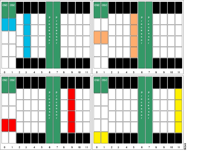
Figure 3-4 provides a graphic representation of the rule in Table 3-5. The figure shows the four possible arrangements of transponder modules and add/drop mux/demux modules that can support the upper 4 channels (bands B, D, F, and H) of an 8-channel range. These examples assume splitter protection; if the east or west line card motherboard were used, one of the mux/demux slots would remain empty.
Figure 3-4 Transponder Placement with Add/Drop Mux/Demux Modules for Bands B, D, F, H
Transponder Modules with 8-Channel Mux/Demux Modules
For 8-channel mux/demux modules containing channels w+0 to w+7, the transponder modules supporting these channels must be present in the positions shown in Table 3-6, where w is the first channel in an 8-channel band and y is the first transponder slot number in column 2 of Table 3-3.
Table 3-6 Transponder Module Placement When Using 8-Channel Mux/Demux Modules
w+0
y/0
w+1
y/1
w+2
y/2
w+3
y/3
w+4
y+1/0
w+5
y+1/1
w+6
y+1/2
w+7
y+1/3
For example, if a band AB module (channels 1-8) is present in mux/demux subslot 0, the four transponder modules supporting channels 1-4 must be installed in slot/subslots 2/0 through 2/3, and the four transponder modules supporting channels 5-8 must be installed in slot/subslots 3/0 through 3/3.
Figure 3-5 provides a graphic representation of the rule in Table 3-6. The figure shows the four possible arrangements of transponder modules and add/drop mux/demux modules that can support an 8-channel range (bands AB, CD, EF, GH). These examples assume splitter protection; if the east or west line card motherboard were used, one of the mux/demux slots would remain empty.
Figure 3-5 Transponder Placement with Add/Drop Mux/Demux Modules for Bands AB, CD, EF, GH
Cabling of Add/Drop Mux/Demux Modules
The following rules apply when cabling the 4- and 8-channel add/drop mux/demux modules:
•
•
•
•
•
•
For examples of add/drop mux/demux module cabling in a protected ring configuration, see Figure 1-1 on page 1-2 and Figure 1-6 on page 1-15.
Per Shelf Rules Using Terminal Mux/Demux Modules
There are two types of terminal (16-channel) mux/demux modules: one for band AD with OSC, and one for band EH without OSC. The band EH terminal mux/demux module can only be used in conjunction with the band AD module. The following sections describe additional rules for using the16-channel terminal mux/demux module.
Terminal Mux/Demux Modules with Splitter Protection
When using splitter protection, terminal mux/demux modules that support the same channels should be present in the same position in both slot 0 and slot 1. During migration, it is possible that a module will not be present in one of the slots, or that one of the modules contains a subset of the channels present on the other module. The latter is only possible if the terminal mux/demux modules map the common wavelengths to the same optical backplane traces.
Terminal Mux/Demux Modules Without Splitter Protection
When splitter protection is not used, if a terminal mux/demux module is present in slot 0, the corresponding position in slot 1 must be empty, and vice versa.
Transponder Module Placement When Using Terminal Mux/Demux Modules
For all the channels present on the terminal mux/demux modules in positions 0/x and 1/x, transponder modules should be present in the slots shown in Table 3-7.
Table 3-7 Terminal Mux/Demux Module to Transponder Slot Mapping
0-1
2, 3, 4, 5
2-3
8, 9, 10, 11
Note
Note
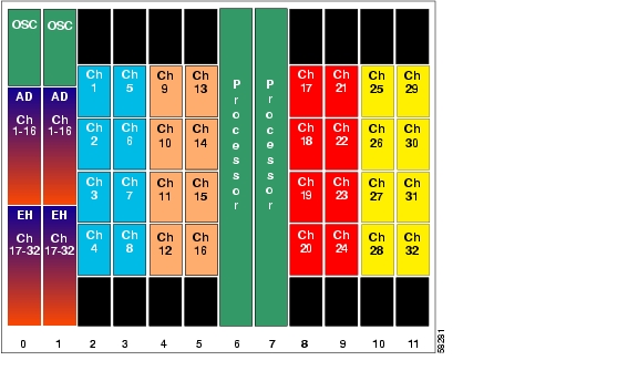
For the 16-channel mux/demux modules containing channels w+0 to w+15, transponder modules supporting these channels must be present in the positions shown in Table 3-8, where y is the first transponder slot number in column 2 of Table 3-7.
Note
Figure 3-6 provides a graphic representation of the rule in Table 3-8. The example shows a 32-channel splitter protected shelf configuration.
Figure 3-6 Transponder Module Placement Using 16-Channel Mux/Demux Modules for Bands AD and EH
Cabling of Terminal Mux/Demux Modules
The following rules apply when cabling the 16-channel terminal mux/demux modules:
•
•
•
Per Shelf Rules for 2.5-Gbps Line Card Motherboards
If splitter protection is used, the corresponding transponder slots must use the splitter protected line card motherboards.
If line card protection is used, the following rules apply:
•
•
Note
General Rules for Ring Topologies
The following network rules apply to ring topologies:
•
•
•
In addition, we recommend that if there are plans to migrate from a hubbed ring to a logical mesh, the 4-channel or 8-channel add/drop mux/demux modules should be considered for deployment at the terminal node. This strategy avoids the necessity of discarding a terminal mux/demux module when migrating.
![]()
![]()
![]()
![]()
![]()
![]()
![]()
![]()
Posted: Thu May 19 00:11:44 PDT 2005
All contents are Copyright © 1992--2005 Cisco Systems, Inc. All rights reserved.
Important Notices and Privacy Statement.