|
|

Table Of Contents
Line Card Motherboards and Transponder Modules
Mux/Demux Motherboards and Modules
Product Overview
The Cisco ONS 15540 ESP (Extended Services Platform) is an optical transport platform that employs DWDM (dense wavelength division multiplexing) technology. With the Cisco ONS 15540, users can take advantage of the availability of dark fiber to build a common infrastructure that supports data, SANs (storage area networks), and TDM (time-division multiplexing) traffic. For more information about DWDM technology and applications, refer to the Introduction to DWDM Technology and the Cisco ONS 15540 ESP Planning Guide.
This chapter describes the Cisco ONS 15540 and includes the following sections:
Note
Before you install, operate, or service the system, read the Regulatory Compliance and Safety Information for the Cisco ONS 15500 Series for important safety information you should know before working with the system.
Note
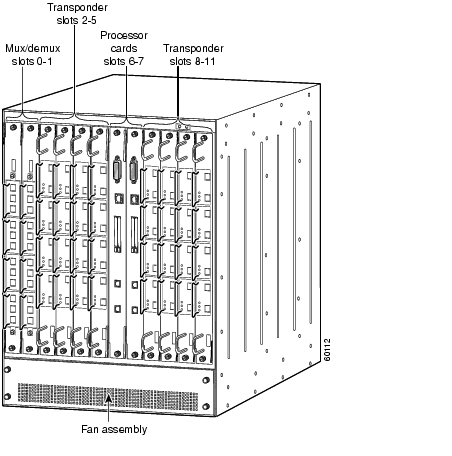
Cisco ONS 15540 Chassis
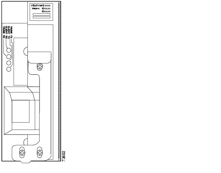
The Cisco ONS 15540 is a 12-slot modular vertical chassis. (See .) The system is powered by redundant -48 VDC inputs. A redundant external AC-input power supply is available or DC-input power can be provided directly. Slots 0 and 1 hold the optical mux/demux motherboards, which are populated with optical
Figure 1-1 Cisco ONS 15540 Shelf
mux/demux modules. Slots 2 to 5 and 8 to 11 hold the line card motherboards, which are populated with transponder modules. Slots 6 to 7 hold the processor cards.
The air intake and fan assembly are located beneath the modular slots. The system has an optical backplane for carrying signals between the transponders and the optical mux/demux modules and an electrical backplane for system control.
Fan Assembly
The Cisco ONS 15540 fan assembly is located at the bottom of the chassis and contains six individual fans and a fan controller board. The controller board monitors the status of each fan and reports the status to the CPU switch modules. If a single fan fails, a minor alarm is reported to the processor card. If two or more fans fail, a major alarm is reported to the processor card. To prevent damage to the cards and modules in the shelf when two or more fans fail, you can configure the system to automatically reset or power off the transponder modules. The transponder modules power off if the hardware version of the line card motherboard is 5.1 or later, otherwise the transponder modules reset. Use the show hardware command to determine the hardware version of the 2.5-Gbps line card motherboards.
To recover from fan failure shutdown, you must power-cycle the shelf.
Note
Caution
Fan status is reported to the processor cards. Table 2-2 lists the LEDs describing the alarm reports for the fan assembly.
Power Supplies
The external power supply is a single-phase, AC-DC, 1050W, -48V output power supply that connects to the chassis through terminal blocks. The external power supply is installed in an external power shelf that fits into a standard equipment rack. Up to three external power supplies can be installed in the external power shelf.
When the chassis is used in the telco environment, DC-input power is directly powered to the chassis through the terminal blocks. See the "Powering Up the Shelf" section for more information about the power supplies.
Backplane
The Cisco ONS 15540 optical backplane has no active components and uses a cable of single mode fibers. The power connectors on the modules connect to the electrical backplane allowing modules to draw up to 100W of power. The backplane used on the chassis provides the optical connections between the line card motherboards and their attached transponder modules on the client side and the mux/demux motherboards and modules on the trunk side.
Refer to the Cisco ONS 15540 ESP Planning and Design Guide for more information about the optical backplane and slot mapping.
The alarm signals from the processor card are sent to the alarm card attached to the bottom of the backplane. They connect to the central office alarm via connectors on the backplane. For information about alarm cable connections, see the "Installing Strain Relief Brackets" section.
Alarm Cards
The alarm card has relays and terminal blocks to interface the chassis to the Telco Central Office alarm equipment. It is a separate card that mounts to the back of the chassis and connects to the backplane.
There are six relays on the alarm card. They are audible and visible with three levels for each type:
•
•
•
Each relay has two form C contacts. One is used to connect to the terminal block and the outside. The other is used to provide feedback on the state of the relay.
A processor card energizes the relays by driving 3.3 volts to them. Only the primary processor card drives the relays, however, each processor card can tell if the relay is energized by sensing that the feedback line is grounded through the second contact.
Table 1-1 lists the specifications for the alarm cards on the Cisco ONS 15540 ESP.
Table 1-1 Alarm Card Specifications
P1
Visible
Minor
1
C1
Each type and level of alarm is signaled by a contact closure of C to NO and an open from C to NC.
Voltage at contacts is limited to 48 VDC.
Switched current / load is limited to 1 A resistive.
Alarms are signaled when the chassis is unpowered.
2
NC2
3
NO3
Major
4
C
5
NC
6
NO
Critical
7
C
8
NC
9
NO
P2
Audible
Minor
1
C
2
NC
3
NO
Major
4
C
5
NC
6
NO
Critical
7
C
8
NC
9
NO
1 C = center
2 NC = normally closed
3 NO = normally open
Cisco ONS 15540 Components
The following hardware components can be installed in the Cisco ONS 15540:
•
•
•
•
Line Card Motherboards and Transponder Modules
You can install up to eight hot-swappable line card motherboards in slots 2 to 5 and 8 to 11 of the Cisco ONS 15540 chassis. Each line card motherboard holds up to four transponder modules that have a single protocol-transparent and bit-rate transparent external interface to the client side network and an internal interface that connects over the system's backplane to the mux/demux modules. The transponder modules are hot pluggable, allowing in-service upgrades and replacement.
Line Card Motherboards
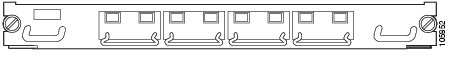
Line card motherboards are available with or without splitter protection. (See Figure 1-2.)
Figure 1-2 Line Card Motherboard with Four Transponder Modules
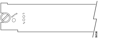
Line Card Motherboard LEDs
Table 1-2 lists the LEDs on the 2.5-Gbps line card motherboard faceplate, their default conditions, and what the conditions indicate. Figure 1-3 shows the 2.5-Gbps line card motherboard without inserts installed.
Figure 1-3 2.5-Gbps Line Card Motherboard
Transponder Modules
In the transponder module, the client signal is converted to an ITU-compliant wavelength, which is crossconnected over the optical backplane to the mux/demux modules. You can populate the line card motherboard subcard slots with as few or as many transponder modules as required (up to 32) to support the desired number of client signals, or data channels.
The Cisco ONS 15540 supports five types of single interface transponder modules:
•
•
•
SM Transponder Modules
SM transponder modules have fixed, non-pluggable transceivers for the single client interface. SM transponder modules accept SM client signals on the 1310-nm wavelength through an SC connector and support client signal clock rates ranging from 16 Mbps to 2.5 Gbps.
MM Transponder Modules
MM transponder modules have fixed, non-pluggable transceivers for the single client interface. MM transponder modules accept both SM client signals and MM client signals on the 1310-nm wavelength through an SC connector and support client signal clock rates ranging from 16 Mbps to 622 Mbps.
Type 2 Extended Range Transponder Modules with SFP Optics
The Type 2 extended range transponder modules accepts two types of SFP optics, fixed rate and variable rate. (See Figure 1-4.)
Figure 1-4 Type 2 Extended Range Transponder Module
Fixed rate SFP optics modules support specific protocols. Table 1-3 lists the features for the fixed rate SFP optics supported by the Type 2 extended range transponder modules.
Note
Table 1-3 Fixed Rate SFP Optics Features
15500-XVRA-01A2
ESCON, SONET OC-3 SR, SDH STM-1
MM 50/125 Βm
MM 62.5/125 Βm1310 nm
MT-RJ
15500-XVRA-02C1
Gigabit Ethernet1 ,
Fibre Channel (1 Gbps)2 , FICON (1 Gbps), ISC-1 (1-Gbps)MM 50/125 Βm
MM 62.5/125 Βm850 nm
LC
15500-XVRA-02C2
Fibre Channel (1 Gbps and 2 Gbps)3 , FICON (1 Gbps and 2 Gbps), ISC-3 (1-Gbps and 2-Gbps)
MM 50/125 Βm
MM 62.5/125 Βm850 nm
LC
15500-XVRA-03B1
Gigabit Ethernet4 ,
Fibre Channel (1 Gbps)5 ,
FICON (1 Gbps), ISC compatibility mode (1 Gbps), ISC peer mode (1 Gbps)SM 9/125 Βm
1310 nm
LC
15500-XVRA-03B2
Fibre Channel (1 Gbps6 and 2 Gbps7 ), FICON (1 Gbps and 2 Gbps), ISC compatibility mode (1 Gbps), ISC peer mode (1 Gbps and 2 Gbps)
SM 9/125 Βm
1310 nm
LC
15500-XVRA-06B1
SONET OC-12 SR8 , SDH STM-4
SM 9/125 Βm
1310 nm
LC
15500-XVRA-07B1
SONET OC-48 SR, SDH STM-16
SM 9/125 Βm
1310 nm
LC
1 1000BASE-SX
2 FC-0-100-M5-SN-S and FC-0-100-M6-SN-S standards
3 FC-0-200-M5-SN-S and FC-0-200-M6-SN-S standards
4 1000BASE-LX
5 FC-0-100-SM-LC-S standard
6 FC-0-100-SM-LC-S standard
7 FC-0-200-SM-LC-S standard
8 SR = short range
Variable rate SFP optics modules support a range of clock rates. Table 1-4 list the characteristics for the variable rate SFP optics supported by the Type 2 extended range transponder.
Table 1-4 Variable Rate SFP Optics Features
15500-XVRA-10A1
Low-band 8 Mbps to 200 Mbps
Sysplex (CLO and ETR)1 (8 Mbps),
Fast Ethernet2 (125 Mbps),
SONET OC-33 (155.52 Mbps),
SDH STM-1 (622 Mbps),
ESCON4 (200 Mbps)MM 50/125 Βm 62.5/125 Βm
1310 nm
LC
15500-XVRA-10B1
Low-band 8 Mbps to 200 Mbps
Sysplex (CLO and ETR)1 (8 Mbps),
Fast Ethernet2 (125 Mbps),
SONET OC-33 (155.52 Mbps),
SDH STM-1 (155.52 Mbps), ESCON4 (200 Mbps)SM 9/125 Βm
1310 nm
LC
15500-XVRA-11A1
Mid-band 200 Mbps to 622 Mbps
ESCON4 (200 Mbps),
SONET OC-123 (622 Mbps),
SDH STM-4 (622 Mbps)MM 50/125 Βm 62.5/125 Βm
1310 nm
LC
15500-XVRA-11B1
Mid-band 200 Mbps to 1.25 Gbps
ESCON4 (200 Mbps),
SONET OC-123 (622 Mbps),
SDH STM-4 (622 Mbps),
FC4 (1.062 Gbps),
FICON (1.062 Gbps),
GE4 (LX) (1.250 Gbps)
ISC compatibility mode (1.062 Gbps),
ISC peer mode (1.062 Gbps)SM 9/125 Βm
1310 nm
LC
15500-XVRA-12B1
High-band 1.062 Gbps to 2.488 Gbps
FC4 (1.062 Gbps and 2.125 Gbps),
FICON (1.062 Gbps and 2.125 Gbps),
GE4 (LX) (1.250 Mbps),
SONET OC-48 (2.488 Gbps),
SDH STM-16 (2.488 Gbps),
ISC compatibility mode (1.062 Gbps),
ISC peer mode (1.062 Gbps and 2.125 Gbps)SM 9/125 Βm
1310 nm
LC
1 Manchester coded
2 4B/5B coded
3 Scrambler 223-1
4 8B/10B coded
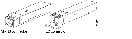
Figure 1-5 shows the two types of SFP optics that the Type 2 extended range transponders support.
Note
Figure 1-5 Type 2 Extended Range Transponder Module SFP Optics
For information on how to install the SFP optics onto the transponder module, see the "Installing the Type 2 Extended Range Transponder Modules with SFP Optics" section.
Transponder Module LEDs
Table 1-5 lists the LEDs on the transponder module faceplate, their default conditions, and what the conditions indicate. (See Figure 1-6.)
Figure 1-6 SM and MM Transponder Module LEDs
Table 1-6 lists the LEDs for the Type 2 extended range transponder module. Figure 1-7 shows the LEDs.
Figure 1-7 Type 2 Extended Range Transponder Module LEDs
Y-Cables
Y-cables are 2:1 combiner cables used for splitter protection on the transponder modules. Using a y-cable enables full protection on the Cisco ONS 15540 and offers protection against both facility failures and transponder card failures.
For detailed information about the hardware rules, refer to the Cisco ONS 15540 ESP Planning Guide. To attach y-cables to your system, see the "Powering Up the Shelf" section.
Mux/Demux Motherboards and Modules
The optical mux/demux motherboards occupy slots 0 and 1 of the Cisco ONS 15540 chassis. The chassis uses one optical mux/demux motherboard for unprotected operation or two per system for protected operation. Each mux/demux motherboard can accept up to four mux/demux modules. The modular mux/demux motherboards are available with or without OSC (optical supervisory channel) and can be populated according to user needs. There are three types of mux/demux modules available:
•
•
•
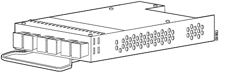
Up to four 4-channel or 8-channel optical add/drop mux/demux modules can be installed in a mux/demux motherboard. Each module can multiplex and demultiplex a band of 4 or 8 channels, for a maximum of 32 channels. Channels not filtered are passed on to the next mux/demux module. The add/drop mux/demux modules connect to the trunk side and to the transponder modules over the optical backplane. (See Figure 1-8.)
Figure 1-8 Mux/Demux Module with OSC
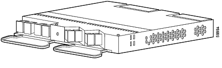
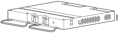
Two 16-channel optical terminal mux/demux modules can be installed in a mux/demux motherboard. Each terminal mux/demux module can multiplex and demultiplex a band of 16 channels, for a maximum of 32 channels. All of the channels received by the module are terminated, none are passed through. The terminal mux/demux modules connect to the trunk side and to the transponder modules over the backplane. (See Figure 1-9 and Figure 1-10.)
Figure 1-9 16-Channel Terminal Mux/Demux Module with OSC
Figure 1-10 16-Channel Terminal Mux/Demux Module without OSC
Note
Mux/Demux Motherboard LEDs
Table 1-7 lists the LEDs on the mux/demux motherboard with OSC faceplate, their default conditions and what the conditions indicate. (See Figure 1-11.)
Note
Figure 1-11 Mux/Demux Motherboard with OSC LEDs
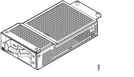
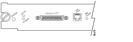
Processor Cards
Slots 6 and 7 of the Cisco ONS 15540 chassis hold processor cards. The processor cards support redundancy and online insertion and removal. In a redundant system, the processor cards monitor each other using the Ethernet backplane and signals. The processor card monitors the fan assembly operation and airflow temperature. (See Figure 1-12.) During a fan failure or an out-of-temperature range condition, the processor card activates an alarm. See Table 2-2 for fan assembly status.
Figure 1-12 Processor Card
Processor cards manage communication functions for the system. The cards monitor all modules in the chassis and determine the state of the system. Each module determines its state from feedback at various system monitoring points. The processor generates clocking to all the modules and some additional components in the system.
Processor Card LEDs
Table 1-8 lists the LEDs on the processor card faceplate, their default conditions, and what the conditions indicate. Figure 1-13 and Figure 1-14 show the processor card LEDs.
Table 1-8 Processor Card LEDs
Status
Red
A board reset or initial power on.
Orange
System initialization.
Green
Full initialization and operational.
Active
Green
This board is the primary processor and is running IOS software.
Standby
Green
This board is the secondary processor.
Slot 0
Green
Flash PC Card is present.
Slot 1
Green
Flash PC Card is present.
NME
Full Duplex
Green
Full duplex is running.
Off
Half duplex is running.
100 Mbps
Green
Operating at 100 Mbps.
Off
Operating at 10 Mbps.
Link
Green
Link is up.
Off
Link is down.
ASE
Full Duplex
Green
Full duplex is running.
Off
Half duplex is running.
100 Mbps
Green
Operating at 100 Mbps.
Off
Operating at 10 Mbps.
Link
Green
Link is up.
Off
Link is down.
Critical alarm
Yellow
A critical alarm condition exists.
Major alarm
Yellow
A major alarm condition exists.
Minor alarm
Yellow
A minor alarm condition exists.
Alarm cutoff
Yellow
A major or minor alarm condition exists and the cutoff button has been pushed. Turns off by software when the original alarm clears or any new alarm occurs. See Table 1-11.
History
Yellow
A major or minor alarm occurred. Clears if the Clear button is pushed and no alarm exists. See Table 1-11.
Figure 1-13 Processor Card LEDs (Left Side)
Figure 1-14 Processor Card LEDs (Right Side)
Note
Management Ports
The console port is a female data communications equipment (DCE), DB-25 receptacle used for connection to a console terminal or modem. Table 1-9 lists the console port pinouts.
The auxiliary port is a female RJ-45 receptacle used for connection to a modem. A three inch RJ-45 cable ships with the processor card for use with the auxiliary port. This cable is necessary for proper use of the auxiliary port. Attach this cable to the auxiliary port before attaching your own cables to it using the proper coupler. See Table 1-10 for the auxiliary port pinouts on the processor card.
Alarms
The processor generates three alarm signals: critical, major, and minor. (See Table 1-8.) These signals from the alarm card generate visual and audible alarm signals to the backplane. The alarm card is a separate card that mounts on the back of the chassis to the backplane. The alarm card has relays and terminal blocks to interface the system to the telco central office alarms. LEDs on the processor card front panel display the status of the critical, major, and minor alarm signals, plus the status of alarm cutoff (ACO) and history conditions.
Push button switches on the front panel provide for the alarm cutoff and history clear functions. (See Table 1-11.)
Note
Flash SIMM
The processor card Flash SIMM is a 16 MB, 80-pin SIMM that contains a compressed Cisco IOS image that is loaded and executed automatically by ROMMON upon powerup.
Flash PC Card Slots
The processor card has two Flash PC Card slots that are accessible from the front panel. Either slot can be a memory or an I/O device.
The Flash PC Cards are typically used to copy system images and save standard configurations. Flash PC Cards are a type of Flash memory that provide expanded file storage for your system. Flash PC Cards, unlike the onboard Flash SIMM (bootflash), are not required for the operation of the system.
Note
Table 1-12 lists the Flash PC Card slot LEDs on the processor faceplate and what the conditions indicate.
Table 1-12 Flash PC Card Slot LEDs
Slot 0
Green
Flash PC Card slot 0 is being accessed.
Slot 1
Green
Flash PC Card slot 1 is being accessed.
NMI Clear
A recessed push button, labeled NMI CLR, is accessible through the faceplate to clear an NMI (non-maskable interrupt).
Note
NME Interface
The NME (network management Ethernet) interface supports 10-Mbps or 100-Mbps UTP (unshielded twisted-pair) ports. This RJ-45 interface supports full-duplex or half-duplex connections.
The NME port on the processor card is a management port that allows multiple simultaneous Telnet or SNMP network management sessions. The Ethernet port on the processor card does not route or bridge traffic to other Ethernet ports on the Cisco ONS 15540. This Ethernet port is a management port only and cannot be configured as a routing port.
Table 1-13 describes the LEDs used to confirm and troubleshoot the operation of the NME interface. The LEDs on the processor faceplate indicate the status of the NME interface.
Blank Panels
You can install blank panels in any of the 12 slots of the Cisco ONS 15540 ESP chassis or in the line card motherboards and mux/demux motherboards. Blank panels have connectors that protect the backplane from dust and particles and are also required for proper airflow in the chassis.
The blank panels are specific to what slot you use them in. They are available as follows:
•
•
•
•
![]()
![]()
![]()
![]()
![]()
![]()
![]()
![]()
Posted: Thu Feb 17 08:43:44 PST 2005
All contents are Copyright © 1992--2005 Cisco Systems, Inc. All rights reserved.
Important Notices and Privacy Statement.