|
|

Table Of Contents
Installing the Cisco ONS 15540
Unpacking and Inspecting the Shelf
Installing Strain Relief Brackets
Installing and Removing Motherboards and Processor Cards
Installing Mux/Demux Motherboards and Processor Cards
Removing Mux/Demux Motherboards and Processor Cards
Installing Line Card Motherboards
Removing Line Card Motherboards
Installing and Removing Modules
Installing 16-Channel Mux/Demux Modules
Installing Mux/Demux and 2.5 Gbps Transponder Modules
Installing the Type 2 Extended Range Transponder Modules with SFP Optics
Removing SFP Optics from the Type 2 Extended Range Transponders
Using CLI Prior to 2.5-Gbps Transponder Module Removal
Installing and Removing the Fan Assembly
Rack-Mounting the 15540-PWR-AC External Power Shelf
Rack-Mounting the 15540-ACPS-N-E External Power Shelf
Installing the Cisco ONS 15540
This chapter describes the installation procedures for the Cisco ONS 15540 chassis and its components. This chapter includes the following sections:
•
Installing Strain Relief Brackets
•
•
•
Note
Note
Warning
Before Installing
Before you install the shelf, you must complete the following tasks:
•
•
•
Caution
Unpacking and Inspecting the Shelf
The Cisco ONS 15540 shelf comes with the standard mounting set. The shelf is thoroughly inspected before shipment. If any damage has occurred during transportation or if any item is missing, notify your Cisco customer service representative immediately.
Upon receipt, inspect the equipment as follows:
Step 1
Compare the equipment inside with the packing slip and the equipment list provided by customer service. If there are any discrepancies, notify the Customer Service Center.
Step 2
Visually check all components and immediately report any shipping damage to your customer service representative. Have the following information ready:
•
•
•
•
Maintaining a Network Record
Fill out the information in Appendix B, "Maintenance and Network Records," so you will have a record of all of your hardware, configuration options, and network settings.
Mounting the Shelf
The unit is designed for rack-mounting in a cabinet rack. Use star-type lock washers on the rack screws to ensure a good conductive connection between the chassis and the rack. For information about installing the units in a customer cabinet, see the instructions from the cabinet manufacturer.
Note
Rack-Mounting the Shelf
You can install the Cisco ONS 15540 ESP chassis in a standard 19-inch rack, a 21-inch rack, or a 23-inch rack. Table 2-1 lists the correct L bracket part number required for each installation.
Table 2-1 L Bracket Part Numbers
19-inch
700-15196-01
21-inch
700-15176-01
23-inch
700-18074-01
Three chassis fit in a standard rack. However, if you use the external AC-input power supply, you can install two chassis with the power supply.
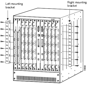
To rack-mount the shelf, follow these steps:
Step 1
Step 2
Figure 2-1 Attaching L Brackets
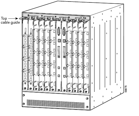
Step 3
Figure 2-2 Cable Guide on the Shelf
Step 4
Tip
Installing the Shelf
Warning
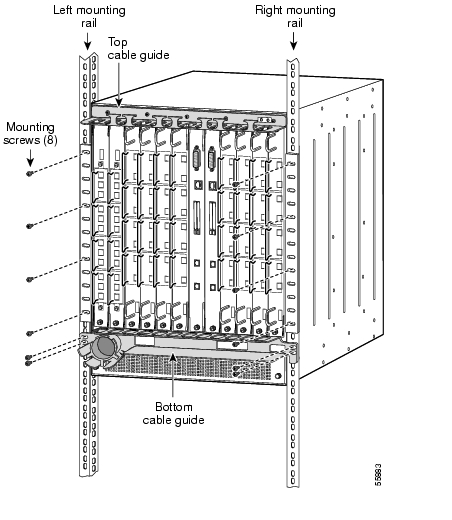
To install the chassis in the rack, follow these steps:
Step 1
Step 2
Step 3
Step 4
Step 5
Step 6
Figure 2-3 Installing the Shelf in the Rack
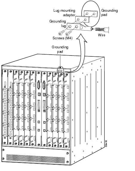
Grounding the Shelf
Two system (earth) grounding holes are provided in an enclosure near the top of the chassis.
Shelf Grounding Guidelines
To make an adequate grounding connection, you need the following parts and tools:
•
•
•
•
•
•
•
Note
Shelf Grounding Procedures
This section describes how to connect the Cisco ONS 15540 to earth ground. You must complete this procedure before connecting system power or powering up your shelf.
Tip
To ground the shelf, follow these steps:
Step 1
Step 2
Step 3
Step 4
Step 5
Note
Step 6
Step 7
Step 8
Step 9
Step 10
Cisco ONS 15540.Figure 2-4 Grounding Receptacle
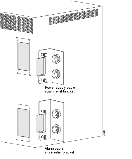
Installing Strain Relief Brackets
The Cisco ONS 15540 system uses a power supply cable strain relief bracket for connections to its power supply and an alarm cable strain relief bracket for alarm cable connections. The strain relief brackets must be installed after the shelf is rack mounted and installed in the rack. The brackets are required for proper function of the power supply and alarm cables.
To install the strain relief brackets, follow these steps:
Step 1
Step 2
Figure 2-5 Cable Strain Relief Brackets
To power the system, see the "Powering Up the Shelf" section.
Installing and Removing Motherboards and Processor Cards
The mux/demux motherboards, line card motherboards, and processor cards are hot-swappable. This section describes the procedures for installing and removing the motherboards and processor cards from the chassis.
Installing Mux/Demux Motherboards and Processor Cards
To install a mux/demux motherboard or processor card, follow these steps:
Step 1
Step 2
Step 3
Step 4
Step 5
Step 6
Save the filler motherboards with the packaging material.
Removing Mux/Demux Motherboards and Processor Cards
To remove the mux/demux motherboards and processor cards, follow these steps:
Step 1
Step 2
Step 3
Step 4
Place the removed motherboard or processor card in a container appropriate for shipping and storage. To install a replacement motherboard or processor card, see the "Installing Mux/Demux Motherboards and Processor Cards" section.
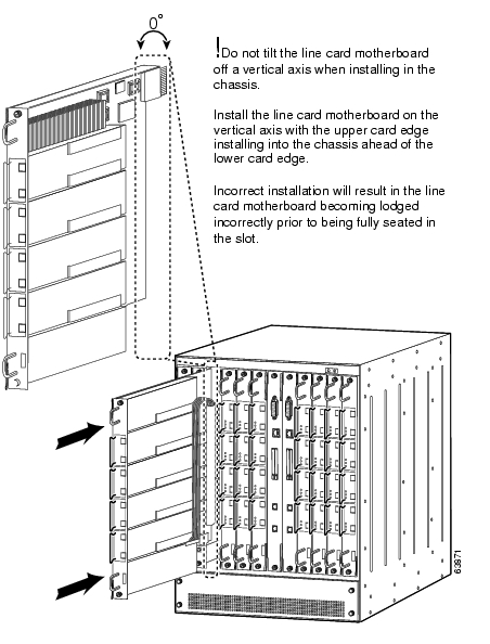
Installing Line Card Motherboards
To install a line card motherboard, follow these steps:
Step 1
Step 2
Step 3
Figure 2-6 Installing a Line Card Motherboard
Step 4
Step 5
Step 6
Removing Line Card Motherboards
To remove the line card motherboards, follow these steps:
Step 1
Step 2
Step 3
Step 4
Place the removed line card motherboard in a container appropriate for shipping and storage. To install a replacement line card motherboard, see the "Installing Line Card Motherboards" section.
Installing and Removing Modules
The mux/demux modules and transponder modules are hot-swappable. This section describes the procedure for installing and removing modules from the motherboards.
Warning
Installing Modules
This section describes how to install mux/demux and transponder modules. If you are installing a 16-channel mux/demux module, see the "Installing 16-Channel Mux/Demux Modules" section. If you are installing an Type 2 extended range transponder with selectable transceivers, see the "Installing the Type 2 Extended Range Transponder Modules with SFP Optics" section.
To install the mux/demux modules or transponder modules, follow these steps:
Step 1
Step 2
Step 3
Note
Step 4
Note
Step 5
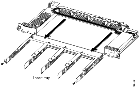
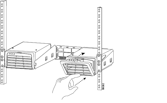
Installing 16-Channel Mux/Demux Modules
This section describes the procedure for replacing 4-channel or 8-channel mux/demux modules with 16-channel terminal mux/demux modules.
To install the 16-channel terminal mux/demux module, follow these steps:
Step 1
Step 2
Step 3
Figure 2-7 Removing the Insert Tray
Step 4
Step 5
Step 6
Note
Step 7
Step 8
Step 9
Installing Mux/Demux and 2.5 Gbps Transponder Modules
To install the mux/demux modules or 2.5 transponder modules follow these steps:
Step 1
Step 2
Step 3
Step 4
Save the filler modules with the packaging material.
Installing the Type 2 Extended Range Transponder Modules with SFP Optics
Note
To install the Type 2 extended range transponders with SFP optics, follow these steps:
Step 1
Step 2
Step 3
Step 4
Step 5
Removing SFP Optics from the Type 2 Extended Range Transponders
There are two types of SFP optics that can be installed in the extended reach transponder modules. The connectors on the SFP optics are:
•
•
The MT-RJ connector is typically used for lower rate connections (ESCON and OC-3). The LC connector is typically used for higher rate connections (Gigabit Ethernet and Fibre Channel). Each connector requires a different method of removal. Each type of SFP requires a different method of removal.
Note
Removing SFP Optics with MT-RJ Connectors
Note
To remove an SFP with an MT-RJ connector from the extended reach transponder module, follow these steps:
Step 1
Step 2
Figure 2-8 Removing the SFP with MT-RJ Connector
SFP placement in the module
Hole where the SFP extraction end of the tool is inserted
Lever on the SFP (two views)
SFP extraction and cable installation and removal tool
Step 3
Step 4
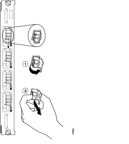
Removing SFP Optics with LC Connectors
To remove an SFP with an LC connector from the extended reach transponder module, follow these steps:
Step 1
Step 2
Figure 2-9 Removing the SFP with the LC Connector
Step 3
Step 4
Using CLI Prior to 2.5-Gbps Transponder Module Removal
Removing a 2.5-Gbps transponder module from the Cisco ONS 15540 ESP causes bit rate errors on other transponder modules in the 2.5-Gbps line card motherboard. Although these errors do not affect system traffic, you can avoid them using the following privileged EXEC command before removing the transponder module:
hw-module subslot slot/subslot power off
Turns off the power to a 2.5-Gbps transponder module.
Note
To determine the functional image and hardware versions on your system, use the show hardware detail command.
Note
Example
The following example shows how to turn off the power to a 2.5-Gbps transponder module before removing it:
Switch# hw-module subslot 8/1 power offWarning: Power OFF subcard 8/1. Continue? [confirm]ySwitch#Verifying 2.5-Gbps Transponder Module Power Status
To verify the status of the power to a 2.5-Gbps transponder module, use the following privileged EXEC command:
show hardware linecard slot
Displays hardware information for a specific slot in the shelf.
Example
The following example shows how to display the power status of the subcards in a 2.5-Gbps line card motherboard:
Switch# show hardware linecard 8-------------------------------------------------------------------Slot Number : 8/*Controller Type : XpndrMotherboardOn-Board Description : TRANSPONDER_MOTHER_PHASE_0Orderable Product Number: N/ABoard Part Number : 73-5813-05Board Revision : 05Serial Number : CAB0517HLRVManufacturing Date : 03/30/2001Hardware Version : 5.1RMA Number : 0x00RMA Failure Code : 0x00Functional Image Version: 2.55Subcard Power Control : 0:ON, 1:OFF, 2:ON, 3:ON<Information deleted.>Removing Modules
Warning
Note
To remove a module from your unit without interrupting system operation, follow these steps:
Step 1
Step 2
Step 3
Step 4
Installing and Removing the Fan Assembly
The fan assembly is hot-swappable. Fan status is reported to the processor cards. Table 2-2 lists the status for the fan assembly. If a major alarm occurs, the fan assembly should be replaced.
Note
To replace the fan assembly in the Cisco ONS 15540, follow these steps:
Step 1
Step 2
Step 3
Step 4
Step 5
Step 6
Step 7
Step 8
Step 9
Powering Up the Shelf
The system is powered by redundant -48 VDC inputs. Two models (15540-PWR-AC and 15540-ACPS-N-E) of redundant external AC-input power supplies are available or DC-input power can be provided directly.
The external power supplies are single-phase, AC-DC, 1050 W, -48 V output power supplies. The external power supplies are installed in an external power shelf that fits into a standard equipment rack. The following note and warnings apply to direct DC-connected installations.
Note
Warning
Warning
If an external AC-input power supply is not used, proceed to the "Connecting DC-Input Power from the 15540-PWR-AC Power Supply" section.
Rack-Mounting the 15540-PWR-AC External Power Shelf
The external power shelf is available in two models. This section describes the installation of the 15540-PWR-AC external power shelf. See the "Rack-Mounting the 15540-ACPS-N-E External Power Shelf" section for the other model.
Note
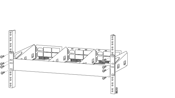
To install the 15540-PWR-AC external power shelf in an equipment rack, follow these steps:
Step 1
Step 2
Figure 2-10 Installing the 15540-PWR-AC External Power Shelf in the Rack
Step 3
Installing and Connecting the 15540-PWR-AC External Power Supply
After you have installed the 15540-PWR-AC external power shelf in the equipment rack, you can install the 15540-PWR-AC power supplies. If you have not installed the 15540-PWR-AC external power shelf, see the "Rack-Mounting the 15540-PWR-AC External Power Shelf" section.
To install a 15540-PWR-AC power supply, follow these steps:
Step 1
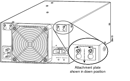
Step 2
Figure 2-11 Sliding the External Power Supply Attachment Plates Down
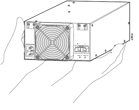
Step 3
Figure 2-12 Handling the 15540-PWR-AC Power Supply
Caution
Step 4
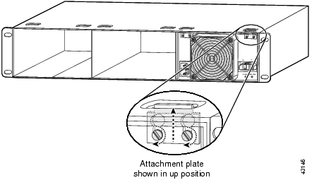
Step 5
Figure 2-13 Tightening the Attachment Plates
Step 6
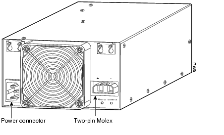
Step 7
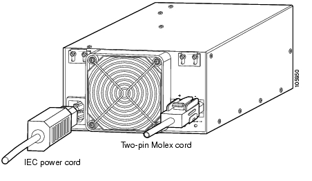
Figure 2-14 Power Connector and Two-Pin Molex Connector
Step 8
Step 9
Figure 2-15 Connecting the 15540-PWR-AC Power Supply to the Chassis
Caution
Step 10
•
•
Step 11
Connecting DC-Input Power from the 15540-PWR-AC Power Supply
To apply DC-input power to your Cisco ONS 15540 shelf, follow these steps:
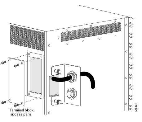
Step 1
Figure 2-16 Removing the Terminal Block Access Panel
Step 2
Step 3
Figure 2-17 Inserting the Cord Through the Power Supply Cable Strain Relief
Step 4
•
•
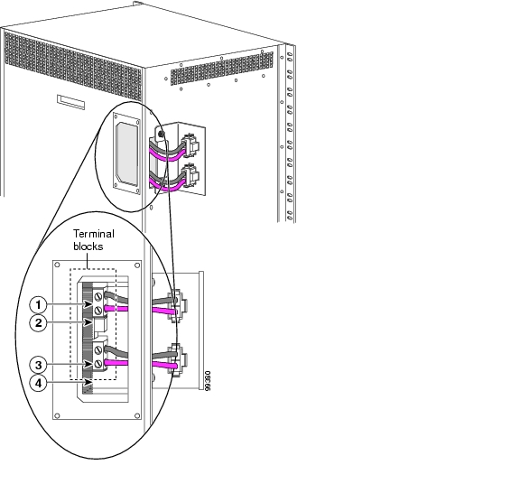
Note
Note
Figure 2-18 Connecting Cable Wires to the Terminal Blocks
Step 5
Figure 2-19 Reinstalling the Terminal Block Access Panel
Step 6
Rack-Mounting the 15540-ACPS-N-E External Power Shelf
This section describes the installation of the 15540-ACPS-N-E external power shelf.
Note
To install the 15540-ACPS-N-E external power shelf in an equipment rack, follow these steps:
Step 1
Step 2
Figure 2-20 Installing the 15540-ACPS-N-E External Power Shelf in the Rack
Step 3
Step 4
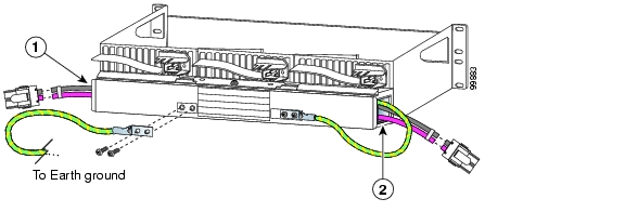
Connecting DC-Input Power from the 15540-ACPS-N-E External Power Shelf
To apply DC-input power to your Cisco ONS 15540 shelf, you must install a cable strain relief bracket and two DC power cables. The two DC power cables are connected to each other at the cable strain relief bracket. To complete the connections, follow these steps:
Step 1
Figure 2-21 Installing the Cable Strain Relief Bracket
Step 2
Figure 2-22 Removing the Terminal Block Access Panel
Step 3
Step 4
•
•
Note
Figure 2-23 Connecting Cable Wires to the Terminal Blocks
Step 5
•
•
Step 6
Step 7
Figure 2-24 Connecting to Earth Ground
Step 8
Step 9
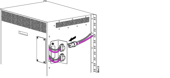
Figure 2-25 Connecting the DC Power Cables
Installing and Connecting the 15540-ACPS-N-E External Power Supply
After you have installed the 15540-ACPS-N-E external power shelf in the equipment rack, you can install the external power supplies. If you have not installed the external power shelf, see the "Rack-Mounting the 15540-ACPS-N-E External Power Shelf" section.
To install the 15540-ACPS-N-E power supply, follow these steps:
Step 1
Figure 2-26 Opening the Release Handle
Step 2
Figure 2-27 Handling the 15540-ACPS-N-E Power Supply
Caution
Step 3
Note
Figure 2-28 Installing the 15540-ACPS-N-E Power Supply
Step 4
Caution
Step 5
Figure 2-29 Installing the AC Power Cord
Step 6
•
•
Step 7
Using Y-Cable
Using an external 2:1 combiner (the y-cable), connections between the client equipment and the transponder interfaces are duplicated. This means each input and output client signal is connected to two transponder interfaces, one active and one standby. During any interval, one of the transmitters at the client interface is turned on and is generating the required optical signal, and the second transmitter is off.
Refer to the Cisco ONS 15540 ESP Planning Guide for y-cable configuration guidelines.
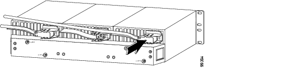
Attaching the Y-Cable
To attach the y-cable to the transponder modules, follow these steps:
Step 1
Step 2
Step 3
Step 4
![]()
![]()
![]()
![]()
![]()
![]()
![]()
![]()
Posted: Mon Dec 6 20:07:35 PST 2004
All contents are Copyright © 1992--2004 Cisco Systems, Inc. All rights reserved.
Important Notices and Privacy Statement.