|
|

Table Of Contents
Protection Schemes and Network Topologies
About Protection Against Fiber and System Failures
Splitter Based Facility Protection
8-Port Multi-Service Muxponders
10-Gbps ITU Tunable and Non tunable Trunk Card
Y-Cable Based Line Card Protection
Client Based Line Card Protection
4-Port 1-Gbps/2-Gbps FC Aggregation Cards
8-Port FC/GE Aggregation Cards
Switch Fabric Based Line Card Protection
Path Switching in Point-to-Point and Ring Topologies
Protection Schemes and Network Topologies
This chapter describes how protection is implemented on the Cisco ONS 15530. It also describes the supported network topologies and how protection works in these topologies. This chapter contains the following major sections:
•
About Protection Against Fiber and System Failures
•
•
•
•
•
About Protection Against Fiber and System Failures
The design of the Cisco ONS 15530 provides the following levels of 1+1 protection:
•
•
•
•
•
Splitter Based Facility Protection
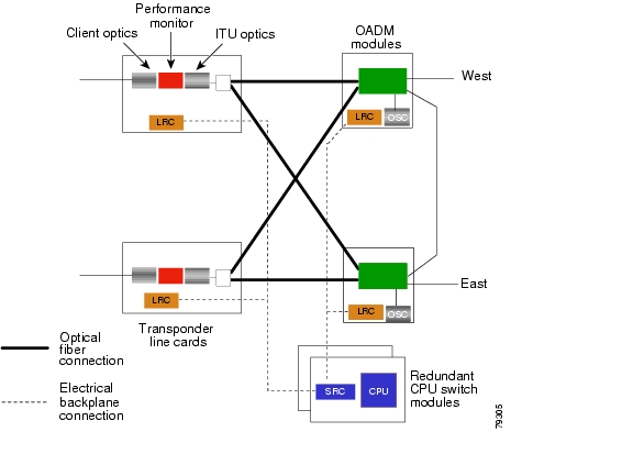
To survive a fiber failure, fiber optic networks are designed with both working and protection fibers. In the event of a fiber cut or other facility failure, working traffic is switched to the protection fiber. The Cisco ONS 15530 supports such facility protection using a splitter scheme (see Figure 2-1) to send the output of the DWDM transmitter on two trunk side interfaces.
Transponder line cards, 8-port multi-service muxponders, 2.5-Gbps ITU trunk cards, 10-Gbps ITU tunable and non tunable trunk cards, and 10-Gbps ITU trunk cards support splitter protection.
Transponder Line Cards
With splitter protection, a passive optical splitter module on the transponder line card duplicates the ITU signal. The front panel of each splitter transponder line card has connectors for two fiber pairs for cabling to the two OADM modules. One fiber pair serves as the active connection, while the other pair serves as the standby. The signal is transmitted on both connections, but in the receive direction, an optical switch selects one signal to be the active one. If a failure is detected on the active receive signal, a switchover to the standby receiver signal occurs under control of the LRC (line card redundancy controller). Assume, for example, that if the active signal in Figure 2-1 is on the east interface, a failure of the signal on that fiber would result in a switchover, and the signal on the west interface would be selected for the receive signal. You can configure preferred working and protection interfaces in the software for the system to use for the active and standby signals, as the signal quality allows.
Figure 2-1 Splitter Protection with Transponder Line Cards
A switchover is triggered in hardware by a loss of light on the receive signal. Switchovers for signal degrade or signal failure are configurable in the software.
Splitter Protection Considerations When Using Transponder Line Cards
The following considerations apply when using splitter protection with transponder line cards:
•
•
•
For rules on how to configure the shelf for splitter protection, see Chapter 6, "Example Shelf Configurations and Topologies." For instructions on configuring the software for splitter protection, refer to the Cisco ONS 15530 Configuration Guide.
8-Port Multi-Service Muxponders
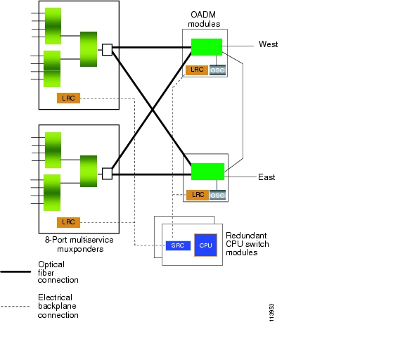
With splitter protection, a passive optical splitter module on the 8-port multi-service muxponder duplicates the ITU signal. The front panel of each splitter 8-port multi-service muxponder has connectors for two fiber pairs for cabling to the two OADM modules. One fiber pair serves as the active connection, while the other pair serves as the standby. The signal is transmitted on both connections, but in the receive direction, an optical switch selects one signal to be the active one. If a failure is detected on the active receive signal, a switchover to the standby receiver signal occurs under control of the LRC (line card redundancy controller). Assume, for example, that if the active signal in Figure 2-1 is on the east interface, a failure of the signal on that fiber would result in a switchover, and the signal on the west interface would be selected for the receive signal. You can configure preferred working and protection interfaces in the software for the system to use for the active and standby signals, as the signal quality allows.
Figure 2-2 Splitter Protection with 8-Port Multi-Service Muxponders
A switchover is triggered in hardware by a loss of light on the receive signal.
Splitter Protection Considerations When Using 8-Port Multi-Service Muxponders
The following considerations apply when using splitter protection with transponder line cards:
•
•
•
For rules on how to configure the shelf for splitter protection, see Chapter 6, "Example Shelf Configurations and Topologies." For instructions on configuring the software for splitter protection, refer to the Cisco ONS 15530 Configuration Guide.
2.5-Gbps ITU Trunk Card
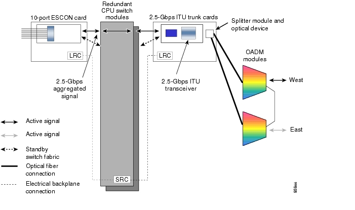
With splitter protection, a passive optical splitter module on the 2.5-Gbps ITU line card duplicates the ITU signal. The front panel of each splitter 2.5-Gbps ITU line card has connectors for two fiber pairs for cabling to the two OADM modules. One fiber pair serves as the active connection, while the other pair serves as the standby. The signal is transmitted on both connections, but in the receive direction, an optical switch selects one signal to be the active one. If a failure is detected on the active receive signal, a switchover to the standby receiver signal occurs under control of the LRC (line card redundancy controller). Assume, for example, that if the active signal in Figure 2-3 is on the east interface, a failure of the signal on that fiber would result in a switchover, and the signal on the west interface would be selected for the receive signal. You can configure preferred working and protection interfaces in the software for the system to use for the active and standby signals, as the signal quality allows.
Figure 2-3 Splitter Protection with 2.5-Gbps ITU Trunk Cards
A switchover is triggered in hardware by a loss of light on the receive signal. Switchovers for signal degrade or signal failure are configurable in the software.
Splitter Protection Considerations When Using 2.5-Gbps ITU Line Cards
The following considerations apply when using splitter protection:
•
•
•
•
For example of how to configure the shelf for splitter protection, see Chapter 6, "Example Shelf Configurations and Topologies." For instructions on configuring the software for splitter protection, refer to the Cisco ONS 15530 Configuration Guide.
10-Gbps ITU Tunable and Non tunable Trunk Card
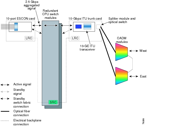
With splitter protection, a passive optical splitter module on the 10-Gbps ITU line card duplicates the ITU signal. The front panel of each splitter 10-Gbps ITU line card has connectors for two fiber pairs for cabling to the two OADM modules. One fiber pair serves as the active connection, while the other pair serves as the standby. The signal is transmitted on both connections, but in the receive direction, an optical switch selects one signal to be the active one. If a failure is detected on the active receive signal, a switchover to the standby receiver signal occurs under control of the LRC (line card redundancy controller). Assume, for example, that if the active signal in Figure 2-4 is on the east interface, a failure of the signal on that fiber would result in a switchover, and the signal on the west interface would be selected for the receive signal. You can configure preferred working and protection interfaces in the software for the system to use for the active and standby signals, as the signal quality allows.
Figure 2-4 Splitter Protection with 10-Gbps ITU Tunable and Non tunable Trunk Cards
A switchover is triggered in hardware by a loss of light on the receive signal. Switchovers for signal degrade or signal failure are configurable in the software.
Splitter Protection Considerations When Using 10-Gbps ITU Line Cards
The following considerations apply when using splitter protection:
•
•
•
•
For example of how to configure the shelf for splitter protection, see Chapter 6, "Example Shelf Configurations and Topologies." For instructions on configuring the software for splitter protection, refer to the Cisco ONS 15530 Configuration Guide.
Y-Cable Based Line Card Protection
The Cisco ONS 15530 supports line card protection for transponder line cards, 4-port 1-Gbps/2-Gbps FC aggregation cards, and 8-port Fibre Channel/Gigabit Ethernet aggregation cards, using a Y-cable scheme. Y-cable protection protects against both facility failures and failure of the line cards. Using an external 2:1 combiner cable (the Y-cable) between the client equipment and the line card interfaces, the client signal is duplicated and sent to two line card interfaces. This arrangement is illustrated in Figure 2-5.
Figure 2-5 Example Y-Cable Protection Scheme Using Transponder Line Cards
In Y-cable protected configurations, one of the line cards functions as the active and the other as the standby. On the active line card, all the lasers and receivers are sending and receiving the client signal. On the standby line card, however, the client side laser is turned off to avoid corrupting the signal transmitted back to the client equipment. The performance monitor on the active line card optically monitors the signal received from the trunk side. If loss of light, signal failure, or signal degrade is detected, and an acceptable standby signal is available, the system switches over to the standby signal. The precise conditions that trigger a switchover based on signal failure or signal degrade are configurable in the alarm threshold software.
Note
Y-Cable Protection Considerations
The following considerations apply when using Y-cable protection:
•
•
•
•
•
•
For rules on how to configure the shelf for Y-cable protection, see "Shelf Configuration Rules." For instructions on configuring the software for y-cable protection, refer to the
Cisco ONS 15530 Configuration Guide.Client Based Line Card Protection
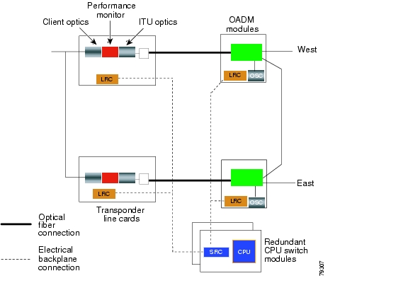
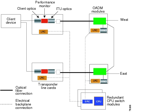
While y-cable protection protects against failures in the transponder line cards and the 8-port Fibre Channel/Gigabit Ethernet aggregation cards or on the fiber, the client still remains vulnerable. For some applications additional protection of the client equipment may be desirable for transponder line card, ESCON aggregation card, and 8-port FC/GE aggregation card applications. The client equipment transmits and receives two separate signals that it monitors. Switchovers are under control of the client rather than the protection mechanisms on the Cisco ONS 15530.
Transponder Line Cards
Figure 2-6 shows the architecture that supports client protection using transponder line cards.
Figure 2-6 Client Based Line Card Protection Scheme for Transponder Line Cards
Considerations for Client Protection with Transponder Line Cards
The following considerations apply when using client protection:
•
•
•
ESCON Aggregation Cards
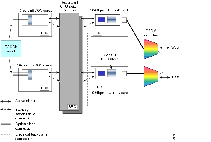
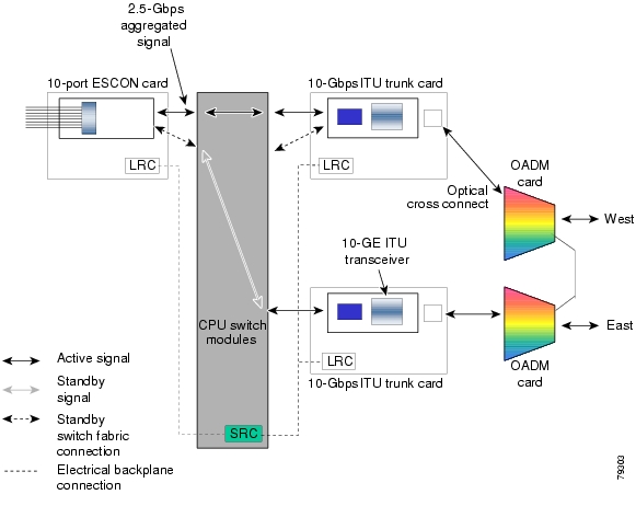
Figure 2-7 shows an example configuration that supports client protection using ESCON aggregation cards and 10-Gbps ITU trunk cards.
Figure 2-7 Client Based Line Card Protection Scheme for ESCON Aggregation Cards and 10-Gbps ITU Trunk Cards
Considerations for Client Protection With 2.5-Gbps ITU Trunk Cards or 10-Gbps ITU Trunk Cards
The following considerations apply when using client protection:
•
•
•
4-Port 1-Gbps/2-Gbps FC Aggregation Cards
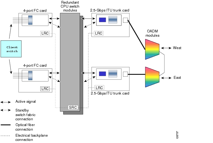
Figure 2-8 shows an example configuration that supports client protection using 4-port 1-Gbps/2-Gbps FC aggregation cards and 2.5-Gbps ITU trunk cards.
Figure 2-8 Client Based Line Card Protection Scheme for 4-Port 1-Gbps/2-Gbps FC Aggregation Cards and 2.5-Gbps ITU Trunk Cards
Considerations for Client Protection With 2.5-Gbps ITU Trunk Cards or 10-Gbps ITU Trunk Cards
The following considerations apply when using client protection:
•
•
•
8-Port FC/GE Aggregation Cards
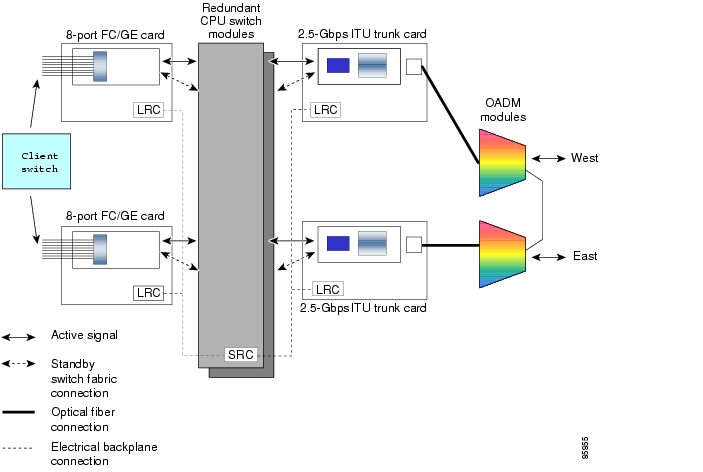
Figure 2-9 shows an example configuration that supports client protection using 8-port Fibre Channel/Gigabit Ethernet aggregation cards and 2.5-Gbps ITU trunk cards.
Figure 2-9 Client Based Line Card Protection Scheme for 8-Port FC/GE Aggregation Cards and 2.5-Gbps ITU Trunk Cards
Considerations for Client Protection With 2.5-Gbps ITU Trunk Cards or 10-Gbps ITU Trunk Cards
The following considerations apply when using client protection:
•
•
•
Switch Fabric Based Line Card Protection
The Cisco ONS 15530 provides facility and trunk or uplink card protection based on the switch fabric connecting one aggregation card to two 2.5-Gbps ITU trunk cards, two 10-Gbps ITU tunable or non tunable trunk cards, or two 10-Gbps uplink cards.
With switch fabric protection, when a signal failure occurs on the trunk fiber or on a trunk card or uplink card, the system switches over to the standby signal. In the case of redundant switch fabrics, a failure in the switch fabric itself causes a switchover to the standby switch fabric. The ESCON aggregation card, 4-port 1-Gbps/2-Gbps FC aggregation card, or 8-port FC/GE aggregation card sends two 2.5-Gbps signals through the active switch fabric to two 2.5-Gbps ITU trunk cards or two 10-Gbps ITU tunable or non tunable trunk cards, one in the east direction and one in the west, or two 10-Gbps uplink cards. The aggregation card only receives the 2.5-Gbps signal from the active switch fabric.
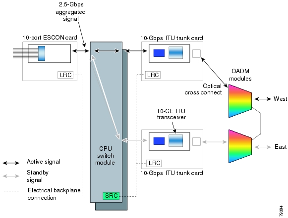
Figure 2-10 shows switch fabric based protection with a single switch fabrics.
Figure 2-10 Switch Fabric Based Protection Example With a Single Switch Fabric
Figure 2-11 shows switch fabric based protection with redundant switch fabrics.
Figure 2-11 Switch Fabric Based Protection Example With Redundant Switch Fabrics
Switch Fabric Based Protection Considerations
The following considerations apply when using switch fabric based protection:
•
•
•
•
•
•
Trunk Fiber Based Protection
The PSM (protection switch module) provides trunk fiber based protection on Cisco ONS 15530 systems configured in point-to-point topologies. This type of protection only provides protection against trunk fiber cuts, not specific channel failure as provided by splitter and line card based schemes. However, this protection scheme allows for much simpler shelf configurations in topologies where per channel protection is not required.
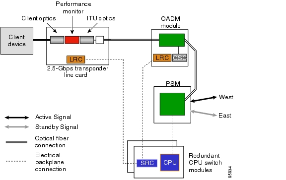
Figure 2-12 shows trunk fiber based protection configured with a transponder line card and an OADM module.
Figure 2-12 Trunk Fiber Based Protection With a Transponder Line Card
Trunk Fiber Based Protection Considerations
The following considerations apply when using trunk fiber based protection:
•
•
•
•
•
•
•
Supported Topologies
The Cisco ONS 15530 can be used in point-to-point and ring topologies. Point-to-point topologies can be either protected and unprotected point-to-point. Ring topologies support add/drop nodes and can be hubbed or meshed. The following sections give a brief overview of these topologies.
Point-to-Point Topologies
In a pure point-to-point topology all channels terminate on the Cisco ONS 15530 nodes at each end of the trunk. Point-to-point topologies have many common applications, including extending the reach of GE or SONET, and can be configured for unprotected or for protected operation.
Unprotected Point-to-Point Topology
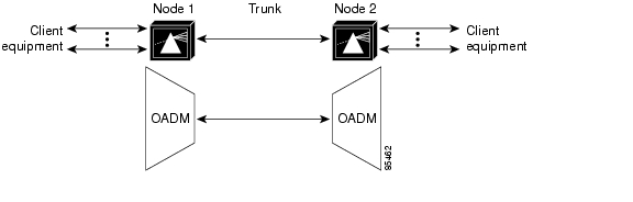
Figure 2-13 shows a point-to-point topology without protection. In this configuration only one optical OADM slot is used in each of the Cisco ONS 15530 nodes. The west or east trunk side interface (OADM module in subslot 0/0 or 0/1) of node 1 connects to the corresponding OADM module on node 2.
Figure 2-13 Unprotected Point-to-Point Topology
For an example configuration of an unprotected point-to-point topology, see Chapter 6, "Example Shelf Configurations and Topologies."
Protected Point-to-Point Topology
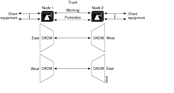
Figure 2-14 shows a protected point-to-point topology configured for splitter or line card per channel protection. In either case, there are two trunk side interfaces, west and east, connected by two fiber pairs.
Figure 2-14 Splitter or Line Card Protected Point-to-Point Topology
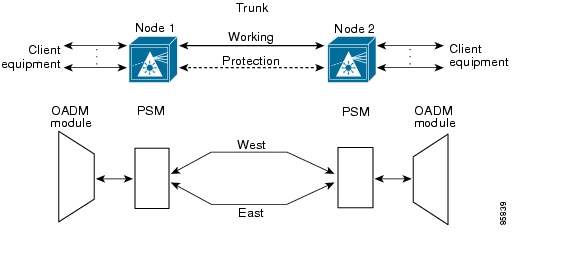
Figure 2-15 shows a protected point-to-point topology configured for trunk fiber protection. There are two trunk side interfaces, west and east, connected by two fiber pairs.
Figure 2-15 Trunk Fiber Protected Point-to-Point Topology
For an example configuration of a protected point-to-point topology, see Chapter 6, "Example Shelf Configurations and Topologies."
Ring Topologies
In a ring topology, client equipment is attached to three or more Cisco ONS 15530 systems, which are interconnected in a closed loop. Channels can be dropped and added at one or more nodes on a ring. Rings have many common applications, including providing extended access to SANs (storage area networks) and upgrading existing SONET rings. In the cases where SONET rings are at capacity, the SONET equipment can be moved off the ring and connected to the Cisco ONS 15530 systems. Then the SONET client signals are multiplexed and transported over the DWDM link, thus increasing the capacity of existing fiber.
Hubbed Ring
A hubbed ring is composed of a hub node and two or more add/drop or satellite nodes. All channels on the ring originate and terminate on the hub node, which is either a Cisco ONS 15540 ESP shelf, a Cisco ONS 15540 ESPx shelf, or Cisco ONS 15530 shelves configured in a multiple shelf node. At add/drop nodes certain channels are terminated (dropped and added back) while the channels that are not being dropped (express channels) are passed through optically, without being electrically regenerated.
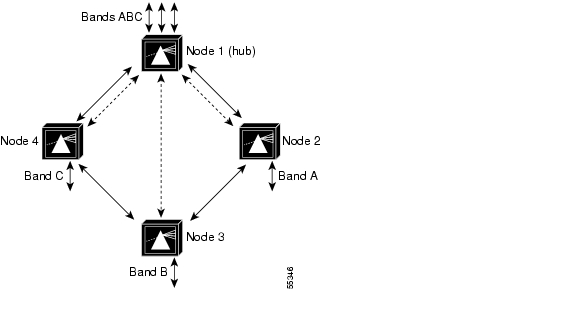
Channels are dropped and added in bands. Figure 2-16 shows a four-node hubbed ring in which bands ABC terminate on node 1. Nodes 1 and 2 communicate using band A, nodes 1 and 3 communicate using band B, and nodes 1 and 4 communicate using band C.
Figure 2-16 Hubbed Ring Topology Example
For example configurations of hubbed ring topologies, see Chapter 6, "Example Shelf Configurations and Topologies."
Meshed Ring
A meshed ring is a physical ring that has the logical characteristics of a mesh. While traffic travels on a physical ring, the logical connections between individual nodes are meshed. An example of this type of configuration, which is sometimes called a logical mesh, is shown in Figure 2-17. Nodes 1 and 2 communicate using band A and nodes 1 and 3 communicate using band B.
Figure 2-17 Meshed Ring Topology Example
For example configurations of meshed ring topologies, see Chapter 6, "Example Shelf Configurations and Topologies."
Path Switching in Point-to-Point and Ring Topologies
The Cisco ONS 15530 supports per-channel unidirectional and bidirectional 1+1 path switching. When a signal is protected and the signal fails, or in some cases degrades, on the active path, the system automatically switches from the active network path to the standby network path.
Signal failures can be total loss of light caused by laser failures, by fiber cuts between the Cisco ONS 15530 and the client equipment, or by other equipment failure. Loss of light failures cause switchovers for both splitter protected and y-cable protected signals. Switchovers based on an alarm threshold can also automatically occur when the signal error rate reaches an unacceptable level.
The Cisco ONS 15530 implements path switching using a SONET-compliant APS channel protocol over the OSC (optical supervisory channel) or the in-band management channel on the protection path.
Note
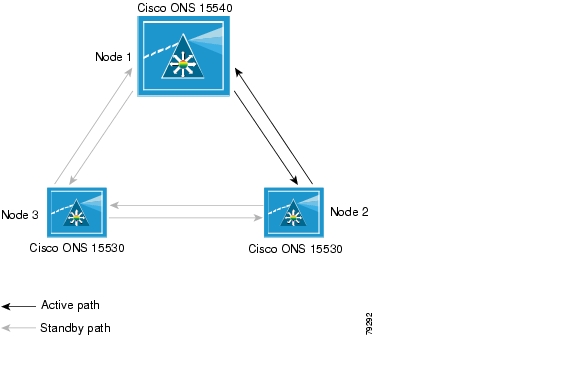
Figure 2-18 shows a protected hubbed ring configuration. The configured working path carries the active signal, and the configured protection path carries the standby signal.
Figure 2-18 Active and Standby Path Configuration Example
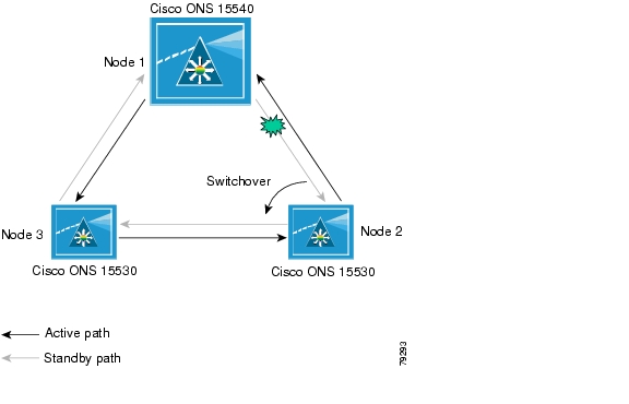
Figure 2-19 shows the behavior of unidirectional path switching when a loss of signal occurs. For the example network, unidirectional path switching operates as follows:
•
•
•
•
Now the nodes are communicating along different paths.
Figure 2-19 Unidirectional Path Switching Example
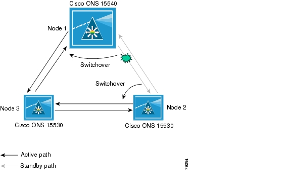
Figure 2-20 shows the behavior of bidirectional path switching when a loss of signal occurs. For the example network, bidirectional path switching operates as follows:
•
•
•
•
•
Both node 1 and node 2 communicate on the same path.
Figure 2-20 Bidirectional Path Switching Overview
![]()
![]()
![]()
![]()
![]()
![]()
![]()
![]()
Posted: Sat Jul 1 01:26:45 PDT 2006
All contents are Copyright © 1992--2006 Cisco Systems, Inc. All rights reserved.
Important Notices and Privacy Statement.