|
|

Table Of Contents
Example Shelf Configurations and Topologies
Splitter Protected Configurations
Line Card Protected Configurations
Switch Fabric Based Line Card Protection Configurations
Trunk Fiber Based Protection Configurations
Multiple Shelf Node Configurations
Meshed Ring Topology Using Multiple Cisco ONS 15530 Shelf Nodes
Cisco ONS 15530 and Cisco ONS 15540 Mixed Topologies
Cisco ONS 15530 and Cisco ONS 15540 Collocated Topologies
Example Shelf Configurations and Topologies
The requirements of a particular topology determine what components must be used and how they are interconnected. This chapter provides examples of shelf configurations and optical power budget calculations specific to each of the main types of protection schemes supported by the Cisco ONS 15530, and examples of supported topologies. This chapter contains the following major sections:
•
Cisco ONS 15530 and Cisco ONS 15540 Mixed Topologies
•
Shelf Configurations
This section describes how to populate a Cisco ONS 15530 shelf for different types of protection configurations.
Unprotected Configurations
This section describes the configuration of the modules and unprotected line cards for unprotected configurations.
Note
Figure 6-1 shows an example of a Cisco ONS 15530 shelf in an unprotected configuration using nonpsplitter transponder line cards.
Figure 6-1 Unprotected Configuration Using Nonsplitter Transponder Line Cards
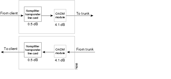
Figure 6-2 shows the optical power budget for an unprotected configuration using nonsplitter transponder line cards.
Figure 6-2 Optical Power Budget for an Unprotected Configuration Using Nonsplitter Transponder Line Cards
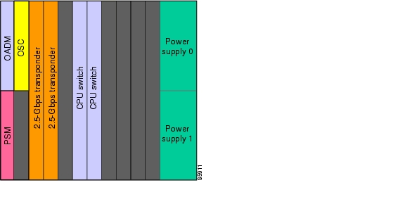
Figure 6-3 shows an example of a Cisco ONS 15530 shelf in an unprotected configuration using ESCON aggregation cards and nonsplitter 2.5-Gbps ITU trunk cards.
Figure 6-3 Unprotected Configuration Using ESCON Aggregation Cards and a 2.5-Gbps ITU Trunk Card
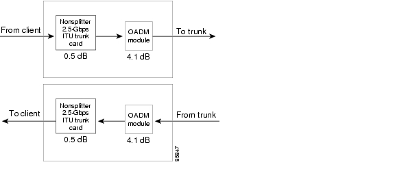
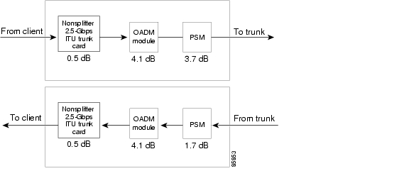
Figure 6-4 shows the optical power budget for an unprotected configuration when using nonsplitter 2.5-Gbps ITU trunk cards.
Figure 6-4 Optical Power Budget for an Unprotected Configuration Using Nonsplitter 2.5-Gbps ITU Trunk Cards
Figure 6-5 shows an example of a Cisco ONS 15530 shelf in an unprotected configuration using 8-port FC/GE aggregation cards and a nonsplitter 10-Gbps ITU trunk card.
Figure 6-5 Unprotected Configuration Using ESCON Aggregation Cards, 8-Port FC/GE Aggregation Card, and 10-Gbps ITU Trunk Cards
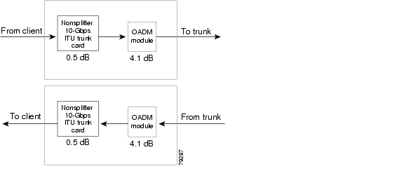
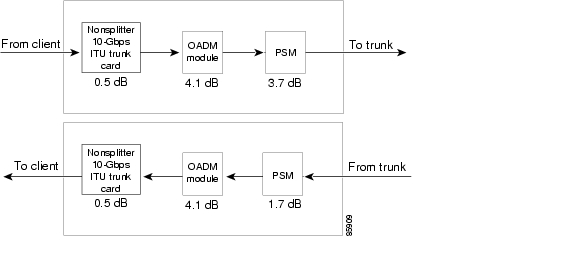
Figure 6-6 shows the optical power budget for an unprotected configuration when using nonsplitter 10-Gbps ITU trunk cards.
Figure 6-6 Optical Power Budget for an Unprotected Configuration Using Nonsplitter 10-Gbps ITU Trunk Cards
Figure 6-7 shows an example of a Cisco ONS 15530 shelf in an unprotected configuration using ESCON aggregation cards and a 10-Gbps uplink card.
Figure 6-7 Unprotected Configuration Using ESCON Aggregation Cards and a 10-Gbps Uplink Card
Figure 6-1 shows an example of a Cisco ONS 15530 shelf in an unprotected configuration using nonpsplitter 8-port multi-service muxponders.
Figure 6-8 Unprotected Configuration Using Nonsplitter 8-Port Multi-Service Muxponders
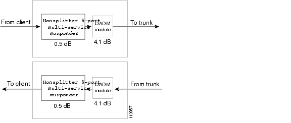
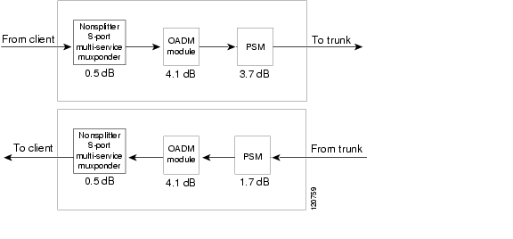
Figure 6-9 shows the optical power budget for an unprotected configuration using nonsplitter 8-port multi-service muxponders.
Figure 6-9 Optical Power Budget for an Unprotected Configuration Using Nonsplitter 8-Port Multi-Service Muxponders
Splitter Protected Configurations
This section describes the configuration of the modules and line cards for splitter protected configurations.
Figure 6-10 shows an example of a Cisco ONS 15530 shelf in a splitter protected configuration using transponder line cards.
Figure 6-10 Splitter Protected Configuration Using Transponder Line Cards
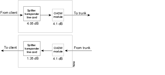
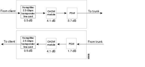
Figure 6-11 shows the optical power budget for a splitter protected configuration.
Figure 6-11 Optical Power Budget for a Splitter Protected Configuration Using Transponder Line Cards
Figure 6-12 shows an example of a Cisco ONS 15530 shelf in a splitter protected configuration using an 8-port FC/GE aggregation cards and 2.5-Gbps ITU trunk cards.
Figure 6-12 Splitter Protected Configuration Using an 8-Port FC/GE Aggregation Card and Splitter 2.5-Gbps ITU Trunk Cards
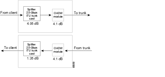
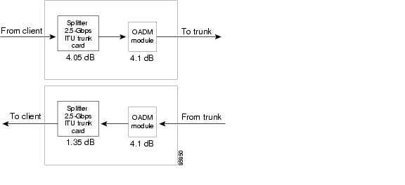
Figure 6-13 shows the optical power budget for a splitter protected configuration.
Figure 6-13 Optical Power Budget for a Splitter Protected Configuration Using Splitter 2.5-Gbps ITU Trunk Cards
Figure 6-14 shows an example of a Cisco ONS 15530 shelf in a splitter protected configuration using ESCON aggregation cards and 10-Gbps ITU trunk cards.
Figure 6-14 Splitter Protected Configuration Using ESCON Aggregation Cards and 10-Gbps ITU Trunk Cards
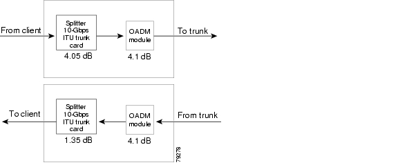
Figure 6-15 shows the optical power budget for a splitter protected configuration.
Figure 6-15 Optical Power Budget for a Splitter Protected Configuration Using 10-Gbps ITU Trunk Cards
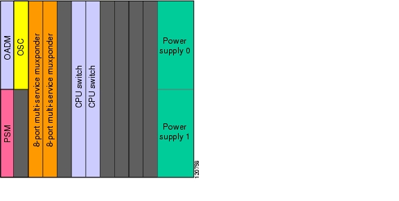
Figure 6-16 shows an example of a Cisco ONS 15530 shelf in a splitter protected configuration using 8-port multi-service muxponders.
Figure 6-16 Splitter Protected Configuration Using 8-Port Multi-Service Muxponders
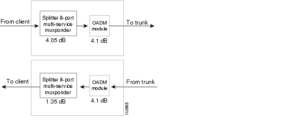
Figure 6-17 shows the optical power budget for a splitter protected configuration using 8-port multi-service muxponders.
Figure 6-17 Optical Power Budget for a Splitter Protected Configuration Using 8-Port Multi-Service Muxponders
Line Card Protected Configurations
This section describes the configuration of the modules and line cards for line card protected configurations.
Figure 6-18 shows an example of a Cisco ONS 15530 shelf in a line card protected configuration using transponder line cards.
Figure 6-18 Line Card Protected Configuration Using Transponder Line Cards
Figure 6-19 shows the optical power budget for a line card protected configuration using nonsplitter transponder line cards.
Figure 6-19 Optical Power Budget for a Line Card Protected Configuration Using Nonsplitter Transponder Line Cards
Figure 6-20 shows an example of a Cisco ONS 15530 shelf in a client based line card protected configuration using ESCON aggregation cards and 2.5-Gbps ITU trunk cards.
Figure 6-20 Client Based Line Card Protected Configuration Using ESCON Aggregation Cards and Nonsplitter 2.5-Gbps ITU Trunk Cards
Figure 6-21 shows the optical power budget for a client based line card protected configuration using nonsplitter 2.5-Gbps ITU trunk cards.
Figure 6-21 Optical Power Budget for a Client Based Line Card Protected Configuration Using Nonsplitter 2.5-Gbps ITU Trunk Cards
Figure 6-22 shows an example of a Cisco ONS 15530 shelf in a client based line card protected configuration using ESCON aggregation cards and 10-Gbps ITU trunk cards.
Figure 6-22 Client Based Line Card Protected Configuration Using ESCON Aggregation Cards and 10-Gbps ITU Trunk Cards
Figure 6-23 shows the optical power budget for a client based line card protected configuration using nonsplitter 10-Gbps ITU trunk cards.
Figure 6-23 Optical Power Budget for a Client Based Line Card Protected Configuration Using Nonsplitter 10-Gbps ITU Trunk Cards
Figure 6-24 shows an example of a Cisco ONS 15530 shelf in a client based line card protected configuration using ESCON aggregation cards and 10-Gbps uplink cards.
Figure 6-24 Client Based Line Card Protected Configuration Using ESCON Aggregation Cards and 10-Gbps Uplink Cards
Figure 6-25 shows an example of a Cisco ONS 15530 shelf in a line card protected configuration using nonsplitter 8-port multi-service muxponders.
Figure 6-25 Line Card Protected Configuration Using Nonsplitter 8-Port Multi-Service Muxponders
Figure 6-26 shows the optical power budget for a line card protected configuration using nonsplitter 8-port multi-service muxponders.
Figure 6-26 Optical Power Budget for a Line Card Protected Configuration Using Nonsplitter 8-Port Multi-Service Muxponders
Switch Fabric Based Line Card Protection Configurations
This section describes the configuration of line cards for switch fabric protected configurations.
Figure 6-27 shows an example of a Cisco ONS 15530 shelf in a switch fabric protected configuration with an ESCON aggregation card and two 2.5-Gbps ITU trunk cards.
Figure 6-27 Switch Fabric Protected Configuration Using Nonsplitter 2.5-Gbps ITU Trunk Cards
Figure 6-28 shows the optical power budget for a switch fabric based line card protected configuration.
Figure 6-28 Optical Power Budget for Switch Fabric Protected Configurations Using Nonsplitter 2.5-Gbps ITU Trunk Cards
Figure 6-29 shows an example of a Cisco ONS 15530 shelf in a switch fabric protected configuration with an ESCON aggregation card and two 10-Gbps ITU trunk cards.
Figure 6-29 Switch Fabric Protected Configuration Using Nonsplitter 10-Gbps ITU Trunk Cards
Figure 6-30 shows the optical power budget for a switch fabric based line card protected configuration.
Figure 6-30 Optical Power Budget for Switch Fabric Protected Configurations Using Nonsplitter 10-Gbps ITU Trunk Cards
Figure 6-31 shows an example of a Cisco ONS 15530 shelf in a switch fabric based line card protected configuration with an ESCON aggregation card and two 10-Gbps uplink cards.
Figure 6-31 Switch Fabric Based Protected Configuration Using 10-Gbps Uplink Cards
Trunk Fiber Based Protection Configurations
This section describes the configuration of line cards for trunk fiber protected configurations.
Figure 6-32 shows an example of a Cisco ONS 15530 shelf in a trunk fiber protected configuration with transponder line cards.
Figure 6-32 Trunk Fiber Protected Configuration Using Nonsplitter Transponder Line Cards
Figure 6-33 shows the optical power budget for a trunk fiber protected configuration with nonsplitter transponder line cards.
Figure 6-33 Optical Power Budget for Trunk Fiber Protected Configurations Using Nonsplitter Transponder Line Cards
Figure 6-34 shows an example of a Cisco ONS 15530 shelf in a trunk fiber protected configuration with 8-port multi-service muxponders.
Figure 6-34 Trunk Fiber Protected Configuration Using Nonsplitter 8-Port Multi-Service Muxponders
Figure 6-35 shows the optical power budget for a trunk fiber protected configuration with nonsplitter 8-port multi-service muxponders.
Figure 6-35 Optical Power Budget for Trunk Fiber Protected Configurations Using Nonsplitter 8-Port Multi-Service Muxponders
Figure 6-36 shows an example of a Cisco ONS 15530 shelf in a trunk fiber protected configuration with an ESCON aggregation card and two nonsplitter 2.5-Gbps ITU trunk cards.
Figure 6-36 Trunk Fiber Protected Configuration Using a Nonsplitter 2.5-Gbps ITU Trunk Card
Figure 6-37 shows the optical power budget for a trunk fiber protected configuration.
Figure 6-37 Optical Power Budget for Trunk Fiber Protected Configurations Using Nonsplitter 2.5-Gbps ITU Trunk Cards
Figure 6-38 shows an example of a Cisco ONS 15530 shelf in a trunk fiber protected configuration with an ESCON aggregation card and two 10-Gbps ITU trunk cards.
Figure 6-38 Trunk Fiber Protected Configuration Using Nonsplitter a 10-Gbps ITU Trunk Card
Figure 6-39 shows the optical power budget for a trunk fiber protected configuration.
Figure 6-39 Optical Power Budget for Trunk Fiber Protected Configurations Using Nonsplitter 10-Gbps ITU Trunk Cards
Note
Multiple Shelf Node Configurations
This section describes multiple shelf nodes consisting of only Cisco ONS 15530 shelves and multiple shelf nodes consisting of Cisco ONS 15530, Cisco ONS 15540 ESP, and Cisco ONS 15540 ESPx shelves.
ITU Linked Configuration
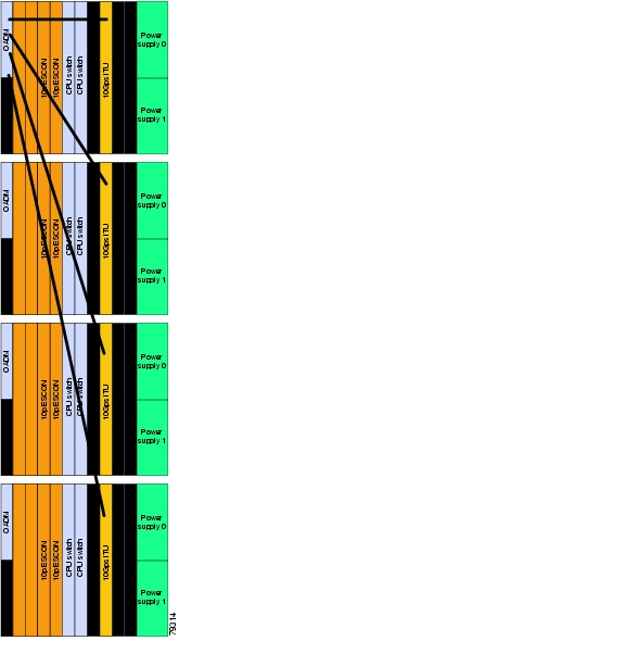
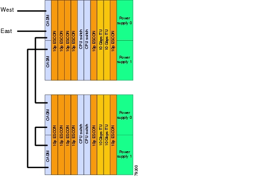
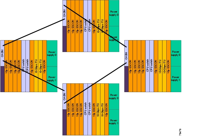
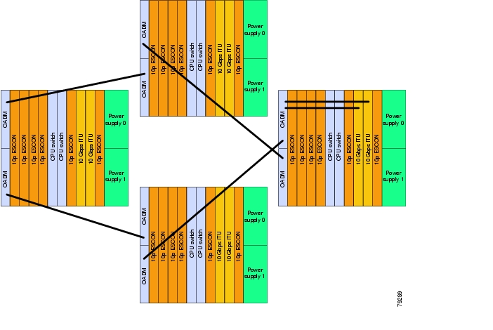
Figure 6-40 shows a multiple shelf node with three Cisco ONS 15530 shelves linked to the OADM modules on a fourth Cisco ONS 15530 shelf.
Figure 6-40 Cisco ONS 15530 Multiple Shelf Node with ITU Uplinking
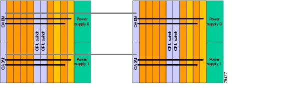
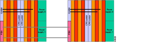
DWDM Linked Configuration
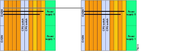
Figure 6-41 shows an example of DWDM linking with two Cisco ONS 15530 shelves linked together via the OADM modules to form a single logical node.
Figure 6-41 DWDM Linking With Two Cisco ONS 15530 Shelves
10-GE Client Signal Uplink Configuration
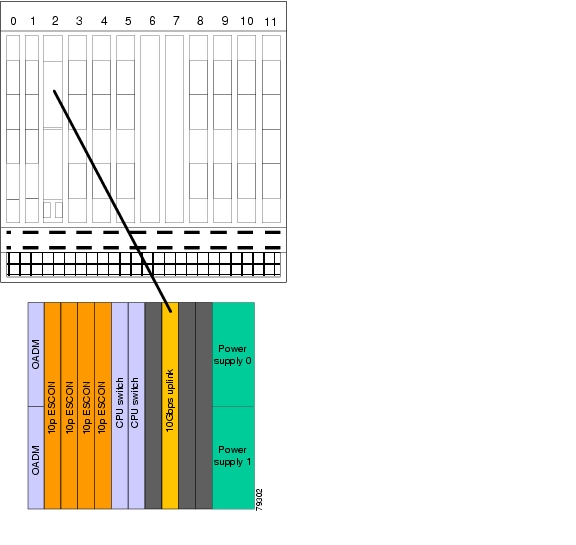
Figure 6-42 shows an example of an unprotected 10-GE client signal linking a Cisco ONS 15530 shelf and a Cisco ONS 15540 ESPx or Cisco ONS 15540 ESP shelf.
Figure 6-42 Unprotected 10-GE Client Signal Linking
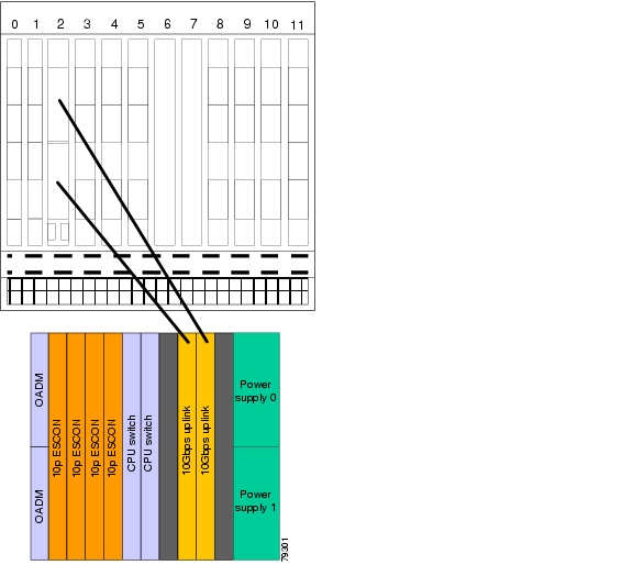
Figure 6-43 shows an example of protected 10-GE client signal linking between a Cisco ONS 15530 shelf and a Cisco ONS 15540 ESPx or Cisco ONS 15540 ESP shelf.
Figure 6-43 Protected 10-GE Client Signal Linking
Cisco ONS 15530 Topologies
The section describes network topologies consisting only of Cisco ONS 15530 shelves. The Cisco ONS 15530 can be configured in the following types of topologies:
•
•
•
Point-to-Point Topologies
The Cisco ONS 15530 supports point-to-point topologies, with or without signal protection. A single shelf supports up to four protected channels and up to eight unprotected channels. To supports more channels, multiple shelf nodes can be used.
Use following criteria to determine the equipment needed for a point-to-point topology:
•
•
•
Unprotected Point-to-Point Topology
Figure 6-44 shows an example of an unprotected point-to-point topology between two Cisco ONS 15530 shelves.
Figure 6-44 Unprotected Point-to-Point Topology
Protected Point-to-Point Topology
Figure 6-45 shows an example of a splitter protected point-to-point topology between two Cisco ONS 15530 shelves.
Figure 6-45 Protected Point-to-Point Topology
Figure 6-46 shows an example of a trunk fiber protected point-to-point topology between two Cisco ONS 15530 shelves.
Figure 6-46 Protected Point-to-Point Topology
Meshed Ring Topologies
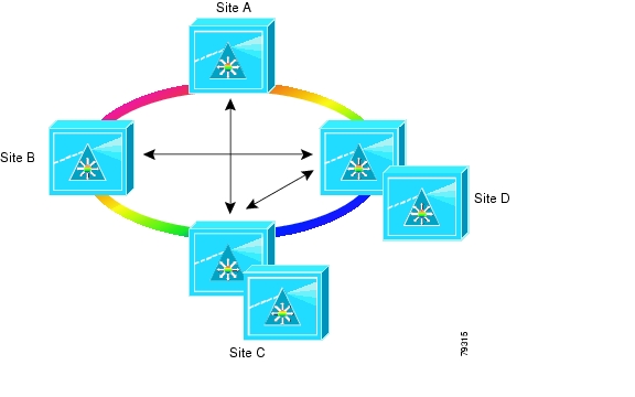
Figure 6-47 shows a logical view of a meshed ring topology consisting of only Cisco ONS 15530 shelves.
Figure 6-47 Meshed Topology
Unprotected Meshed Ring Topology
Figure 6-48 shows an example of an unprotected meshed ring topology consisting of only Cisco ONS 15530 shelves and supporting on four channels.
Figure 6-48 Unprotected Meshed Ring Topology
Protected Meshed Ring Topology
Figure 6-49 shows an example of a protected meshed ring topology consisting of only Cisco ONS 15530 shelves.
Figure 6-49 Protected Meshed Ring Topology
Meshed Ring Topology Using Multiple Cisco ONS 15530 Shelf Nodes
You can configure the Cisco ONS 15530 shelves in a meshed ring topology. The most common application for this configuration is when multiple bands are supported on a node.
Figure 6-50 shows a logical view of a meshed ring topology consisting of Cisco ONS 15530 shelves with multiple shelf nodes.
Figure 6-50 Meshed Ring Topology with Multiple Shelf Nodes
Protected Meshed Ring Topology
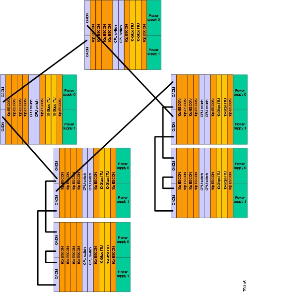
Figure 6-51 shows a protected meshed ring topology consisting of Cisco ONS 15530 shelves with multiple shelf nodes.
Figure 6-51 Protected Meshed Ring Topology with Multiple Shelf Nodes
Cisco ONS 15530 and Cisco ONS 15540 Mixed Topologies
The Cisco ONS 15530, Cisco ONS 15540 ESP, and Cisco ONS 15540 ESPx systems can be used in the same network topology. The most common application is using a Cisco ONS 15540 ESP or Cisco ONS 15540 ESPx as the hub node in a hubbed ring topology.
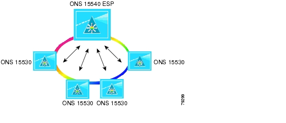
Figure 6-52 shows a logical view of an hubbed ring topology consisting of a Cisco ONS 15540 ESP as the hub node and Cisco ONS 15530 shelves as the spoke nodes. The configuration supports transparent services.
Figure 6-52 Hubbed Ring Topology With a Cisco ONS 15540 ESP Hub
Cisco ONS 15530 and Cisco ONS 15540 Collocated Topologies
The Cisco ONS 15530 can be combine with a Cisco ONS 15540 ESP or Cisco ONS 15540 ESPx system in the same network node. The most common application is using a Cisco ONS 15540 ESP or Cisco ONS 15540 ESPx as the hub node in a hubbed ring topology where aggregated services are required.
Figure 6-53 shows a logical view of an hubbed ring topology consisting of collocated Cisco ONS 15540 ESPx and Cisco ONS 15530 shelves as the hub node and Cisco ONS 15530 shelves as the spoke nodes. This configuration can support transparent and aggregated services.
Figure 6-53 Hubbed Ring Topology With Collocated Cisco ONS 15540 ESP and Cisco ONS 15530 Hub
![]()
![]()
![]()
![]()
![]()
![]()
![]()
![]()
Posted: Sat Jul 1 02:32:57 PDT 2006
All contents are Copyright © 1992--2006 Cisco Systems, Inc. All rights reserved.
Important Notices and Privacy Statement.