|
|

Table Of Contents
4-Port 1-Gbps/2-Gbps FC Aggregation Cards
8-Port FC/GE Aggregation Cards
8-Port Multi-Service Muxponders
10-Gbps ITU Tunable Trunk Cards
Comparison of In-Band Message Channel, SONET, and OSC
System Overview
The Cisco ONS 15530 is an optical transport platform that employs DWDM (dense wavelength division multiplexing) technology. With the Cisco ONS 15530, users can take advantage of the availability of dark fiber to build a common infrastructure that supports data networking and storage networking.
This chapter contains the following major sections:
•
System and Network Management
Chassis Description
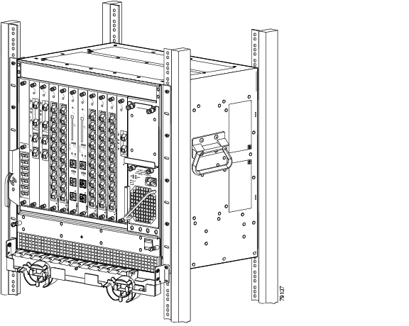
The Cisco ONS 15530 uses an 11-slot modular vertical chassis (see Figure 1-1). As you face the chassis, the leftmost slot (slot 0) holds up to two OADM (optical add/drop multiplexer/demultiplexer) modules. Slots 1 to 4 and 7 to 10 hold the line cards. Slots 5 and 6 hold the CPU switch modules. Air inlet, fan tray, and cable management are located beneath the modular slots. The system has an electrical backplane for system control and signal cross connection via the switch fabric.
The system receives power from two +12 volt redundant power supplies. Both 120V AC and -48V DC power supply options are supported.
Figure 1-1 Cisco ONS 15530 Shelf Layout
Chassis Configurations
There are two versions of the Cisco ONS 15530 chassis, each with different air flow and other mechanical design characteristics. The NEBS (Network Equipment Building System) version of the Cisco ONS 15530 chassis is designed for the North American and other markets. The mechanical design characteristics include the following:
•
•
The other chassis is designed for ETSI (European Telecommunications Standards Institute), a standards organization for the European Union. The mechanical design characteristics include the following:
•
•
For detailed specifications information on the Cisco ONS 15530 chassis, refer to the
Cisco ONS 15530 Hardware Installation Guide.System Functional Overview
The Cisco ONS 15530 connects to client equipment, to the DWDM trunk (transport network), to other Cisco ONS 15530 shelves, and to other DWDM equipment, such as the Cisco ONS 15540 ESP and Cisco ONS 15540 ESPx. Simply described, the Cisco ONS 15530 takes a client signal and converts it to an ITU-T G.692 compliant wavelength, then either optically multiplexes it with the other client signals for transmission over an optical fiber link or sends it through an uplink connection to a Cisco ONS 15540 ESP or Cisco ONS 15540 ESPx.
The Cisco ONS 15530 supports 1+1 path protection using both hardware mechanisms and software based on the APS (Automatic Protection Switching) standard. In a single shelf configuration, a Cisco ONS 15530 node can support up to four channels with facility (fiber) protection or with line card protection, or eight unprotected channels. In a multiple shelf configuration, a node can support up to 32 channels. The Cisco ONS 15530 can be deployed in point-to-point, hubbed ring, and mesh topologies.
The Cisco ONS 15530 is a duplex system with both light emitters and light detectors. For example, the client side interfaces both transmit and receive light. The same is true of the DWDM interface. Also, the OADM modules both multiplex the transmit signal and demultiplex the receive signal.
The Cisco ONS 15530 supports the following two types of transmission modes:
•
•
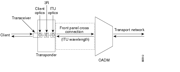
Figure 1-2 illustrates the principal functions involved in transparent transmission of the signal between the client and trunk networks using the transponder line card. Optical cross connections from the front panel of the transponder line card take the signal to the OADM module.
Figure 1-2 Simplified Data Flow Architecture For a Transponder Line Card
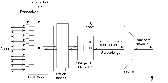
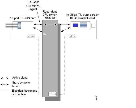
Figure 1-3 illustrates the principal functions involved in transmission of the signal between the client and trunk networks using the ESCON aggregation card and the 10-Gbps ITU trunk card. Electrical cross connections from the backplane side of the ESCON aggregation card take the signal through the switch fabrics on the CPU switch modules to the 10-Gbps ITU trunk card. Optical cross connections from the front panel of the 10-Gbps ITU trunk card take the signal to the OADM module.
Figure 1-3 Simplified Data Flow Architecture For an ESCON Aggregation Card and a 10-Gbps ITU Trunk Card
System Components
The Cisco ONS 15530 has a modular architecture that provides the flexibility to expand the system as the network grows. The Cisco ONS 15530 components are described in the following sections.
Transponder Line Cards
The Cisco ONS 15530 supports two types of transponder line cards: SM (single-mode) and MM (multimode). You can install the transponder line cards in any line card slot in the shelf (slots 1 to 4 and 7 to 10).
In the transponder line card, the client signal is regenerated, retimed, and retransmitted on an ITU-compliant wavelength. The ITU laser on each transponder line card is capable of generating one of two wavelengths on the trunk side. Thus, there are 16 different transponder line cards (for channels 1-2, 3-4,..., 31-32) to support the 32 channels; each module is available in SM and MM versions. The wavelength generated is configurable from the CLI (command-line interface).
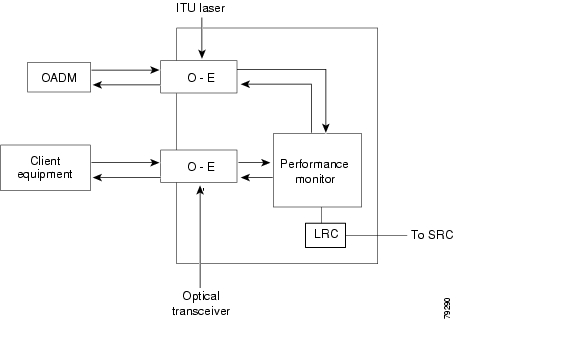
Figure 1-4 shows the architecture of the transponder line card.
Figure 1-4 Transponder Line Card Architecture
A safety protocol, LSC (laser safety control), shuts the transmit laser down on the trunk side when a fiber break or removed connector is detected. The transponder line cards are hot pluggable, permitting in-service upgrades and replacement.
Client Side Interfaces
The client interfaces on the SM transponder line cards and MM transponder line cards are protocol transparent and bit-rate transparent, and accept either single-mode or multimode client signals on the 1310-nm wavelength through SC connectors. The multimode transponder supports 62.5 Βm MM, 50 Βm MM, and 9 or 10 Βm SM fiber; the single-mode transponder supports 50 Βm MM fiber and 9 or 10 Βm SM fiber.
The transponder interfaces support encapsulation of client signals in either 3R (reshape, retime, retransmit) enhanced mode, which allows some client protocol monitoring (such as code violations and data errors) or regular 3R mode, where the transponder is transparent to the client data stream. In either case, the content of the client data stream remains unmodified. Configurable failure and degrade thresholds for monitored protocols are also supported.
Table 1-1 shows the common client signal protocol encapsulations supported on the SM transponder line cards and MM transponders modules.
Table 1-2 shows the IBM storage protocols on the SM transponder line cards and MM transponders modules.
Table 1-2 IBM Storage Protocols Supported on Single-Mode and Multimode Transponders
Encapsulation
MonitoringESCON (200 Mbps)
SM 9 or 10/125 Βm
Yes
No
Yes
Yes
Yes
MM 50/125 Βm
Yes
No
No
Yes
Yes
MM 62.5/125 Βm
Yes
No
No
Yes
Yes
FICON (1062 Mbps)
SM 9 or 10/125 Βm
Yes
No
Yes
No
Yes
MM 50/125 Βm
Yes
No
Yes1
No
Yes
MM 62.5/125 Βm
Yes
No
Yes 1
No
Yes
FICON (2125 Mbps)
SM 9 or 10/125 Βm
Yes
No
Yes
No
Yes
MM 50/125 Βm
Yes
No
Yes2
No
Yes
MM 62.5/125 Βm
Yes
No
Yes 1
No
Yes
Coupling Facility,
ISC-3 compatibility mode (1062 Mbps)SM 9 or 10/125 Βm
Yes
No
Yes
No
Yes
MM 50/125 Βm
Yes
No
Yes 1
No
Yes
MM 62.5/125 Βm
No
No
—
—
—
Coupling Facility,
ISC-3 peer mode (2125 Mbps)SM 9 or 10/125 Βm
Yes
No
Yes
No
Yes
MM 50/125 Βm
No
No
—
—
—
MM 62.5/125 Βm
No
No
—
—
—
Coupling Facility,
ISC-3 peer mode (1062 Mbps)SM 9 or 10/125 Βm
Yes
No
Yes
No
Yes
MM 50/125 Βm
No
No
—
—
—
MM 62.5/125 Βm
No
No
—
—
—
Sysplex Timer (ETR and CLO) (8 Mbps3 )
SM 9 or 10/125 Βm
No
No
—
—
—
MM 50/125 Βm
Yes
No
No
Yes
No
MM 62.5/125 Βm
Yes
No
No
Yes
No
1 These protocols require the use of a special mode-conditioning patch cable (available from IBM) at each end of the connection.
2 These protocols require the use of a special mode-conditioning patch cable (available from IBM) at each end of the connection.
3 Sysplex Timer is the only protocol supported at a clock rate less than 16 Mbps.
Table 1-3 shows some other common protocols that are supported on the SM transponder line cards and MM transponders modules without protocol monitoring.
Additional discrete rates are also supported in regular 3R mode. For SM transponder line cards, these rates fall between 16 Mbps and 2.5 Gbps; for MM transponder line cards, the rates are between 16 Mbps and 622 Mbps.
The system supports OFC (open fiber control) for Fibre Channel and ISC encapsulations. Alternatively, FLC (forward laser control) can be enabled to shut down the laser on the client or trunk side if a Loss of Light is detected on the other side.
The transponder line cards support autonegotiation for Gigabit Ethernet traffic.
Note
For detailed information about client interface configuration, refer to the
Cisco ONS 15530 Configuration Guide.Protocol Monitoring
The transponder line cards can monitor protocol and signal performance. When monitoring is enabled, the system maintains statistics that are used to determine the quality of the signal.
The following protocols can be monitored:
•
•
•
•
•
•
•
•
For GE, FC, and FICON traffic, the Cisco ONS 15530 monitors the following conditions:
•
•
•
•
For SONET errors, the Cisco ONS 15530 monitors the SONET section overhead only, not the SONET line overhead. Specifically, the system monitors the B1 byte and the framing bytes. The system detects the following defect conditions:
•
•
•
•
For SONET performance, the system monitors the B1 byte, which is used to compute the four SONET section layer performance monitor parameters:
•
•
•
•
For ISC-3 traffic, the system monitors the following conditions:
•
•
•
ESCON Aggregation Cards
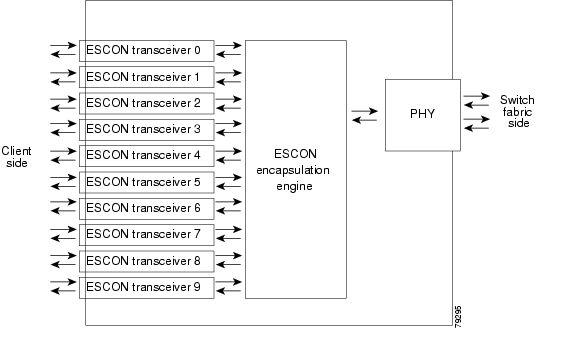
The Cisco ONS 15530 supports a line card specifically for ESCON traffic. The ESCON aggregation card accepts up to 10 SFP (small form-factor pluggable) optics for client traffic. The ESCON aggregation card converts the client signals from optical form to electrical and then aggregates them into a single signal. This aggregated signal passes through the backplane and the switch fabric on the active CPU switch module to a 2.5-Gbps ITU trunk card, 10-Gbps ITU tunable or non tunable trunk card, or a 10-Gbps uplink card (see Figure 1-3). The cross connection between the two cards through the backplane and switch fabrics is configured using the CLI. The ESCON aggregation card has redundant connections over the backplane to the switch fabrics on the active and standby CPU switch modules.
Figure 1-5 shows the architecture of the ESCON aggregation card.
Figure 1-5 ESCON Aggregation Card Architecture
The ESCON aggregation card uses pluggable transceivers with MT-RJ connectors for the client signals. The Cisco ONS 15530 supports up to six ESCON aggregation cards for a total of 60 ESCON signals.
Table 1-4 lists features for the SFP optics supported by the ESCON aggregation cards.
Note
4-Port 1-Gbps/2-Gbps FC Aggregation Cards
The Cisco ONS 15530 supports a line card specifically for 1-Gbps and 2-Gbps FC (Fibre Channel), FICON (Fibre Connection), and ISC (InterSystem Channel) links traffic. The 4-port 1-Gbps/2-Gbps FC aggregation card has the following features:
•
•
•
•
•
•
•
Note
•
Figure 1-6 shows the architecture of the 4-port 1-Gbps/2-Gbps FC aggregation card.
Figure 1-6 4-Port 1-Gbps/2-Gbps FC Aggregation Card Architecture
Table 1-5 lists features for the SFP optics supported by the 4-port 1-Gbps/2-Gbps FC aggregation cards.
Table 1-5 4-Port 1-Gbps/2-Gbps FC Aggregation Card SFP Optics Features
15500-XVRA-02C1
Fibre Channel (1 Gbps)1 , FICON (1 Gbps)
MM 50/125 Βm
MM 62.5/125 Βm850 nm
LC
15500-SFP-GEFC-SX
Fibre Channel (1 Gbps and 2 Gbps)2 , Gigabit Ethernet
MM 50/125 Βm
MM 62.5/125 Βm850 nm
LC
15500-XVRA-03B1
Fibre Channel (1 Gbps)3 , FICON (1 Gbps), ISC links compatibility mode (1 Gbps)
SM 9/125 Βm
1310 nm
LC
15500-XVRA-03B2
SM 9/125 Βm
1310 nm
LC
15500-XVRA-11B1
Mid-band variable rate 200 Mbps to 1.25 Gbps
SM 9/125 Βm
1310 nm
LC
15500-XVRA-12B1
High-band variable rate 1.062 Gbps to 2.488 Gbps
SM 9/125 Βm
1310 nm
LC
15454E-SFP-GEFC-S
Fibre Channel (1-Gbps and 2-Gbps)
MM 50/125 Βm
MM 62.5/125 Βm850 nm
LC
15454-SFP-GEFC-SX
Fibre Channel (1-Gbps and 2-Gbps)
MM 50/125 Βm
MM 62.5/125 Βm850 nm
LC
1 FC-0-100-M5-SN-S and FC-0-100-M6-SN-S standards
2 FC-0-200-M5-SN-S and FC-0-200-M6-SN-S standards
3 FC-0-100-SM-LC-S standard
4 FC-0-100-SM-LC-S standard
5 FC-0-200-SM-LC-S standard
Note
The Cisco ONS 15530 supports up to five 4-port 1-Gbps/2-Gbps FC aggregation cards for a total of 20 1-Gbps client signals.
Protocol Monitoring
For FC and FICON traffic, the system monitors the following conditions on the 4-port 1-Gbps/2-Gbps FC aggregation card:
•
•
•
•
•
•
•
•
•
•
For ISC traffic, the system monitors the following conditions on the 4-port 1-Gbps/2-Gbps FC aggregation card:
•
•
Support for FC Port Types
The 4-port 1-Gbps/2-Gbps FC aggregation card supports the following FC port types, with or without the buffer credit distance extension feature enabled:
•
•
•
•
•
Note
Examples of valid topologies where you can place a Cisco ONS 15530 shelf, which has an 4-port 1-Gbps/2-Gbps FC aggregation card, in the middle to extend distance include the following:
•
•
•
•
•
The arbitrated loop topology is not supported by the 4-port 1-Gbps/2-Gbps FC aggregation card. The arbitrated loop port types not supported include:
•
•
•
Note
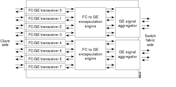
8-Port FC/GE Aggregation Cards
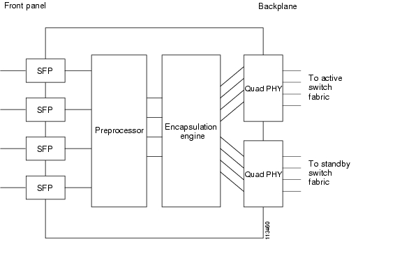
The Cisco ONS 15530 supports a line card specifically for FC (Fibre Channel), FICON (Fibre Connection), GE (Gigabit Ethernet), ISC-1 (InterSystem Channel) links compatibility mode, and 1-Gbps ISC-3 peer mode traffic. The 8-port Fibre Channel/Gigabit Ethernet aggregation card accepts up to eight SFP (small form-factor pluggable) optics for client traffic. Each SFP optic supports FC, FICON, GE, or ISC, depending on how the interface is configured in the CLI.
The 8-port FC/GE aggregation card converts client signals from two adjacent port pairs (0-1, 2-3, 4-5, or 6-7) from optical form to electrical and then aggregates them into four 2.5-Gbps signals. These aggregated signals pass through the backplane and the switch fabric on the active CPU switch module to a 2.5-Gbps ITU trunk card, a 10-Gbps ITU trunk card, or a 10-Gbps uplink card. The cross connections between the two cards through the backplane and switch fabrics is configured using the CLI. The 8-port FC/GE aggregation card has redundant connections over the backplane to the switch fabrics on the active and standby CPU switch modules.
The 8-port FC/GE aggregation card provides buffer credit functionality for Fibre Channel traffic and end-to-end autonegotiation for Gigabit Ethernet traffic.
Note
Note
Figure 1-7 shows the architecture of the 8-port FC/GE aggregation card.
Figure 1-7 8-port FC/GE Aggregation Card Architecture
The 8-port FC/GE aggregation card uses single-mode and multimode SFP optics for the client signals. There are no restrictions on populating the line card with SFPs. For example, you can mix a single-mode SFP optic with a multimode SFP optic in the same port pair. Table 1-6 lists features for the SFP optics supported by the 8-port FC/GE aggregation cards.
Table 1-6 8-Port FC/GE Aggregation Card SFP Optics Features
15500-XVRA-02C1
Gigabit Ethernet1 , Fibre Channel (1 Gbps)2 , FICON (1 Gbps), ISC-3 links compatibility and peer mode (1 Gbps)
MM 50/125 Βm
MM 62.5/125 Βm850 nm
LC
15500-XVRA-03B1
Gigabit Ethernet3 , Fibre Channel (1 Gbps)4 , FICON (1 Gbps), ISC-3 links compatibility and peer mode (1 Gbps)
SM 9/125 Βm
1310 nm
LC
15500-XVRA-11B1
Mid-band variable rate 200 Mbps to 1.25 Gbps
SM 9/125 Βm
1310 nm
LC
15500-XVRA-12B1
High-band variable rate 1.062 Gbps to 2.488 Gbps
SM 9/125 Βm
1310 nm
LC
1 1000BASE-SX
2 FC-0-100-M5-SN-S and FC-0-100-M6-SN-S standards
3 1000BASE-LX
4 FC-0-100-SM-LC-S standard
Note
Note
The Cisco ONS 15530 supports up to four 8-port FC/GE aggregation cards for a total of 32 client signals.
Protocol Monitoring
For GE traffic, the Cisco ONS 15530 monitors the following conditions on the 8-port FC/GE aggregation card:
•
•
•
•
•
•
•
For FC and FICON traffic, the system monitors the following conditions on the 8-port FC/GE aggregation card:
•
•
•
•
•
•
•
•
•
•
For ISC-3 links traffic, the system monitors the following conditions on the 8-port FC/GE aggregation card:
•
•
Support for FC Port Types
The 8-port FC/GE aggregation card supports the following FC port types, with or without the buffer credit distance extension feature enabled:
•
•
•
•
•
Note
Examples of valid topologies where you can place a Cisco ONS 15530 shelf, which has an 8-port FC/GE aggregation card, in the middle to extend distance include the following:
•
•
•
•
•
The arbitrated loop topology is not supported by the 8-port FC/GE aggregation card. The arbitrated loop port types not supported include:
•
•
•
Note
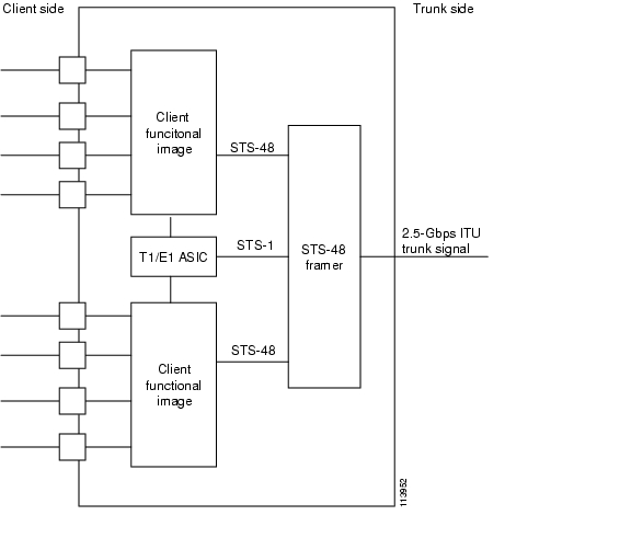
8-Port Multi-Service Muxponders
The 8-port multi-service muxponder accepts up to eight SFPs for client traffic. The eight client signals are mapped into the right size STS-n payloads and multiplexed into a 2.5-Gbps ITU signal. The ITU signal is then multiplexed onto the trunk by an OADM.
Note
The 8-port multi-service muxponder supports the following protocols:
•
•
•
•
•
•
•
•
•
•
•
•
Other features on the 8-port multi-service muxponder include:
•
•
•
The following features are not supported on the 8-port multi-service muxponder:
•
•
•
•
Note
Figure 1-8 shows the architecture of the 8-port multi-service muxponder.
Figure 1-8 8-Port Multi-Service Muxponder Architecture
The 8-port multi-service muxponder uses optical single-mode, optical multimode, and copper SFPs for the client signals. There are no restrictions on populating the line card with SFPs. For example, you can mix a single-mode SFP, a multimode SFP, and a copper SFP in the same muxponder. Table 1-7 lists features for the SFPs supported by the 8-port multi-service muxponders.
Note
The Cisco ONS 15530 supports up to four 8-port multi-service muxponders for a total of 32 client signals in a protected configuration and up to eight 8-port multi-service muxponders for a total of
64 client signals in an unprotected configuration.Protocol Monitoring
The 8-port multi-service muxponder only monitors 8B/10B CVRD errors for GE (optical only), FC, FICON, ESCON, ITS, and ASI traffic.
2.5-Gbps ITU Trunk Cards
The 2.5-Gbps ITU trunk card sends and receives the ITU grid wavelength signal to and from an OADM module. This card accepts a 2.5-Gbps (3.125-Gbps line rate) electrical signal from an ESCON aggregation card, an 8-port FC/GE aggregation card, or a 4-port FC aggregation card, which is converted to the ITU grid wavelength, or channel. The 2.5-Gbps ITU trunk card has redundant interfaces to the backplane, connecting to the switch fabrics on the active and standby CPU switch modules.You can turn the ITU laser to one of two channel frequencies. There are 16 different 2.5-Gbps ITU trunk cards (for channels 1-2, 3-4,..., 31-32) to support the 32 channels.
Note
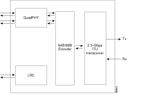
The 2.5-Gbps ITU trunk card has two versions: nonsplitter and splitter. The nonsplitter version has only one pair of optical connectors on the front panel, which connects to either the east or the west OADM module, and can be used for unprotected, line card protected, or switch fabric protected applications (see Figure 1-9).
Figure 1-9 Nonsplitter 2.5-Gbps ITU Trunk Card Architecture
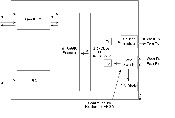
The splitter version of the 2.5-Gbps ITU trunk card has two pairs of optical connectors on the front panel, which connect to the east and west OADM modules, and is designed for splitter protected applications (see Figure 1-10).
Figure 1-10 Splitter 2.5-Gbps ITU Trunk Card Architecture
The Cisco ONS 15530 supports up to four 2.5-Gbps ITU trunk cards for a total of four channels.
10-Gbps ITU Trunk Cards
The 10-Gbps ITU trunk card sends and receives the ITU grid wavelength signal to and from an OADM module. This card accepts up to four 2.5-Gbps (3.125-Gbps line rate) electrical signals from the ESCON aggregation cards, 8-port FC/GE aggregation cards, or a 4-port FC aggregation card, and combines them into one 10-Gbps signal, which is converted to the ITU grid wavelength, or channel. The 10-Gbps ITU trunk card has four separate redundant interfaces to the backplane, each connecting to the switch fabrics on the active and standby CPU switch modules.
Note
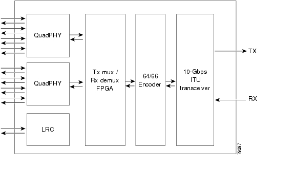
The 10-Gbps ITU trunk card has two version: nonsplitter and splitter. The nonsplitter version has only one pair of optical connectors on the front panel, which connects to either the east or the west OADM module, and can be used for unprotected, line card protected, or switch fabric protected applications (see Figure 1-11).
Figure 1-11 Nonsplitter 10-Gbps ITU Trunk Card Architecture
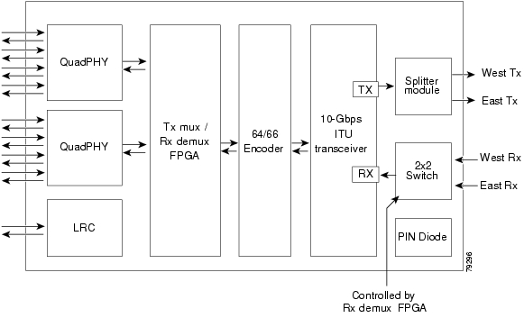
The splitter version of the 10-Gbps ITU trunk card has two pairs of optical connectors on the front panel, which connect to the east and west OADM modules, and is designed for splitter protected applications (see Figure 1-12).
Figure 1-12 Splitter 10-Gbps ITU Trunk Card Architecture
The Cisco ONS 15530 supports up to four 10-Gbps ITU trunk cards for a total of four channels.
10-Gbps ITU Tunable Trunk Cards
The 10-Gbps ITU tunable trunk card sends and receives the ITU grid wavelength signal to and from an OADM module. This card accepts up to four 2.5-Gbps (3.125-Gbps line rate) electrical signals from the ESCON aggregation cards, 8-port FC/GE aggregation cards, or a 4-port FC aggregation card, and combines them into one 10-Gbps signal, which is converted to the ITU grid wavelength, or channel. The 10-Gbps ITU tunable trunk card has four separate redundant interfaces to the backplane, each connecting to the switch fabrics on the active and standby CPU switch modules.
The 10-Gbps tunable trunk card is equipped with tunable lasers, and can be tuned to four different channels belonging to one band. Table 1-8 shows the tunable frequencies and the corresponding wavelengths. You must use the show optical wavelength mapping command to obtain this mapping.
Note
The 10-Gbps ITU tunable trunk card has two version: nonsplitter and splitter. The nonsplitter version has only one pair of optical connectors on the front panel, which connects to either the east or the west OADM module, and can be used for unprotected, line card protected, or switch fabric protected applications (see Figure 1-11).
Figure 1-13 Nonsplitter 10-Gbps ITU Tunable Trunk Card Architecture
The splitter version of the 10-Gbps ITU tunable trunk card has two pairs of optical connectors on the front panel, which connect to the east and west OADM modules and is designed for splitter protected applications (see Figure 1-12).
Figure 1-14 Splitter 10-Gbps ITU Tunable Trunk Card Architecture
The Cisco ONS 15530 supports up to four 10-Gbps ITU tunable trunk cards for a total of 4 channels.
10-Gbps Uplink Cards
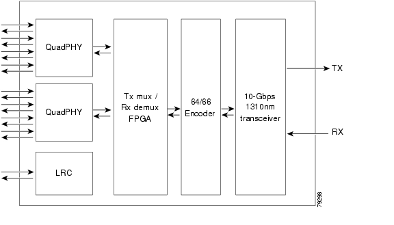
The 10-Gbps uplink card sends and receives a 10-Gbps 1310-nm signal to and from a 10-Gbps uplink card on another Cisco ONS 15530, or to and from a 10-GE transponder module on a Cisco ONS 15540 ESP or Cisco ONS 15540 ESPx. This card accepts up to four (3.125-Gbps line rate) electrical signals from ESCON aggregation cards, 8-port FC/GE aggregation cards, or a 4-port FC aggregation card, and combines them into one 10-Gbps signal (see Figure 1-15).
The 10-Gbps uplink card has four separate redundant interfaces to the backplane. Each interface connects to the switch fabrics on the active and standby CPU switch modules.
Figure 1-15 10-Gbps Uplink Card Architecture
The 10-Gbps uplink card has only one pair of optical connectors on the front panel and can be used for unprotected or line card protected applications. For splitter protected configurations, use the 10-Gbps ITU trunk card.
The Cisco ONS 15530 supports up to four 10-Gbps uplink cards for a total of four channels.
OSC Modules
The Cisco ONS 15530 supports the OSC on a separate module installed in a carrier motherboard. The carrier motherboard accepts up to two OSC modules. Implemented as a 33rd wavelength (channel 0), the OSC is a per-fiber duplex management channel for communicating between Cisco ONS 15530, Cisco ONS 15540 ESP, and Cisco ONS 15540 ESPx systems. The OSC allows control and management traffic to be carried without the necessity of a separate Ethernet connection to each Cisco ONS 15530, Cisco ONS 15540 ESP, and Cisco ONS 15540 ESPx in the network.
The OSC is established over a point-to-point connection and is always terminated on a neighboring node. By contrast, data channels may or may not be terminated on a given node, depending on whether the channels are express (pass-through) or add/drop.
The OSC carries the following types of information:
•
•
•
•
Note
OADM Modules
The OADM (optical add/drop multiplexer/demultiplexer) modules are passive devices that optically multiplex and demultiplex a specific band of 16 ITU wavelengths. The OADM modules supported by the Cisco ONS 15530 each add and drop a band of channels at a node and pass the other bands through. To support the 32-channel spectrum, there are eight different 4-channel OADM modules, each supporting a different band of channels.
In the transmit direction, the OADM modules multiplex signals transmitted by the line cards over optical cross connections and provide the interfaces to connect the multiplexed signal to the DWDM trunk side. In the receive direction, the OADM modules demultiplex the signals from the trunk side before passing them over optical cross connections to the line cards.
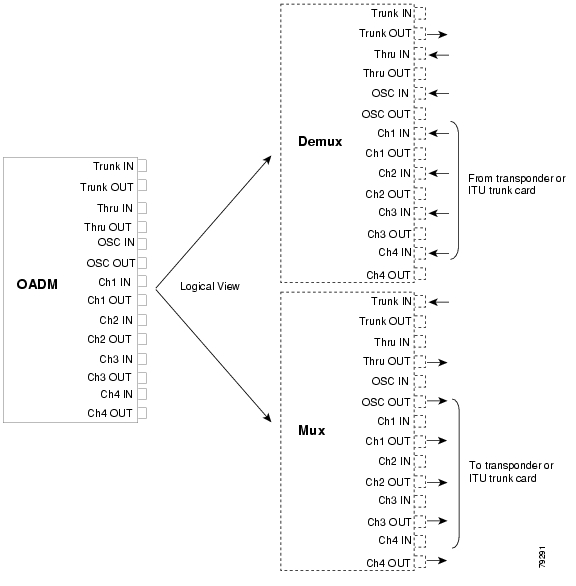
Figure 1-16 shows the physical layout of the OADM module for the channels in band A (1-4) along with a logical view of its multiplexing and demultiplexing functions. Optical signals received from the line card, the Thru IN connector, and the OSC IN connector are multiplexed and sent through the Trunk OUT connector. The optical signal received from the Trunk IN connector is demultiplexed and the OSC signal is sent to the OSC OUT connector; the dropped channels are sent to the line card; and the passed channels are sent to the Thru OUT connector.
Figure 1-16 OADM Module Architecture
OADM Modules and Channel Bands
Each OADM module supports a range of channels called a band. A band contains 4 channels.
Table 1-9 lists the OADM modules that support each channel band. All cards are available with or without OSC support. For correspondence between channel numbers and wavelengths on the ITU grid, refer to the Cisco ONS 15530 Hardware Installation Guide. See Table 1-8 for more information on the tunable frequencies and the corresponding wavelengths.
Table 1-9 OADM Modules and Supported Channel Bands
1-4
Band A
5-8
Band B
9-12
Band C
13-16
Band D
17-20
Band E
21-24
Band F
25-28
Band G
29-32
Band H
OADM Module Configurations
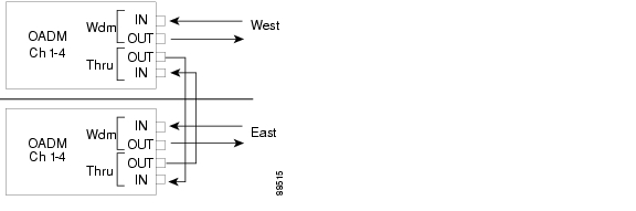
In ring configurations, channels that are not supported by a node are passed through that node and sent out on the ring. Figure 1-17 shows an example of how two OADM modules might be cabled in a protected ring configuration.
Figure 1-17 OADM Modules in a Protected Ring Configuration
PSMs
The PSM (protection switch module) provides trunk fiber protection for Cisco ONS 15530 systems configured in point-to-point topologies. The PSM sends the signal from an OADM module, an ITU trunk card, or a transponder line card to both the west and east directions. It receives both the west and east signals and selects one to send to the OADM module, ITU trunk card, or transponder line card. Both nodes in the network topology must have the same shelf configuration.When a trunk fiber cut occurs on the active path, the PSM switches the received signal to the standby path. Since the PSM occupies one of the OADM subslots in the shelf, it protects a maximum of four channels and the OSC in a single shelf configuration (see Figure 1-18).
The PSM also has a optical monitor port for testing the west and east receive signals. This port samples one percent of the receive signals that can be monitored with an optical power meter.
Figure 1-18 PSM Architecture
CPU Switch Modules
The Cisco ONS 15530 includes two CPU switch modules for redundancy. Each CPU switch module consists of a number of subsystems, including a CPU, a system clock, Ethernet switch for communicating between CPU switch modules and with the LRC (line card redundancy controller) on the OADM modules, line cards, and carrier motherboards, and the SRC (switch redundancy controller). The active CPU switch module controls the node, and all cards in the system make use of the system clock and synchronization signals from the active CPU switch module.
The CPU switch module is equipped with a console port, a Fast Ethernet interface for Telnet access and network management, and an auxiliary port. There is one slot for a compact Flash disk.
On the CPU switch module front panel are LEDs that display the status of critical, major, and minor signals, as well as the status of alarm cutoff and history conditions.
The CPU switch modules run Cisco IOS software and support the following features:
•
•
•
•
•
•
•
•
•
•
•
•
•
Switch Fabric
The Cisco ONS 15530 CPU switch module has a 32-port by 32-port, nonblocking switch fabric, which can carry up to 3.125 Gbps of traffic per port (for data traffic and the remainder for control traffic). The switch fabric connects signals from client side line cards, such as the ESCON aggregation card, to ITU side line cards, such as the 10-Gbps ITU trunk card (see Figure 1-19). When a shelf is configured for CPU switch module redundancy, the redundant switch fabric increases system availability by protecting against switch fabric failures.
Figure 1-19 Redundant Switch Fabrics
Note
CPU Switch Module Redundancy and Online Insertion and Removal
When the Cisco ONS 15530 is powered up, the two CPU switch modules engage in an arbitration process to determine which will be the active and which will be the standby. Previous power state information is stored in the CPU non-volatile random access memory (NVRAM). The CPU that was previously active reassumes the active role. During operation, the two CPU switch modules remain synchronized (application states, running and startup configurations, system images). The operational status of each CPU switch module is monitored by the CPU switch module redundancy controller of the other CPU switch module through the backplane Ethernet. In the event of a failure or removal of an active CPU switch module, the standby CPU switch module immediately takes over and assumes the active role. Once the problem on the faulty card has been resolved, it can be manually restored to the active function.
In addition to providing protection against hardware or software failure, the redundant CPU switch module arrangement also permits installing a new Cisco IOS system image without system downtime. For more information about CPU switch module redundancy operation, as well as other software features, refer to the Cisco ONS 15530 Configuration Guide.
Security Features
The Cisco ONS 15530 supports the following Cisco IOS software security features:
•
•
•
•
•
•
•
For detailed information about the security features supported on the Cisco ONS 15530, refer to the Cisco IOS Security Configuration Guide.
System and Network Management
The Cisco ONS 15530 is fully manageable through any of the following four mechanisms: the in-band message channel, the OSC, SONET SDCC, and a direct Ethernet connection to the NME (network management Ethernet) on the CPU switch module. While all shelves will be equipped with at least one CPU switch module, provisioning the OSC is optional. The in-band message channel is only available on the 2.5-Gbps ITU trunk cards, 10-Gbps ITU tunable and non tunable trunk cards, and 10-Gbps uplink cards. DCC is only available on the 8-port multi-service muxponder.
All four mechanisms can be deployed within a single network. Each mechanism is associated with an interface that can be assigned an IP address. Management information will be routed between these interfaces.
Different levels of availability exist for each of these management mechanisms. High availability for the direct NME connection can be achieved with redundant CPU switch modules. The OSC becomes highly available when it is provisioned on both the working and protection trunk fibers. The availability of a particular in-band message channel or DCC will mirror the availability of the ITU wavelength with which it is associated.
In-Band Message Channel
The in-band message channel establishes a method for providing in-band, per-wavelength OAM&P (operations, administration, management, and provisioning) functions.
The in-band OAM&P messages carry the following types of information:
•
•
•
•
–
–
–
–
•
In-Band Message Channel Consideration
The following considerations apply for the in-band message channel:
•
•
•
DCC
DCC establishes a method for providing in-band, per-wavelength OAM&P (operations, administration, management, and provisioning) functions on the 8-port multi-service muxponder.
The in-band OAM&P messages carry the following types of information:
•
•
DCC Consideration
The following considerations apply for the DCC:
•
•
•
OSC
The OSC is an out-of-band method for providing OAM&P functions on a 33rd wavelength. The OSC supports a message channel that functions like the DCC for management and provisioning. Messages transit the network hop-by-hop, and they can be forwarded or routed according to established routing protocols. The OSC can be used to carry traffic to a network management system, or to carry other internodal management traffic such as link management, fiber failure isolation, performance monitoring, alarms, and APS protocol messages.
OSC Considerations
The following considerations apply for the OSC:
•
•
•
NME
The NME is a 10/100 Ethernet port on the CPU switch module. You can connect this port to a router and configure the interface to route messages using established routing protocols. The NME can be used to carry traffic to a network management system.
Note
NME Considerations
The following considerations apply to the NME:
•
•
Comparison of In-Band Message Channel, SONET, and OSC
Table 1-10 compares the features provided by the in-band message channel, SONET SDCC, and OSC.
Table 1-10 Comparison of the In-Band Message Channel, SONET, and OSC
Management reach
Per fiber section
Per wavelength
Per wavelength
Fault isolation and topology discovery
Hop-by-hop fiber (physical topology)
End-to-end wavelength (logical topology)
End-to-end wavelength (logical topology)
Payload
Separate out-of-band channel
10-GE, Fibre Channel, FICON, GE, ESCON
SONET (OC-n)
Management channel
Per fibre via a 33rd wavelength (channel 0)
Per wavelength via a message byte
Per wavelength via section DCC
Performance monitoring
OSC protocol
8B/10B(GE), 64/66B (10-GE), HEC2 , frame FCS
Section BIP3
1 SONET based management is not supported on the Cisco ONS 15530 and is included for comparison with the in-band message channel only.
2 HEC = Header Error Control
3 BIP = bit interleaved parity
For the most comprehensive set of monitoring and management capabilities, use the in-band message channel, SONET DCC, and OSC on your network. The in-band message channel and SONET DCC provide fault isolation and monitoring at the wavelength level, and OSC provides that functionality for the fiber.
![]()
![]()
![]()
![]()
![]()
![]()
![]()
![]()
Posted: Fri Jun 30 20:49:32 PDT 2006
All contents are Copyright © 1992--2006 Cisco Systems, Inc. All rights reserved.
Important Notices and Privacy Statement.