|
|

Table Of Contents
Cisco ONS 15530 Software Upgrade Guide
Accessing and Displaying File System Devices
Copying the Startup Configuration Files to Flash Memory
Copying Files Between Flash Memory Devices
Viewing the Contents of Flash Memory
Deleting Files from Bootflash Memory
Copying a System Image from a TFTP Server to Flash Memory
Booting from a CompactFlash Card
Accessing System Images on TFTP Servers
Backing Up a System Image to a TFTP Server
Downloading System Images from Cisco.com
Copying System Images to the Cisco ONS 15530
Manually Booting the Cisco ONS 15530
Updating System Images on Redundant Processors
Understanding Functional Images
About Version Diagnostics for ROMMON and Functional Images
Copying Version Diagnostics Data File for ROMMON and Functional Images
Displaying Version Diagnostics for ROMMON and Functional Images
Updating a CPU Switch Module Functional Image Release
Updating Line Card Functional Images
Updating Module Functional Images
Obtaining Technical Assistance
Cisco Technical Support Website
Definitions of Service Request Severity
Obtaining Additional Publications and Information
Cisco ONS 15530 Software Upgrade Guide
This chapter describes how to manage system images, functional images, and configuration files. This chapter includes the following sections:
•
Accessing and Displaying File System Devices
•
•
•
Accessing and Displaying File System Devices
The active processor can read, write, and format files on both the active and standby CPU switch modules. To access devices on the standby CPU switch module from the active CPU switch module, add the prefix "sby-" to the device name.
To display the contents of a file system directory and copy files, use the following commands at the active processor CLI (command-line interface):
dir [fs-name]
Displays the contents of a file system directory.
copy fs-name1[filename1] fs-name2[filename2]
Copies files from one file system to another.
Examples
The following example shows the file system devices accessible from the active CPU switch module:
Switch# dir ?/all List all files/recursive List files recursivelyall-filesystems List files on all filesystemsbootflash: Directory or file namedisk0: Directory or file namenull: Directory or file namenvram: Directory or file namesby-bootflash: Directory or file namesby-disk0: Directory or file namesby-nvram: Directory or file namesystem: Directory or file name<cr>The following example shows how to copy a file from the CompactFlash card on the active CPU switch module to the bootflash: on the active CPU switch module:
Switch# copy disk0:ons15530-i-mz.1 bootflash:ons15530-i-mx.1The following example shows the contents of the standby CPU switch module bootflash directory listed on a terminal accessing the active CPU switch module:
Switch# dir sby-bootflash:Directory of sby-bootflash:/1 -rw- 772 May 29 2001 11:28:51 running-2 -rw- 2452192 May 29 2001 11:27:34 ons15530-i-mz.1Using Flash Memory
This section describes how to use onboard Flash memory, or bootflash memory, and CompactFlash cards to copy system images and make standard configurations. CompactFlash cards use a type of Flash memory that provide expanded file storage for your Cisco ONS 15530. CompactFlash cards, unlike the onboard Flash memory SIMM (bootflash), are not required for the operation of the system.
CompactFlash cards store a copy of the system image. The following sections describe how to format, delete, configure, and copy files between the onboard Flash memory SIMM (Single In-Line Memory Module), network servers, and CompactFlash cards.
Formatting CompactFlash Cards
A newly purchased CompactFlash card is blank and must be formatted before use.
Caution
After inserting the CompactFlash card, format it using the following privileged EXEC command:
Example
The following example shows how to format a CompactFlash card:
Switch# format disk0:Format operation may take a while. Continue? [confirm] yFormat operation will destroy all data in `disk0:'. Continue? [confirm] yFormat:Drive communication & 1st Sector Write OK...Writing Monlibsectors............................................................................................Monlib write completeFormat:All system sectors written. OK...Format:Total sectors in formatted partition:81760Format:Total bytes in formatted partition:49861120Format:Operation completed successfully.Format of disk0:complete
Note
Cisco ONS 15530 Hardware Installation Guide.Copying the Startup Configuration Files to Flash Memory
To copy the startup configuration file from NVRAM to bootflash memory or to a CompactFlash card, once the CompactFlash card is formatted and ready to use, use the following privileged EXEC command:
copy nvram:startup-config {bootflash: | disk0: | sby-disk0:}
Copies the startup-config file from NVRAM to Flash memory.
Example
The following example shows how to copy the startup configuration file to the CompactFlash card; the default filename is used:
Switch#copy nvram:startup-config disk0:Destination filename [startup-config]?y386 bytes copied in 0.268 secsSwitch#Copying Files Between Flash Memory Devices
On platforms with multiple Flash memory file systems, you can copy files from one Flash memory file system, such as internal Flash memory or a CompactFlash card, to another Flash memory file system. Copying files to different Flash memory file systems lets you create backup copies of working configurations, duplicate configurations for other devices, and make copies of system images.
The following example describes how to copy a new system image from Flash memory on the active CPU switch module to a Flash memory on the standby CPU switch module that contains an old system image. If you are copying to a CompactFlash card, first insert the CompactFlash card in the target CPU switch module.
Tips
To copy the new system image file from the CompactFlash card on the active CPU switch module to the CompactFlash card on the standby CPU switch module that contains the old system image file, enter this command from privileged EXEC mode:
Switch#copy disk0:image.new sby-disk0:image.newViewing the Contents of Flash Memory
This section describes commands you can use with the onboard Flash memory SIMM (bootflash) and CompactFlash cards.
Determining the Current File System Device
To determine which file system device you are accessing, use the pwd (print working directory) command, as shown in the following example:
Switch# pwddisk0:/Moving Between Flash Memory Devices
To move between Flash memory devices, use the cd command, as shown in the following example:
Switch# cd bootflash:Switch# pwdbootflash:/Listing the Flash Memory Directory Contents
To list the directory contents of any Flash memory media, use the dir command, as shown in the following example:
Switch# dir disk0:Directory of disk0:/1 -rw- 2438216 May 21 2001 11:44:35 ons15530-i-mz.12 -rw- 2426828 May 23 2001 16:02:49 ons15530-i-mz.2Deleting Files from Bootflash Memory
When you delete a file from bootflash memory, the system marks the file as deleted, allowing you to later recover a deleted file using the undelete command. Erased files cannot be recovered. To permanently erase the configuration file, use the squeeze command.
The squeeze command permanently removes files marked for deletion, and pushes all the other undeleted files together to eliminate spaces between them. To prevent data loss due to sudden power loss, the "squeezed" data is temporarily saved to another location in bootflash memory. The squeeze command keeps a log of the functions performed so that if a power failure occurs, the system continues the process when the power resumes.
Caution
For an example of using the delete and squeeze commands, see the "Updating with Hot-Standby Compatible System Images" section.
Copying a System Image from a TFTP Server to Flash Memory
You can copy system image files from a TFTP server to Flash memory for use in booting the Cisco ONS 15530 or for backup purposes. If the system image on internal Flash memory becomes corrupted, you can replace the system software by copying the backup system image from the CompactFlash card to the onboard Flash memory.
To create a backup of the system software on a TFTP server, perform the following steps:
Step 1
Switch# show {bootflash: | disk0: | sby-disk0:}
Displays the contents of the specified Flash memory device, including the amount of free space that is available.
If enough free space is available, skip to Step 4
Step 2
Switch# delete {bootflash: | disk0: | sby-disk0:} filename
Deletes an old file to make room for the new file.
Step 3
Switch# squeeze bootflash:
Recovers the space used by the files marked as deleted on onboard Flash memory. This command is not necessary for CompactFlash cards.
Step 4
Switch# copy tftp: {bootflash: | disk0: | sby-disk0:}
Copies a file from a TFTP server to a Flash memory device.
Example
The following example shows how to copy a system image file from the default TFTP server to the CompactFlash card:
Switch#copy tftp: disk0:Address or name of remote host []?172.68.16.129Source filename []? ons15530-i-mzDestination filename [ons15530-i-mz]?yBooting from a CompactFlash Card
The Cisco ONS 15530 can be booted, automatically or manually, from a variety of sources, including a network server or Flash memory device. This section describes how to configure the Cisco ONS 15530 to boot automatically from an system image on a CompactFlash card. For an example of configuring the system to boot manually from a CompactFlash card, see the "Updating System Images" section.
To enable booting from a CompactFlash card, perform the following steps:
Step 1
Switch# configure terminal
Switch(config)#
Enters global configuration mode.
Step 2
Switch(config)# no boot system
Disables booting from bootflash.
Step 3
Switch(config)# boot system flash [bootflash: | disk0:][partition-number:][filename]
Enables booting from the specified system image on the specified Flash file system.
Step 4
Switch(config)# config-register 0x2102
Sets the configuration register for automatic booting.1
Step 5
Switch(config)# end
Switch#
Exits global configuration mode.
Step 6
Switch# copy system:running-config nvram:startup-config
Saves the configuration to NVRAM.
Step 7
Switch# reload
Reboots the system.
1 This is the default configuration register setting. For details on using the configuration register to set boot parameters, refer to the Cisco ONS 15530 Configuration Guide.
When you enter boot system commands, be careful not to insert extra spaces because they influence the way the system interprets the command. Notice the difference in the following examples:
Examples
The following command correctly instructs the system to boot the image1 file in onboard Flash memory.
Switch(config)#boot system flash bootflash:image1The following command incorrectly contains a space between "disk0:" and "image2." The system finds the filename field blank and so boots the first file on the CompactFlash card.
Switch(config)#boot system flash disk0: image2Accessing System Images on TFTP Servers
For ease of management, the Cisco ONS 15530 can access TFTP servers for booting and archiving purposes. This sections describes how to access system images on a TFTP server.
Booting from a TFTP Server
This section describes how to configure the Cisco ONS 15530 to boot a system image located on a TFTP server. To boot the standby CPU switch module with an image located on a TFTP server, you must configure the fastethernet-sby 0 interface with a unique IP address on a subnet separate from the subnet used by the fastethernet 0 interface. This configuration prevents conflicts with the fastethernet 0 interface on the active CPU switch module.
Note
To configure booting of a system image located on a TFTP server, perform the following steps:
Step 1
Switch# configure terminal
Switch(config)#
Enters global configuration mode.
Step 2
Switch(config)# config-register 0x2102
or
Switch(config)# config-register 0x0
Sets the configuration register for automatic booting.1
Sets the configuration register for manual booting.
Step 3
Switch(config)# boot system tftp:filename [ip-address]
Enables booting a system image located on a TFTP server for automatic booting.
Step 4
Switch(config)#
interface fastethernet 0Switch(config-if)#
Enters interface configuration mode for interface fastethernet 0, the NME interface on the active CPU switch module.
Step 5
Switch(config-if)#
ip address ip-address subnet-maskSpecifies the IP address and IP subnet mask for the active NME interface.
Step 6
Switch(config-if)#
speed {10 | 100 | auto}Specifies the transmission speed. The default is auto (autonegotiation).
Step 7
Switch(config-if)#
duplex {auto | full | half}Specifies the duplex mode. The default is auto (autonegotiation).
Step 8
Switch(config-if)#
exitSwitch(config)#
Exits interface configuration mode and returns to global configuration mode.
Step 9
Switch(config)#
interface fastethernet-sby 0Switch(config-if)#
Enters interface configuration mode for interface fastethernet-sby 0, the NME interface on the standby CPU switch module.
Step 10
Switch(config-if)#
ip address ip-address subnet-maskSpecifies the IP address and IP subnet mask for the standby NME interface.
Note
Step 11
Switch(config-if)#
speed {10 | 100 | auto}Specifies the transmission speed. The default is auto (autonegotiation).
Note
Step 12
Switch(config-if)#
duplex {auto | full | half}Specifies the duplex mode. The default is auto (autonegotiation).
Note
Step 13
Switch(config-if)#
endSwitch#
Exits interface configuration mode.
Step 14
Switch# copy system:running-config nvram:startup-config
Saves the configuration to NVRAM.
Step 15
Switch# reload
Reboots the system.
1 This is the default configuration register setting. For details on using the configuration register to set boot parameters, refer to the Cisco ONS 15530 Configuration Guide.
Note
For more information on booting system images, refer to the Cisco IOS Configuration Fundamentals Configuration Guide.
Examples
The following example shows how to configure the Cisco ONS 15530 to automatically boot using a system image located on a TFTP server.
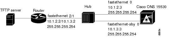
Switch> enableSwitch# configure terminalSwitch(config)# boot system tftp ons15530-i-mz.1 172.20.51.30Switch(config)# config-register 0x2102Switch(config)# interface fastethernet 0Switch(config-if)# ip address 172.20.42.105 255.255.255.254Switch(config-if)# speed 100Switch(config-if)# duplex fullSwitch(config-if)# exitSwitch(config)# interface fastethernet-sby 0Switch(config-if)# ip address 172.20.42.106 255.255.255.254Switch(config-if)# speed 100Switch(config-if)# duplex fullSwitch(config-if)# endSwitch#copy system:running-config nvram:startup-configSwitch#rebootFigure 1 shows a simple network configuration with a TFTP server, a router, a hub, and a Cisco ONS 15530.
Figure 1 Example Network with TFTP Server, Router, Hub, and Cisco ONS 15530
The following example shows how to configure the network example shown in Figure 1.
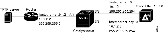
router(config)# interface fastethernet2/1router(config-if)# ip address 10.1.2.2 255.255.255.254router(config-if)# ip address 10.1.3.2 255.255.255.254 secondaryons15530(config)# interface fastethernet 0ons15530(config-if)# ip address 10.1.2.3 255.255.255.254ons15530(config-if)# exitons15530(config)# interface fastethernet-sby 0ons15530(config-if)# ip address 10.1.3.3 255.255.255.254Figure 2 shows a simple network configuration with a TFTP server, a router, a Catalyst 5500, and a Cisco ONS 15530.
Figure 2 Example Network with TFTP Server, Router, Catalyst 5500, Cisco ONS 15530, and VLAN Trunk
The following example shows how to configure the network example shown in Figure 2 with a VLAN trunk.
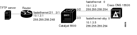
router(config)# interface fastethernet2/1.2router(config-subif)# encapsulation isl 2router(config-subif)# ip address 10.1.2.2 255.255.255.0Cat5500> (enable) set vtp domain CorporateCat5500> (enable) set vtp mode serverCat5500> (enable) set vlan 2Cat5500> (enable) set vlan 2 3/2Cat5500> (enable) set vlan 2 3/3Cat5500> (enable) set trunk 3/1 onons15530(config)# interface fastethernet 0ons15530(config-if)# ip address 10.1.2.4 255.255.255.254ons15530(config-if)# exitons15530(config)# interface fastethernet-sby 0ons15530(config-if)# ip address 10.1.2.6 255.255.255.254Figure 3 shows a simple network configuration with a TFTP server, a router, a Catalyst 5500, and a Cisco ONS 15530.
Figure 3 Example Network with TFTP Server, Router, Catalyst 5500, Cisco ONS 15530, and VLAN
The following example shows how to configure the network example shown in Figure 3 with a VLAN.
router(config)# interface fastethernet2/1router(config-if)# ip address 10.1.3.1 255.255.255.248Cat5500> (enable) set vlan 2Cat5500> (enable) set vlan 2 3/1Cat5500> (enable) set vlan 2 3/2Cat5500> (enable) set vlan 2 3/3ons15530(config)# interface fastethernet 0ons15530(config-if)# ip address 10.1.3.3 255.255.255.254ons15530(config-if)# exitons15530(config)# interface fastethernet-sby 0ons15530(config-if)# ip address 10.1.3.5 255.255.255.254Backing Up a System Image to a TFTP Server
To create a backup copy of your system image, or to verify that the copy in Flash memory is the same as the original file on disk, you can copy system images from Flash memory to a TFTP (Trivial File Transfer Protocol) server.
In some implementations of TFTP, you must create a dummy file on the TFTP server and give it read, write, and execute permissions before copying the file over it. Refer to your TFTP documentation for more information.
Before you copy software between the network server and Flash memory in the router, do the following:
•
•
•
•
To create a backup of the system software on a TFTP server, perform the following steps:
Example
The following example shows how to copy a specified system image file from the current Flash memory device to the default TFTP server:
Switch#copy disk0: tftp:Address or name of remote host []?172.68.16.129Source filename [] ons15530-i-mzDestination filename [ons15530-i-mz]?yUpdating System Images
This section provides minimal instructions for updating system images on your Cisco ONS 15530. The default system configuration causes the system to boot automatically from the system image specified in the BOOT environment variable. This procedure also describes now to update and manually boot the system from a system image on a CompactFlash card. For additional information on booting options and maintaining system images, refer to the Cisco IOS Configuration Fundamentals Configuration Guide.
Downloading System Images from Cisco.com
Cisco IOS system images, along with other software, are available from the Software Center on Cisco.com at http://www.cisco.com. You can download system images from Cisco.com using your browser's FTP capability, using conventional FTP, or using Cisco.com asynchronous dial-up interface.
For instructions on accessing and downloading software from Cisco.com, refer to the document
"Using the Software Center " at the Software Center on Cisco.com.Copying System Images to the Cisco ONS 15530
You can copy the system image to the Cisco ONS 15530 using either TFTP, FTP, or RCP. If the system you used to download the system image from Cisco.com does not function as a TFTP, FTP, or RCP server, you must first copy the file to an intermediate server that provides those services to your system.
Note
Note
To copy the system image from a TFTP server to the Flash memory, initiate a Telnet session or console connection to the system and perform the following steps in privileged EXEC mode:
Step 1
Switch# dir {bootflash: | disk0: | sby-disk0: | sby-bootflash:}
Displays the contents and available space on the Flash memory device. If there is not enough free space to copy the new system image, perform Step 2 and Step 4. Otherwise, proceed to Step 5.
Step 2
Switch# delete {bootflash: | disk0: | sby-disk0: | sby-bootflash:}filename
Marks a file as deleted. If you have older system images stored on the file system, we recommend that you delete the oldest one and leave a newer one in case you need to revert.
Step 3
Switch# squeeze {bootflash: | sby-bootflash:}
Recovers the space used by the files marked as deleted on onboard Flash memory. This command is not necessary for CompactFlash cards.
Step 4
Switch# copy tftp: {bootflash: | disk0: | sby-disk0: | sby-bootflash:}
Initiates a TFTP session to copy the system image from the TFTP server. The system prompts you for a TFTP server name and filename.
Step 5
Switch# dir {bootflash: | disk0: | sby-disk0: | sby-bootflash:}
Displays the contents of the file system. This step confirms that the file was copied as expected.
Example
The following example shows how to delete a file from the CompactFlash card and copy a new system image to it using TFTP:
Switch# dir disk0:Directory of disk0:/1 -rw- 2538248 Dec 05 2001 01:42:30 ons15530-i-mz.121-7a.EY2.bin20578304 bytes total (18040056 bytes free)Switch# delete disk0:ons15530-i-mz.121-7a.EY2.binDelete filename [ons15530-i-mz.121-7a.EY2.bin]? yDelete disk0:ons15530-i-mz.121-7a.EY2 [confirm] ySwitch# copy tftp: disk0:Address or name of remote host [] mochaSource filename [] joe/ons15530-i-mzDestination filename [ons15530-i-mz]Switch# dir disk0:Directory of disk0:/20530200 bytes total (20530200 bytes free)
Note
Manually Booting the Cisco ONS 15530
When the configuration register is set for manual booting, issuing the reload command causes the system to enter ROM monitor mode, where you enter the boot command and the name of the system image to use. To perform this procedure, you must be connected to the console port, which provides access to a system in ROM monitor mode. For automatic booting you can issue the reload command from an Ethernet connection to the processor.
Note
To reload the Cisco ONS 15530 with the new system image on the CompactFlash card, perform the following steps, beginning in global configuration mode:
Step 1
Switch(config)# config-register 0x0
Sets the configuration register for manual booting from ROM monitor mode.1
Step 2
Switch(config)# end
Switch#
Returns to privileged EXEC mode.
Step 3
Switch#
copy system:running-config nvram:startup-configSaves your configuration changes to NVRAM.
Step 4
Switch# reload
Initiates a reload of the system software. The system prompts you to save the modified configuration before you can proceed. You then enter ROM monitor mode.
Step 5
rommon 1> dir filesystem:
Displays the contents of the file system. Perform this optional step to display and copy the name of the system image to the clipboard for use in the next step.
Step 6
rommon 2> boot filesystem:filename
Reboots the system with the new system image. You can paste the filename from the clipboard if you copied it in the previous step.
Step 7
Switch> show version
Displays the system software version information. Use this step to confirm that the system is loaded with the expected software version.
1 For details on using the configuration register to set boot parameters, refer to the
Cisco IOS Configuration Fundamentals Configuration Guide.
Example
The following example shows how to set the configuration register, save the configuration, and reload the Cisco ONS 15530 with the new system image on the CompactFlash card:
Switch(config)# config-register 0x0Switch(config)# endSwitch#copy system:running-config nvram:startup-configDestination filename [startup-config]?Building configuration...[OK]Switch# reloadSystem configuration has been modified. Save? [yes/no]: yWarning: Attempting to overwrite an NVRAM configuration previously writtenby a different version of the system image.Overwrite the previous NVRAM configuration?[confirm] yBuilding configuration...[OK]Proceed with reload? [confirm]rommon 1> dir disk0:Directory of disk0:/1 -rw- 2506076 Jan 01 2000 00:59:36 ons15530-i-mz.121-99.UBLDIT1882 -rw- 2519840 Jan 01 2000 00:02:01 ons15530-i-mz.121-99.UBLDT02010120530200 bytes total (6270284 bytes free)rommon 2> boot disk0:ons15530-i-mz.121-99.UBLDIT188<The system boots.>Switch# show versionCisco Internetwork Operating System SoftwareIOS (tm) ONS-15530 Software (ONS15530-I-M)Copyright (c) 1986-2001 by cisco Systems, Inc.Compiled Wed 15-Aug-01 13:32 by jkoImage text-base: 0x60010950, data-base: 0x60630000ROM: System Bootstrap, Version 12.1(20010726:234219) [ffrazer-lh4 102], DEVELOPMENT SOFTWAREman1 uptime is 14 hours, 59 minutesSystem returned to ROM by reloadSystem image file is "disk0:ons15530-i-mz"cisco ONS15530 (QUEENS-CPU) processor with 98304K/32768K bytes of memory.R7000 CPU at 234Mhz, Implementation 39, Rev 2.1, 256KB L2, 2048KB L3 CacheLast reset from power-on2 FastEthernet/IEEE 802.3 interface(s)509K bytes of non-volatile configuration memory.16384K bytes of Flash internal SIMM (Sector size 256K).Configuration register is 0x0Updating System Images on Redundant Processors
The Cisco ONS 15530 supports software upgrades and downgrades with no interruption of data traffic. You can enter all commands from the currently active processor console connection or Telnet session.
The following upgrade procedures allow you to qualify a new image on one CPU switch module while optionally keeping an older trusted image on the redundant peer CPU switch module.
Caution
Updating with Hot-Standby Compatible System Images
The following procedure describes how to copy a new hot-standby compatible system image from the network to the bootflash device.
Step 1
Step 2
Note
Step 3
Note
Step 4
Step 5
Step 6
Note
Step 7
Step 8
To update the system images on redundant processors, perform the following steps, beginning in privileged EXEC mode:
Step 1
Switch> enable
Enters privileged EXEC mode on the active CPU switch module NME interface.
Step 2
Switch# show version
Displays the configuration register contents. The default autoconfiguration value is 0x2102.
Step 3
Switch# show bootvar
Displays the automatic database synchronization configuration.
Step 4
Switch# show redundancy
Displays the hardware and software redundancy states of the CPU switch modules.
Step 5
Switch# dir sby-bootflash:
Displays the contents and available space on the Flash memory device on the standby processor. If there is not enough free space to copy the new system image, perform Step 6 and Step 7. Otherwise, proceed to Step 8.
Step 6
Switch# delete sby-bootflash:filename
Marks a file as deleted on the standby CPU switch module. If you have older system images stored on the file system, we recommend that you delete the oldest one and leave a newer one in case you need to revert.
Step 7
Switch# squeeze sby-bootflash:
Recovers the space used by the files marked as deleted.
Step 8
Switch# copy tftp:new-image-name sby-bootflash:
Initiates a TFTP session to copy the system image from the TFTP server to the Flash memory device on the standby CPU switch module. The system prompts you for a TFTP server name and filename.
Step 9
Switch# dir sby-bootflash:
Displays the contents of the standby CPU switch module file system and confirms that the file was copied as expected.
Step 10
Switch# configure terminal
Enters global configuration mode.
Step 11
Switch(config)# boot system bootflash:new-image-name
Adds the new system image to the system boot list.
Step 12
Switch(config)# no boot system bootflash:old-image-name
Removes the old system image from the top of the system boot list.
Step 13
Switch(config)# boot system bootflash:old-image-name
Adds the old system image to the system boot list after the new system image.
Step 14
Switch(config)# exit
Exits global configuration mode.
Step 15
Switch# show running-config
Shows the current running configuration to verify the order of the boot system commands. The new system image should appear first.
Step 16
Switch# copy system:running-config nvram:startup-config
Saves the configuration to NVRAM.
Step 17
Switch# copy system:running-config tftp:
Saves the configuration to a TFTP server. (Optional)
Step 18
Switch# redundancy reload peer
Initiates a reload of the system image on the standby CPU switch module.
Step 19
Switch# show redundancy
Displays the CPU switch module redundancy status and images Verify that the standby CPU switch module is running the desired new image.
Note
Step 20
Switch# redundancy switch-activity
Switches system control over to the standby CPU switch module by reloading the system image on the active CPU switch module.
Repeat Step 1 through Step 9 and then Step 16 through Step 19 if no problems occur with the new system image on the active CPU switch module.
Updating with Non-Hot-Standby Compatible System Images
System images with widely different version numbers might not allow the standby CPU switch module to reach hot-standby state. A different upgrade procedure is necessary to handle these cases.
Caution
To update between system images that are not hot-standby compatible, perform the following steps on the active CPU switch module:
Step 1
Switch> enable
Switch#
Enters privileged EXEC mode on the active CPU switch module NME interface.
Step 2
Switch# show version
Displays the configuration register contents. The default autoconfiguration value is 0x2102.
Step 3
Switch# show bootvar
Displays the automatic database synchronization configuration.
Step 4
Switch# show redundancy
Displays the hardware and software redundancy states of the CPU switch modules.
Step 5
Switch# dir bootflash:
Displays the contents and available space on the Flash memory device on the active CPU switch module. If there is not enough free space to copy the new system image, perform Step 6 and Step 7. Otherwise, proceed to Step 8.
Step 6
Switch# delete bootflash:filename
Marks a file as deleted on the active CPU switch module. If you have older system images stored on the file system, we recommend that you delete the oldest one and leave a newer one in case you need to revert.
Step 7
Switch# squeeze bootflash:
Recovers the space used by the files marked as deleted.
Step 8
Switch# copy tftp:new-image-name bootflash:
Initiates a TFTP session to copy the system image from the TFTP server to the Flash memory device on the active CPU switch module. The system prompts you for a TFTP server name and filename.
Step 9
Switch# dir bootflash:
Displays the contents of the active CPU switch module file system and confirms that the file was copied as expected.
Step 10
Switch# dir sby-bootflash:
Displays the contents and available space on the Flash memory device on the standby CPU switch module. If there is not enough free space to copy the new system image, perform Step 11 and Step 12. Otherwise, proceed to Step 13.
Step 11
Switch# delete sby-bootflash:filename
Marks a file as deleted on the standby CPU switch module. If you have older system images stored on the file system, we recommend that you delete the oldest one and leave a newer one in case you need to revert.
Step 12
Switch# squeeze sby-bootflash:
Recovers the space used by the files marked as deleted.
Step 13
Switch# copy tftp:new-image-name sby-bootflash:
Initiates a TFTP session to copy the system image from the TFTP server to the Flash memory device on the standby CPU switch module. The system prompts you for a TFTP server name and filename.
Step 14
Switch# dir sby-bootflash:
Displays the contents of the standby CPU switch module file system and confirms that the file was copied as expected.
Step 15
Switch# configure terminal
Switch(config)#
Enters global configuration mode.
Step 16
Switch(config)# boot system bootflash:new-image-name
Adds the new system image to the system boot list.
Step 17
Switch(config)# no boot system bootflash:old-image-name
Removes the old system image from top of the system boot list.
Step 18
Switch(config)# boot system bootflash:old-image-name
Adds the old system image to the system boot list after the new system image.
Step 19
Switch(config)# exit
Switch#
Exits global configuration mode.
Step 20
Switch# show running-config
Shows the current running configuration to verify the order of the boot system commands. The new system image should appear first.
Step 21
Switch# copy system:running-config nvram:startup-config
Saves the configuration to NVRAM.
Step 22
Switch# copy system:running-config tftp:
Saves the configuration to a TFTP server. (Optional)
Step 23
Switch# configure terminal
Switch(config)#
Enters global configuration mode.
Step 24
Switch(config)# redundancy
Switch(config-red)#
Enters redundancy configuration mode.
Step 25
Switch(config-red)# maintenance-mode
Disables database autosynchronization between the CPU switch modules and puts the standby CPU switch module in cold-standby state.
Step 26
Switch(config-red)# end
Switch#
Returns to privileged EXEC mode.
Step 27
Switch# redundancy reload peer
Initiates a reload of the system image on the standby CPU switch module.
Step 28
Switch# show redundancy
Displays the CPU switch module redundancy status and images. Verify that the standby CPU switch module is running the desired new image and is in either the NEGOTIATION state or the STANDBY COLD state.
Step 29
Switch# redundancy switch-activity force
Switches system control over to the standby CPU switch module by reloading the system image on the active CPU switch module.
Updating Functional Images
You can load functional images used by certain hardware controllers in the Cisco ONS 15530. This section describes the function and maintenance of functional image.
Understanding Functional Images
Functional images provide the low-level operating functionality for various hardware controllers. On hardware controllers with insystem programmable devices, such as field programmable gate arrays (FPGAs) and Erasable Programmable Logic Devices (EPLDs), the hardware functional images can be reprogrammed independently of loading the system image and without removing the devices from the controller.
On the Cisco ONS 15530, you can reprogram the functional images on the CPU switch modules, OSC modules, WB-VOA modules, PB-OE module, and line cards.
All new hardware is shipped with functional images preloaded. Loading a different functional image is required only when upgrading or downgrading functional image versions.
About Version Diagnostics for ROMMON and Functional Images
The ROMMON and functional images must be upgraded correctly to ensure proper functioning of the system. To ensure that the correct functional image versions are installed on your system, you can download a data file that you can use to verify your system status.
You can download the version diagnostics data file from Cisco.com from the following URL:
http://www.cisco.com/cgi-bin/tablebuild.pl/ons15530-fpga
Copying Version Diagnostics Data File for ROMMON and Functional Images
You can copy the data file with version diagnostics for the ROMMON and functional images from either a TFTP server or from an FTP server.
Copying a Version Diagnostics Data File from a TFTP Server to Flash Memory
To download a version diagnostics data file from a TFTP server, perform the following steps:
Step 1
Switch# dir {bootflash: | disk0:}
Verifies that space is available in Flash memory on the active CPU switch module. If space is available, continue to Step 3.
Step 2
Switch# delete {bootflash: | disk0:}filename
(Optional) Deletes a file from Flash memory.
Step 3
Switch# squeeze bootflash:
(Optional) Recovers the space in onboard Flash memory.
Step 4
Switch# copy tftp:[[[//location]/directory]/filename] {bootflash: | disk0:}[filename]
Copies the data file from the TFTP server to the Flash memory device.
Reply to any CLI prompts for additional information or confirmation. The prompting depends on how much information you provide in the copy command.
Note
Step 5
Switch# dir {bootflash: | disk0:}
Displays information about the files in Flash memory, including the file sizes. Use the file size information to ensure that the entire file downloaded correctly.
Example
The following example shows how to download an version diagnostics data file from a TFTP server:
Switch# dir bootflash:Directory of bootflash:/1 -rw- 3241396 Mar 06 2000 22:18:02 ons15530-i-mz.v121_12ev2 -rw- 7593 Jul 03 2003 15:59:54 running-config15990784 bytes total (9485748 bytes free)Switch# copy tftp: bootflash:Address or name of remote host? 10.0.0.1Source filename?fi-ons15530-index.006.datDestination filename [fi-ons15530-index.006.dat]?Accessing tftp://10.0.0.1/fi-ons15530-index.006.dat...Loading /tftpboot/fi-ons15530-index.006.dat from 10.0.0.1 (via FastEthernet0): ![OK - 2860 bytes]2860 bytes copied in 0.216 secs (13241 bytes/sec)Switch# dir bootflash:Directory of bootflash:/1 -rw- 3241396 Mar 06 2000 22:18:02 ons15530-i-mz.v121_12ev2 -rw- 7593 Jul 03 2003 15:59:54 running-config3 -rw- 2860 Sep 13 2003 17:00:22 fi-ons15530-index.006.dat15990784 bytes total (9482760 bytes free)Copying a Version Diagnostics Data File from an FTP Server to Flash Memory
To download an version diagnostics data file from an FTP server, perform the following steps
Step 1
Switch# configure terminal
Switch(config)#
(Optional) Enters configuration mode from the terminal. This step is required only if you override the default remote username (see Step 2 and Step 3). Otherwise, continue to Step 5.
Step 2
Switch(config)# ip ftp username username
(Optional) Changes the default remote username.
Step 3
Switch(config)# ip ftp password password
(Optional) Changes the default password.
Step 4
Switch(config)# end
Switch#
(Optional) Exits configuration mode. This step is required only if you override the default remote username (see Step 2 and Step 3).
Step 5
Switch# dir {bootflash: | disk0:}
Verifies that space is available in Flash memory. If space is available, continue to Step 8.
Step 6
Switch# delete {bootflash: | disk0:}filename
(Optional) Deletes a file from Flash memory.
Step 7
Switch# squeeze bootflash:
(Optional) Recovers the space in onboard Flash memory.
Step 8
Switch# copy ftp:[[[//[username[:password]@]location]/
directory]/filename] {bootflash: | disk0:}[filename]Copies the data file from the FTP server to the Flash memory device.
Reply to any CLI prompts for additional information or confirmation. The prompting depends on how much information you provide in the copy command.
Note
Step 9
Switch# dir {bootflash: | disk0:}
Displays information about the files in Flash memory, including the file sizes. Use the file size information to ensure that the entire file downloaded correctly.
:
Example
Switch# dir bootflash:Directory of bootflash:/1 -rw- 3241396 Mar 06 2000 22:18:02 ons15530-i-mz.v121_12ev2 -rw- 7593 Jul 03 2003 15:59:54 running-config15990784 bytes total (9485748 bytes free)Switch# copy ftp://myuser:mypass@theserver/tftpboot/fi-ons15530-index.006.dat disk0:fi-ons15530-index.006.datSwitch# dir bootflash:Directory of bootflash:/1 -rw- 3241396 Mar 06 2000 22:18:02 ons15530-i-mz.v121_12ev2 -rw- 7593 Jul 03 2003 15:59:54 running-config3 -rw- 2860 Sep 13 2003 17:00:22 fi-ons15530-index.006.dat15990784 bytes total (9482760 bytes free)Displaying Version Diagnostics for ROMMON and Functional Images
To display the most recent data file with the ROMMON and functional image version diagnostics, perform the following steps
Switch# show update-info functional-image {all | latest-version [software-compatible]} dat-file device:filename [detail]
Displays the ROMMON and functional image version diagnostics.
:
Example
The following example shows how display the functional image version information for the system:
Switch# show upgrade-info functional-image all dat-file fi-ons15530-index.010.datValidating CRC...100%Generating Functional Image Upgrade Information for the currently running IOSusing DAT file fi-ons15530-index.010.dat, created on Thu Aug 21 00:23:10 PST 2003.Please ensure that you are using the latest DAT file fromCisco Connection Online (CCO) WebpageAbbr: Cur.FV = Functional Image Version of the Card.Lis.FV = List of Func. Image Versions found in the DAT-file for thecorresponding card.(U) = IOS Software upgrade is required, to upgrade tothe recommended functional image version.Slot Product No Cur.FV Lis.FV Listed Functional Image---- ------------------------- ------ ------ -------------------------------1/* 15530-TSP1-2912= 3.12 3.12 No Func. Image Upgrade Required1/0 Unknown 1.A2 1.A2 No Func. Image Upgrade Required2/* 15530-TSP1-3112 3.55 3.55 No Func. Image Upgrade Required2/0 Unknown 1.F2 1.F2 No Func. Image Upgrade Required3/* 15530-TSP1-2911 3.11 3.12 fi-ons15530-tpd.A.3-12.exo3/0 Unknown 1.9F 1.A0 fi-ons15540-tlcmdb.A.1-A0.exo4/* PROTO-HAMPTON-ESCON 2.33 2.36 fi-ons15530-escon.A.2-36.exo5/* PROTO-HAMPTON-CPU 1.43 1.43 No Func. Image Upgrade Required5/0 Active Rommon 1.1 1.1 No Func. Image Upgrade Required6/* PROTO-HAMPTON-CPU 1.43 1.43 No Func. Image Upgrade Required6/0 Standby Rommon 1.1 1.1 No Func. Image Upgrade Required8/* PROTO-HAMPTON-OSCMB 1.37 1.37 No Func. Image Upgrade Required8/0 15530-OSCM 0.58 0.58 No Func. Image Upgrade Required8/1 15530-OSCM 0.58 0.58 No Func. Image Upgrade RequiredUpdating a CPU Switch Module Functional Image Release
The CPU switch modules on the Cisco ONS 15530 have two images, a ROMMON image and a functional image.
To update a CPU switch module functional images for the active and redundant CPU switch modules, follow these steps:
Step 1
Step 2
Step 3
Step 4
Step 5
Note
Cisco IOS Configuration Fundamentals Configuration Guide, Release 12.1.
Caution
Determining the CPU Switch Module Functional Image Release Version
To determine the existing CPU switch module functional image or CPU switch module functional image release version, use the following command in EXEC mode:
show hardware detail linecard slot
Displays the functional image information.
show version
Displays the ROMMON image information.
Example
The following example shows the ROMMON image version information:
Switch# show versionCisco Internetwork Operating System SoftwareIOS (tm) ONS-15530 Software (ONS15530-i-mz), Release Version 12.1(10)EVCopyright (c) 1986-2001 by cisco Systems, Inc.Compiled Fri 23-Mar-02 15:23 byImage text-base:0x60010950, data-base:0x604E8000ROM:System Bootstrap, Version 12.1(12c)E1, RELEASE SOFTWARE
Switch uptime is 30 minutesSystem returned to ROM by power-onSystem image file is "disk0:ONS15530-m0-mz"cisco (QUEENS-CPU) processor with 98304K/32768K bytes of memory.R7000 CPU at 234Mhz, Implementation 39, Rev 2.1, 256KB L2, 2048KB L3 CacheLast reset from power-on2 Ethernet/IEEE 802.3 interface(s)509K bytes of non-volatile configuration memory.20480K bytes of Flash PCMCIA card at slot 0 (Sector size 128K).16384K bytes of Flash internal SIMM (Sector size 64K).Configuration register is 0x102The following example shows the functional image version for the CPU switch module in slot 5:
Switch# show hardware linecard 5---------------------------------------------------------------------Slot Number : 5/*Controller Type : 0x1100On-Board Description : Prote-Hampton_CPUOrderable Product Number: PROTO-HAMPTON-CPUBoard Part Number : 73-6572-04Board Revision : 06Serial Number : CAB0602M9XXManufacturing Date : mm/dd/2001Hardware Version : 4.6RMA Number :RMA Failure Code :Updating a CPU Switch Module Functional Image from a TFTP Server
To download a CPU switch module functional image from a TFTP server and upgrade the functional image on both CPU switch modules, perform the following steps, starting with the active CPU switch module:
Step 1
Switch# show {bootflash: | disk0:}
Verifies that space is available in Flash memory on the active CPU switch module. If space is available, continue to Step 4.
Step 2
Switch# delete {bootflash: | disk0:}filename
(Optional) Deletes a file from Flash memory.
Step 3
Switch# squeeze bootflash:
(Optional) Recovers the space in onboard Flash memory.
Step 4
Switch# copy tftp:[[[//location]/directory]/filename] {bootflash: | disk0:}[filename]
Copies the image from the TFTP server to the Flash memory device.
Reply to any CLI prompts for additional information or confirmation. The prompting depends on how much information you provide in the copy command.
Note
Step 5
Switch# show {sby-bootflash: | sby-disk0:}
Verifies that space is available in Flash memory on the standby CPU switch module. If space is available, continue to Step 8.
Step 6
Switch# delete {sby-bootflash: | sby-disk0:}filename
(Optional) Deletes a file from Flash memory.
Step 7
Switch# squeeze sby-bootflash:
(Optional) Recovers the space in onboard Flash memory.
Step 8
Switch# copy tftp:[[[//location]/directory]/filename] {sby-bootflash: | sby-disk0:}[filename]
Copies the image from the TFTP server to the Flash memory device.
Reply to any CLI prompts for additional information or confirmation. The prompting depends on how much information you provide in the copy command.
Note
Step 9
Switch# reprogram {sby-bootflash: | sby-disk0:}filename {slot | sby-rommon}
Updates the CPU switch module functional image on the CPU switch module and returns the CPU switch module to ROMMON mode.
Step 10
rommon 1 > boot [{bootflash: | disk0:}filename]
(Optional) Boots the IOS system image on the standby CPU switch module if it does not boot automatically.
Step 11
Switch# redundancy switch-activity [force]
Switches over control to the standby CPU switch module.
Repeat Step 9 through Step 10 on the new standby CPU switch module.
Note
Example
The following example shows how to download a ROMMON image from a TFTP server and update the ROMMON image on the active CPU switch module:
Switch#show disk0:-#- ED --type-- --crc--- -seek-- nlen -length- -----date/time------ name1 .. image 1BD2EA73 2A7B24 26 2652836 Feb 11 2002 18:07:41 ons15530-i-mz2 .. config 36DC62E3 2AAC54 14 12461 Feb 11 2002 18:10:34 running-config17912748 bytes available (2665556 bytes used)Switch#copy tftp: disk0:Address or name of remote host []?10.0.0.1Source filename []?ONS15530_RM.srecDestination filename [ONS15530_RM.srec]?yLoading tftpboot/ONS15530_RM.srec from 10.0.0.1 (via Ethernet3/0):!!!!!!!!!!!!!!!!!!!!!!!!!!!!!!!!!!!!!!!!!!!!!!!!!!!!!!!!!!!!!!!!!!!!!!!!!!!!!!!!!!!!!!!!!!!!!!!!!!!!!!!!!!!!!!!!!!!!!!!!!!!!!!!!!!!!!!!!!!!!!!!!!!!!!!!!!!!!!!!!!!!!!!!!!!!!!!!!!!!!!!!!!!!!!!!!!!!!!!!!!!!!!!!!!!!!!!!!!!!!!!!!!!!!!!!!!!!!!!!!!!!!!!!!!!!!!!!!!!!!!!!!!!!!!!!!!!!!!!!!!!!!!!!!!!!!!!!!!!!!!!!!!!!!!!!!![OK -629458/17912748bytes]629458 bytes copiedUpdating a CPU Switch Module Functional Image from an FTP Server
To download a CPU switch module functional image from an FTP server and upgrade the functional image on both CPU switch modules, perform the following steps, starting with the active CPU switch module:
Step 1
Switch# configure terminal
Switch(config)#
(Optional) Enters configuration mode from the terminal. This step is required only if you override the default remote username (see Step 2 and Step 3). Otherwise, continue to Step 9.
Step 2
Switch(config)# ip ftp username username
(Optional) Changes the default remote username.
Step 3
Switch(config)# ip ftp password password
(Optional) Changes the default password.
Step 4
Switch(config)# end
Switch#
(Optional) Exits configuration mode. This step is required only if you override the default remote username (see Step 2 and Step 3).
Step 5
Switch# show {bootflash: | disk0:}
Verifies that space is available in Flash memory on the active CPU switch module. If space is available, continue to Step 8.
Step 6
Switch# delete {bootflash: | disk0:}filename
(Optional) Deletes a file from Flash memory.
Step 7
Switch# squeeze bootflash:
(Optional) Recovers the space in onboard Flash memory.
Step 8
Switch# copy ftp:[[[//[username[:password]@]location]/ directory]/filename] {bootflash: | disk0:}[filename]
Copies the image from the FTP server to the Flash memory device.
Reply to any CLI prompts for additional information or confirmation. The prompting depends on how much information you provide in the copy command.
Note
Step 9
Switch# show {sby-bootflash: | sby-disk0:}
Verifies that space is available in Flash memory on the standby CPU switch module. If space is available, continue to Step 12.
Step 10
Switch# delete {sby-bootflash: | sby-disk0:}filename
(Optional) Deletes a file from Flash memory.
Step 11
Switch# squeeze sby-bootflash:
(Optional) Recovers the space in onboard Flash memory.
Step 12
Switch# copy ftp:[[[//[username[:password]@]location]/ directory]/filename] {sby-bootflash: | sby-disk0:}[filename]
Copies the image from the FTP server to the Flash memory device.
Reply to any CLI prompts for additional information or confirmation. The prompting depends on how much information you provide in the copy command.
Note
Step 13
Switch# reprogram {sby-bootflash: | sby-disk0:}filename {slot | sby-rommon}
Updates the functional image on the standby CPU switch module and returns the standby CPU switch module to ROMMON mode.
Step 14
rommon 1 > boot [{bootflash: | disk0:}filename]
(Optional) Boots the IOS system image on the standby CPU switch module if it does not boot automatically.
Step 15
Switch# redundancy switch-activity [force]
Switches over control to the standby CPU switch module.
Repeat Step 13 through Step 14 on the new standby CPU switch module.
Note
Example
The following example shows how to download a ROMMON image from an FTP server and update the ROMMON image on the active CPU switch module:
Switch#show disk0:-#- ED --type-- --crc--- -seek-- nlen -length- -----date/time------ name1 .. image 1BD2EA73 2A7B24 26 2652836 Feb 11 2002 18:07:41 ons15530-i-mz2 .. config 36DC62E3 2AAC54 14 12461 Feb 11 2002 18:10:34 running-config17912748 bytes available (2665556 bytes used)Switch# copy ftp://myuser:mypass@theserver/tftpboot/ONS15530_RM.srec disk0:ONS15530_RM.srecAccessing ftp://theserver/tftpboot/ONS15530_RM.srec...Translating "theserver"...domainserver (192.168.2.132) [OK]Loading ONS15530_RM.srec from 192.168.2.132 (via Ethernet3/0):!!!!!!!!!!!!!!!!!!!!!!!!!!!!!!!!!!!!!!!!!!!!!!!!!!!!!!!!!!!!!!!!!!!!!!!!!!!!!!!!!!!!!!!!!!!!!!!!!!!!!!!!!!!!!!!!!!!!!!!!!!!!!!!!!!!!!!!!!!!!!!!!!!!!!!!!!!!!!!!!!!!!!!!!!!!!!!!!!!!!!!!!!!!!!!!!!!!!!!!!!!!!!!!!!!!!!!!!!!!!!!!!!!!!!!!!!!!!!!!!!!!!!!!!!!!!!!!!!!!!!!!!!!!!!!!!!!!!!!!!!!!!!!!!!!!!!!!!!!!!!!!!!!!!!!!!!!!!!!!!!!!!!!!!!!!!!!!!!!!!!!!!!!!!!!!!!!!!!!!!!!!!!!!!!!!!!!!!!!!!!!!!!!!!!!!!!!!!!!!!!!!!!!!!!!!!!!!!!!!!!!!!!!!!!!!!!!!!!!!!!!!!!!!!!!!!!!!!!!!!!!!!!!!!!!!!!!!!!!!!!!!!!!!!!!!!![OK - 623492/17912748bytes]623492 bytes copiedUpdating Line Card Functional Images
You update a line card functional image in three steps:
Step 1
Step 2
Step 3
Determining the Line Card Functional Image Version
To determine the functional image version in a line card hardware controller, use the following command in privileged EXEC mode:
The following example shows the functional image information in the controller for the line card in slot 3:
Switch# show hardware linecard 3--------------------------------------------------------------------------------Slot Number : 3/*Controller Type : 0x1101On-Board Description : HAMPTON-ESCONOrderable Product Number: PROTO-HAMPTON-ESCONBoard Part Number : 73-7710-03Board Revision : 01Serial Number : CAB0602M9PVManufacturing Date : 04/08/2002Hardware Version : 3.2RMA Number :RMA Failure Code :Functional Image Version: 2.36 (dec), 2.24 (hex)Copying a Line Card Functional Image from a TFTP Server to Flash Memory
To download a line card functional image from a TFTP server, perform the following steps:
Step 1
Switch# show {bootflash: | disk0:}
Verifies that space is available in Flash memory on the active CPU switch module. If space is available, continue to Step 3.
Step 2
Switch# delete {bootflash: | disk0:}filename
(Optional) Deletes a file from Flash memory.
Step 3
Switch# squeeze bootflash:
(Optional) Recovers the space in onboard Flash memory.
Step 4
Switch# copy tftp:[[[//location]/directory]/filename] {bootflash: | disk0:}[filename]
Copies the image from the TFTP server to the Flash memory device.
Reply to any CLI prompts for additional information or confirmation. The prompting depends on how much information you provide in the copy command.
Note
Example
The following example shows how to download a functional image from a TFTP server and update the functional image on the active CPU switch module:
Switch#show disk0:-#- ED --type-- --crc--- -seek-- nlen -length- -----date/time------ name1 .. image 1BD2EA73 2A7B24 26 2652836 Feb 11 2002 18:07:41 ons15530-i-mz2 .. config 36DC62E3 2AAC54 14 12461 Feb 11 2002 18:10:34 running-config17912748 bytes available (2665556 bytes used)Switch#copy tftp: disk0:Address or name of remote host []?10.0.0.1Source filename []?fi-ons15530-escon.A.2-36.exoDestination filename [fi-ons15530-escon.A.2-36.exo]?yLoading tftpboot/ fi-ons15530-escon.A.2-36.exo from 10.0.0.1 (via Ethernet3/0):!!!!!!!!!!!!!!!!!!!!!!!!!!!!!!!!!!!!!!!!!!!!!!!!!!!!!!!!!!!!!!!!!!!!!!!!!!!!!!!!!!!!!!!!!!!!!!!!!!!!!!!!!!!!!!!!!!!!!!!!!!!!!!!!!!!!!!!!!!!!!!!!!!!!!!!!!!!!!!!!!!!!!!!!!!!!!!!!!!!!!!!!!!!!!!!!!!!!!!!!!!!!!!!!!!!!!!!!!!!!!!!!!!!!!!!!!!!!!!!!!!!!!!!!!!!!!!!!!!!!!!!!!!!!!!!!!!!!!!!!!!!!!!!!!!!!!!!!!!!!!!!!!!!!!!!!![OK -5779602/17912748bytes]5779602 bytes copiedCopying a Line Card Functional Image from an FTP Server to Flash Memory
To download a line card functional image from an FTP server, perform the following steps
Step 1
Switch# configure terminal
Switch(config)#
(Optional) Enters configuration mode from the terminal. This step is required only if you override the default remote username (see Step 2 and Step 3). Otherwise, continue to Step 5.
Step 2
Switch(config)# ip ftp username username
(Optional) Changes the default remote username.
Step 3
Switch(config)# ip ftp password password
(Optional) Changes the default password.
Step 4
Switch(config)# end
Switch#
(Optional) Exits configuration mode. This step is required only if you override the default remote username (see Step 2 and Step 3).
Step 5
Switch# show {bootflash: | disk0:}
Verifies that space is available in Flash memory. If space is available, continue to Step 8.
Step 6
Switch# delete {bootflash: | disk0:}filename
(Optional) Deletes a file from Flash memory.
Step 7
Switch# squeeze bootflash:
(Optional) Recovers the space in onboard Flash memory.
Step 8
Switch# copy ftp:[[[//[username[:password]@]location]/ directory]/filename] {bootflash: | disk0:}[filename]
Copies the image from the FTP server to the Flash memory device.
Reply to any CLI prompts for additional information or confirmation. The prompting depends on how much information you provide in the copy command.
Note
:
Example
The following example shows how to download a functional image from an FTP server:
Switch#show disk0:-#- ED --type-- --crc--- -seek-- nlen -length- -----date/time------ name1 .. image 1BD2EA73 2A7B24 26 2652836 Feb 11 2002 18:07:41 ons15530-i-mz2 .. config 36DC62E3 2AAC54 14 12461 Feb 11 2002 18:10:34 running-config17912748 bytes available (2665556 bytes used)Switch# copy ftp://myuser:mypass@theserver/tftpboot/fi-ons15530-escon.A.2-36.exo disk0:fi-ons15530-escon.A.2-36.exoAccessing ftp://theserver/tftpboot/ONS15530_RM.srec...Translating "theserver"...domainserver (192.168.2.132) [OK]Loading ONS15530_RM.srec from 192.168.2.132 (via Ethernet3/0):!!!!!!!!!!!!!!!!!!!!!!!!!!!!!!!!!!!!!!!!!!!!!!!!!!!!!!!!!!!!!!!!!!!!!!!!!!!!!!!!!!!!!!!!!!!!!!!!!!!!!!!!!!!!!!!!!!!!!!!!!!!!!!!!!!!!!!!!!!!!!!!!!!!!!!!!!!!!!!!!!!!!!!!!!!!!!!!!!!!!!!!!!!!!!!!!!!!!!!!!!!!!!!!!!!!!!!!!!!!!!!!!!!!!!!!!!!!!!!!!!!!!!!!!!!!!!!!!!!!!!!!!!!!!!!!!!!!!!!!!!!!!!!!!!!!!!!!!!!!!!!!!!!!!!!!!!!!!!!!!!!!!!!!!!!!!!!!!!!!!!!!!!!!!!!!!!!!!!!!!!!!!!!!!!!!!!!!!!!!!!!!!!!!!!!!!!!!!!!!!!!!!!!!!!!!!!!!!!!!!!!!!!!!!!!!!!!!!!!!!!!!!!!!!!!!!!!!!!!!!!!!!!!!!!!!!!!!!!!!!!!!!!!!!!!!!![OK - 623492/17912748bytes]623492 bytes copiedUpdating the Line Card Functional Image
To update a line card functional image from a Flash memory device to a hardware controller, use the following command in privileged EXEC mode from a console session:
reprogram device:filename slot
Updates the functional image with the specified filename to a device.
The reprogram command checks the compatibility of the image for the selected card type before downloading the functional image. If you have specified a slot number without a subcard, the functional image is downloaded to the full-width module that occupies that slot.
Caution
Caution
Example
The following example demonstrates loading the functional image fpga_image from the CompactFlash Card to the controller for the processor in slot 8.
Switch# reprogram disk0:fpga_image 8Updating Module Functional Images
You can update the functional image for the OSC modules.
Update a module functional image in three steps:
Step 1
Step 2
Step 3
Determining the Module Functional Image Version
To determine the functional image version in a module hardware controller, use the following command in privileged EXEC mode:
The following example shows the functional image information in the controller for the line card in slot 2:
Switch# show hardware linecard 2--------------------------------------------------------------------------------Slot Number : 2/*Controller Type : 0x1103On-Board Description : Prototype Hampton OscmbOrderable Product Number: PROTO-HAMPTON-OSCMBBoard Part Number : 73-6838-04Board Revision : 01Serial Number : CAB0603MAJ1Manufacturing Date : 01/24/2002Hardware Version : 4.0RMA Number :RMA Failure Code :Functional Image Version: 1.36Function-ID : 0--------------------------------------------------------------------------------Slot Number : 2/0Controller Type : 0x1107On-Board Description : Prototype Hampton OscdcOrderable Product Number: PROTO-HAMPTON-OSCDCBoard Part Number : 73-7238-03Board Revision : 03Serial Number : CAB0602MA36Manufacturing Date : 12/07/2001Hardware Version : 3.1RMA Number :RMA Failure Code :Functional Image Version: 0.52Function-ID : 0Transceiver type : Non-pluggable Transceiver--------------------------------------------------------------------------------Slot Number : 2/1Controller Type : 0x1107On-Board Description : Prototype Hampton OscdcOrderable Product Number: PROTO-HAMPTON-OSCDCBoard Part Number : 73-7238-03Board Revision : 03Serial Number : CAB0602MA3HManufacturing Date : 12/07/2001Hardware Version : 3.1RMA Number :RMA Failure Code :Functional Image Version: 0.52Function-ID : 0Transceiver type : Non-pluggable TransceiverCopying a Module Functional Image from a TFTP Server to Flash Memory
To download a module functional image from a TFTP server, perform the following steps:
Step 1
Switch# show {bootflash: | disk0:}
Verifies that space is available in Flash memory on the active CPU switch module. If space is available, continue to Step 3.
Step 2
Switch# delete {bootflash: | disk0:}filename
(Optional) Deletes a file from Flash memory.
Step 3
Switch# squeeze bootflash:
(Optional) Recovers the space in onboard Flash memory.
Step 4
Switch# copy tftp:[[[//location]/directory]/filename] {bootflash: | disk0:}[filename]
Copies the image from the TFTP server to the Flash memory device.
Reply to any CLI prompts for additional information or confirmation. The prompting depends on how much information you provide in the copy command.
Note
Example
The following example shows how to download a functional image from a TFTP server and update the functional image on the active CPU switch module:
Switch#show disk0:-#- ED --type-- --crc--- -seek-- nlen -length- -----date/time------ name1 .. image 1BD2EA73 2A7B24 26 2652836 Feb 11 2002 18:07:41 ons15530-i-mz2 .. config 36DC62E3 2AAC54 14 12461 Feb 11 2002 18:10:34 running-config17912748 bytes available (2665556 bytes used)Switch#copy tftp: disk0:Address or name of remote host []?10.0.0.1Source filename []?fi-ons15530-escon.A.2-36.exoDestination filename [fi-ons15530-escon.A.2-36.exo]?yLoading tftpboot/ fi-ons15530-escon.A.2-36.exo from 10.0.0.1 (via Ethernet3/0):!!!!!!!!!!!!!!!!!!!!!!!!!!!!!!!!!!!!!!!!!!!!!!!!!!!!!!!!!!!!!!!!!!!!!!!!!!!!!!!!!!!!!!!!!!!!!!!!!!!!!!!!!!!!!!!!!!!!!!!!!!!!!!!!!!!!!!!!!!!!!!!!!!!!!!!!!!!!!!!!!!!!!!!!!!!!!!!!!!!!!!!!!!!!!!!!!!!!!!!!!!!!!!!!!!!!!!!!!!!!!!!!!!!!!!!!!!!!!!!!!!!!!!!!!!!!!!!!!!!!!!!!!!!!!!!!!!!!!!!!!!!!!!!!!!!!!!!!!!!!!!!!!!!!!!!!![OK -5779602/17912748bytes]5779602 bytes copiedCopying a Module Functional Image from an FTP Server to Flash Memory
To download a module functional image from an FTP server, perform the following steps:
Step 1
Switch# configure terminal
Switch(config)#
(Optional) Enters configuration mode from the terminal. This step is required only if you override the default remote username (see Step 2 and Step 3). Otherwise, continue to Step 5.
Step 2
Switch(config)# ip ftp username username
(Optional) Changes the default remote username.
Step 3
Switch(config)# ip ftp password password
(Optional) Changes the default password.
Step 4
Switch(config)# end
Switch#
(Optional) Exits configuration mode. This step is required only if you override the default remote username (see Step 2 and Step 3).
Step 5
Switch# show {bootflash: | disk0:}
Verifies that space is available in Flash memory. If space is available, continue to Step 8.
Step 6
Switch# delete {bootflash: | disk0:}filename
(Optional) Deletes a file from Flash memory.
Step 7
Switch# squeeze bootflash:
(Optional) Recovers the space in onboard Flash memory.
Step 8
Switch# copy ftp:[[[//[username[:password]@]location]/ directory]/filename] {bootflash: | disk0:}[filename]
Copies the image from the FTP server to the Flash memory device.
Reply to any CLI prompts for additional information or confirmation. The prompting depends on how much information you provide in the copy command.
Note
Example
The following example shows how to download a functional image from an FTP server:
Switch#show disk0:-#- ED --type-- --crc--- -seek-- nlen -length- -----date/time------ name1 .. image 1BD2EA73 2A7B24 26 2652836 Feb 11 2002 18:07:41 ons15530-i-mz2 .. config 36DC62E3 2AAC54 14 12461 Feb 11 2002 18:10:34 running-config17912748 bytes available (2665556 bytes used)Switch# copy ftp://myuser:mypass@theserver/tftpboot/fi-ons15530-escon.A.2-36.exo disk0:fi-ons15530-escon.A.2-36.exoAccessing ftp://theserver/tftpboot/ONS15530_RM.srec...Translating "theserver"...domainserver (192.168.2.132) [OK]Loading ONS15530_RM.srec from 192.168.2.132 (via Ethernet3/0):!!!!!!!!!!!!!!!!!!!!!!!!!!!!!!!!!!!!!!!!!!!!!!!!!!!!!!!!!!!!!!!!!!!!!!!!!!!!!!!!!!!!!!!!!!!!!!!!!!!!!!!!!!!!!!!!!!!!!!!!!!!!!!!!!!!!!!!!!!!!!!!!!!!!!!!!!!!!!!!!!!!!!!!!!!!!!!!!!!!!!!!!!!!!!!!!!!!!!!!!!!!!!!!!!!!!!!!!!!!!!!!!!!!!!!!!!!!!!!!!!!!!!!!!!!!!!!!!!!!!!!!!!!!!!!!!!!!!!!!!!!!!!!!!!!!!!!!!!!!!!!!!!!!!!!!!!!!!!!!!!!!!!!!!!!!!!!!!!!!!!!!!!!!!!!!!!!!!!!!!!!!!!!!!!!!!!!!!!!!!!!!!!!!!!!!!!!!!!!!!!!!!!!!!!!!!!!!!!!!!!!!!!!!!!!!!!!!!!!!!!!!!!!!!!!!!!!!!!!!!!!!!!!!!!!!!!!!!!!!!!!!!!!!!!!!!![OK - 623492/17912748bytes]623492 bytes copiedUpdating the Module Functional Image
To update a module functional image from a Flash memory device to a hardware controller, use the following command in privileged EXEC mode from a console session:
reprogram device:filename slot subcard
Updates the functional image with the specified filename to a device.
The reprogram command checks the compatibility of the image for the selected card type before downloading the functional image.
Caution
Caution
Example
The following example demonstrates loading the functional image fpga_image from the CompactFlash Card to the controller for the processor in slot 8.
Switch# reprogram disk0:fpga_image 2 0Related Documentation
Refer to the following documents for more information about the Cisco ONS 15530:
•
•
•
•
•
•
•
•
•
•
•
•
Obtaining Documentation
Cisco documentation and additional literature are available on Cisco.com. Cisco also provides several ways to obtain technical assistance and other technical resources. These sections explain how to obtain technical information from Cisco Systems.
Cisco.com
You can access the most current Cisco documentation at this URL:
http://www.cisco.com/univercd/home/home.htm
You can access the Cisco website at this URL:
You can access international Cisco websites at this URL:
http://www.cisco.com/public/countries_languages.shtml
Ordering Documentation
You can find instructions for ordering documentation at this URL:
http://www.cisco.com/univercd/cc/td/doc/es_inpck/pdi.htm
You can order Cisco documentation in these ways:
•
http://www.cisco.com/en/US/partner/ordering/index.shtml
•
Documentation Feedback
You can send comments about technical documentation to bug-doc@cisco.com.
You can submit comments by using the response card (if present) behind the front cover of your document or by writing to the following address:
Cisco Systems
Attn: Customer Document Ordering
170 West Tasman Drive
San Jose, CA 95134-9883We appreciate your comments.
Obtaining Technical Assistance
For all customers, partners, resellers, and distributors who hold valid Cisco service contracts, Cisco Technical Support provides 24-hour-a-day, award-winning technical assistance. The Cisco Technical Support Website on Cisco.com features extensive online support resources. In addition, Cisco Technical Assistance Center (TAC) engineers provide telephone support. If you do not hold a valid Cisco service contract, contact your reseller.
Cisco Technical Support Website
The Cisco Technical Support Website provides online documents and tools for troubleshooting and resolving technical issues with Cisco products and technologies. The website is available 24 hours a day, 365 days a year at this URL:
http://www.cisco.com/techsupport
Access to all tools on the Cisco Technical Support Website requires a Cisco.com user ID and password. If you have a valid service contract but do not have a user ID or password, you can register at this URL:
http://tools.cisco.com/RPF/register/register.do
Submitting a Service Request
Using the online TAC Service Request Tool is the fastest way to open S3 and S4 service requests. (S3 and S4 service requests are those in which your network is minimally impaired or for which you require product information.) After you describe your situation, the TAC Service Request Tool automatically provides recommended solutions. If your issue is not resolved using the recommended resources, your service request will be assigned to a Cisco TAC engineer. The TAC Service Request Tool is located at this URL:
http://www.cisco.com/techsupport/servicerequest
For S1 or S2 service requests or if you do not have Internet access, contact the Cisco TAC by telephone. (S1 or S2 service requests are those in which your production network is down or severely degraded.) Cisco TAC engineers are assigned immediately to S1 and S2 service requests to help keep your business operations running smoothly.
To open a service request by telephone, use one of the following numbers:
Asia-Pacific: +61 2 8446 7411 (Australia: 1 800 805 227)
EMEA: +32 2 704 55 55
USA: 1 800 553 2447For a complete list of Cisco TAC contacts, go to this URL:
http://www.cisco.com/techsupport/contacts
Definitions of Service Request Severity
To ensure that all service requests are reported in a standard format, Cisco has established severity definitions.
Severity 1 (S1)—Your network is "down," or there is a critical impact to your business operations. You and Cisco will commit all necessary resources around the clock to resolve the situation.
Severity 2 (S2)—Operation of an existing network is severely degraded, or significant aspects of your business operation are negatively affected by inadequate performance of Cisco products. You and Cisco will commit full-time resources during normal business hours to resolve the situation.
Severity 3 (S3)—Operational performance of your network is impaired, but most business operations remain functional. You and Cisco will commit resources during normal business hours to restore service to satisfactory levels.
Severity 4 (S4)—You require information or assistance with Cisco product capabilities, installation, or configuration. There is little or no effect on your business operations.
Obtaining Additional Publications and Information
Information about Cisco products, technologies, and network solutions is available from various online and printed sources.
•
http://www.cisco.com/go/marketplace/
•
http://cisco.com/univercd/cc/td/doc/pcat/
•
•
•
http://www.cisco.com/go/iqmagazine
•
•
http://www.cisco.com/en/US/learning/index.html
This document is to be used in conjunction with the documents listed in the "Related Documentation" section.
CCIP, CCSP, the Cisco Arrow logo, the Cisco Powered Network mark, Cisco Unity, Follow Me Browsing, FormShare, and StackWise are trademarks of Cisco Systems, Inc.; Changing the Way We Work, Live, Play, and Learn, and iQuick Study are service marks of Cisco Systems, Inc.; and Aironet, ASIST, BPX, Catalyst, CCDA, CCDP, CCIE, CCNA, CCNP, Cisco, the Cisco Certified Internetwork Expert logo, Cisco IOS, the Cisco IOS logo, Cisco Press, Cisco Systems, Cisco Systems Capital, the Cisco Systems logo, Empowering the Internet Generation, Enterprise/Solver, EtherChannel, EtherFast, EtherSwitch, Fast Step, GigaDrive, GigaStack, HomeLink, Internet Quotient, IOS, IP/TV, iQ Expertise, the iQ logo, iQ Net Readiness Scorecard, LightStream, Linksys, MeetingPlace, MGX, the Networkers logo, Networking Academy, Network Registrar, Packet, PIX, Post-Routing, Pre-Routing, ProConnect, RateMUX, Registrar, ScriptShare, SlideCast, SMARTnet, StrataView Plus, SwitchProbe, TeleRouter, The Fastest Way to Increase Your Internet Quotient, TransPath, and VCO are registered trademarks of Cisco Systems, Inc. and/or its affiliates in the United States and certain other countries.
All other trademarks mentioned in this document or Website are the property of their respective owners. The use of the word partner does not imply a partnership relationship between Cisco and any other company. (0403R)
Cisco ONS 15530 Software Upgrade Guide
Copyright © 2002 Cisco Systems, Inc. All rights reserved.
![]()
![]()
![]()
![]()
![]()
![]()
![]()
![]()
Posted: Mon Dec 6 17:27:11 PST 2004
All contents are Copyright © 1992--2004 Cisco Systems, Inc. All rights reserved.
Important Notices and Privacy Statement.