|
|

Table Of Contents
Listing Cisco IOS Commands and Syntax
ESCON Aggregation Card Interfaces
8-Port FC/GE Aggregation Card Interfaces
2.5-Gbps ITU Trunk Card Interfaces
10-Gbps ITU Trunk Card Interfaces
10-Gbps Uplink Card Interfaces
Transponder Line Card Interfaces
Before You Begin
This chapter provides basic information about the Cisco ONS 15530. This chapter includes the following topics:
•
About Cisco IOS Command Modes
•
Note
About the CLI
You can configure the Cisco ONS 15530 from the CLI (command-line interface) that runs on the system console or terminal, or by using remote access.
To use the CLI, your terminal must be connected to the Cisco ONS 15530 through the console port or one of the TTY lines. By default, the terminal is configured to a basic configuration, which should work for most terminal sessions.
About Cisco IOS Command Modes
The Cisco IOS user interface is divided into many different modes. The commands available to you depend on which mode you are currently in. To get a list of the commands available in a given mode, type a question mark (?) at the system prompt.
When you start a session on the system, you begin in user mode, also called EXEC mode. Only a limited subset of the commands are available in EXEC mode. To have access to all commands, you must enter privileged EXEC mode. Normally, you must type in a password to access privileged EXEC mode. From privileged mode, you can type in any EXEC command or access global configuration mode. Most of the EXEC commands are one-time commands, such as show commands, which show the current configuration status, and clear commands, which clear counters or interfaces. The EXEC commands are not saved across system reboots or across processor switchovers.
You can monitor and control the standby processor with commands entered on the active processor. A subset of EXEC and privileged EXEC commands are available through the standby processor console.
Note
The configuration modes allow you to make changes to the running configuration. If you later save the configuration, these commands are stored across system reboots. You must start at global configuration mode. From global configuration mode, you can enter interface configuration mode, subinterface configuration mode, and a variety submodes.
ROM (Read-only memory) monitor mode is a separate mode used when the system cannot boot properly. For example, your system or access server might enter ROM monitor mode if it does not find a valid system image when it is booting, or if its configuration file is corrupted at startup.
Table 2-1 lists and describes the most commonly used modes, how to enter the modes, and the resulting system prompts. The system prompt helps you identify which mode you are in and, therefore, which commands are available to you.
Table 2-1 Frequently Used IOS Command Modes
User EXEC
To connect to remote devices, change terminal settings on a temporary basis, perform basic tests, and display system information.
Log in.
Switch>Privileged EXEC (Enable)
To set operating parameters. The privileged command set includes the commands in user EXEC mode, as well as the configure command. Use this command to access the other command modes.
From the user EXEC mode, enter the enable command and the enable password.
Switch#Global configuration
To configure features that affect the system as a whole.
From the privileged EXEC mode, enter the configure terminal command.
Switch(config)#Interface configuration
To enable features for a particular interface. Interface commands enable or modify the operation of a port.
From global configuration mode, enter the interface type location command.
For example, enter
interface fastethernet 0Switch(config-if)#Line configuration
To configure the console port or VTY line from the directly connected console or the virtual terminal used with Telnet.
From global configuration mode, enter the line console 0 command to configure the console port, or the line vty line-number command to configure a VTY line.
Switch(config-line)#Redundancy configuration
To configure system redundancy.
From global configuration mode, enter the redundancy command.
Switch(config-red)#APS1 configuration
To configure APS redundancy features.
From redundancy configuration mode, enter the associate group command.
Switch(config-aps)#Threshold list configuration
To configure alarm threshold list attributes and thresholds.
From the global configuration mode, enter the threshold-list command.
Switch(config-t-list)#Threshold configuration
To configure alarm threshold attributes.
From threshold list configuration mode, enter the threshold command.
Switch(config-threshold)#
1 Automatic Protection Switching
The Cisco IOS command interpreter, called the EXEC, interprets and executes the commands you enter. You can abbreviate commands and keywords by entering just enough characters to make the command unique from other commands. For example, you can abbreviate the show command to sh and the configure terminal command to config t.
When you type exit, the CLI backs out one command mode level. In general, typing exit returns you to global configuration mode. To exit configuration mode completely and return to privileged EXEC mode, press Ctrl-Z or end.
Listing Cisco IOS Commands and Syntax
In any command mode, you can get a list of available commands by entering a question mark (?).
Switch> ?To obtain a list of commands that begin with a particular character sequence, type in those characters followed immediately by the question mark (?). Do not include a space. This form of help is called word help, because it lists the words for you.
Switch# c?calendar cd clear clock configureconnect copyTo list keywords or arguments, enter a question mark in place of a keyword or argument. Include a space before the question mark. This form of help is called command syntax help, because it reminds you which keywords or arguments are applicable based on the command, keywords, and arguments you have already entered.
Switch# configure ?memory Configure from NV memorynetwork Configure from a TFTP network hostoverwrite-network Overwrite NV memory from TFTP network hostterminal Configure from the terminal<cr>To redisplay a command you previously entered, press the Up-arrow key. You can continue to press the Up-arrow key to see more previously issued commands.
Tips
You can press Ctrl-Z or end in any mode to immediately return to privileged EXEC (enable) mode, instead of entering exit, which returns you to the previous mode.
Interface Naming Conventions
This section describes the interfaces and the interface naming conventions for each type of card supported by the Cisco ONS 15530.
ESCON Aggregation Card Interfaces
The ESCON aggregation card has two types of interfaces:
•
•
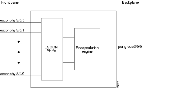
Figure 2-1 shows the interfaces for the ESCON aggregation card.
Figure 2-1 ESCON Aggregation Card Interfaces
Esconphy Interfaces
The esconphy interfaces are located on the front panel of the ESCON aggregation cards. Each ESCON aggregation card has 10 esconphy interfaces. The ESCON aggregation card aggregates the signals from the esconphy interfaces into a single 2.5-Gbps signal and sends it to the portgroup interface on the backplane side of the card. The esconphy is an uncolored interface that carries ESCON physical layer signals. This interface does not terminate layer 2 or layer 3 protocol operations.
The naming convention for the esconphy interfaces on the ESCON aggregation card is as follows:
esconphy slot/subcard/port
Portgroup Interfaces
This logical interface represents the aggregation of multiple packet streams from the client side esconphy interfaces. The result is a a 2.5-Gbps aggregate packet stream. The portgroup interface connects the interfaces on the front panel to the switch fabrics. A logical interface representing the aggregation of up to 10 ESCON client signals.
The naming convention for the portgroup interfaces is as follows:
portgroup slot/subcard/port
Each ESCON aggregation card has only one portgroup interface.
8-Port FC/GE Aggregation Card Interfaces
The 8-port FC/GE aggregation card has two types of interfaces:
•
•
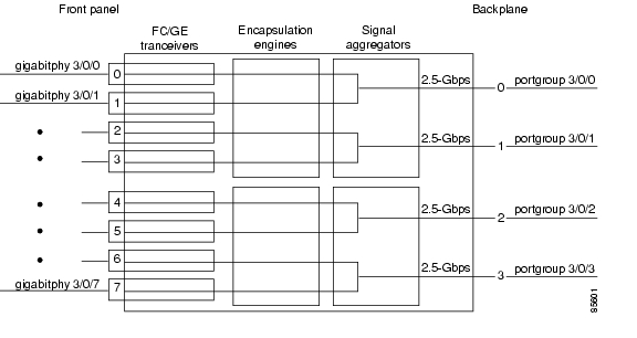
Figure 2-2 shows the interfaces for the 8-port FC/GE aggregation card.
Figure 2-2 8-Port FC/GE Aggregation Card Interfaces
Gigabitphy Interfaces
The gigabitphy interfaces are located on the front panel of the 8-port FC/GE aggregation cards. Each 8-port FC/GE aggregation card uses eight individually programmable SFPs for the gigabitphy interfaces. The 8-port FC/GE aggregation card aggregates the signals from adjoining pairs of gigabitphy interfaces (0 and 1, 2 and 3, 4 and 5, and 6 and 7, see Figure 2-2) into a four 2.5-Gbps signals and sends them to the portgroup interfaces on the backplane side of the card.
The naming convention for the gigabitphy interfaces on the 8-port FC/GE aggregation card is as follows:
gigabitphy slot/subcard/port
Portgroup Interfaces
This logical interface represents the aggregation of multiple packet streams from the client side gigabit interfaces. The result is a a 2.5-Gbps aggregate packet stream. The portgroup interface connects the interfaces on the front panel to the switch fabrics. A logical interface representing the aggregation of up to two FC or GE client signals.
The naming convention for the portgroup interfaces is as follows:
portgroup slot/subcard/port
Each 8-port FC/GE aggregation card has four portgroup interfaces.
2.5-Gbps ITU Trunk Card Interfaces
The 2.5-Gbps ITU trunk cards have four types of interfaces:
•
•
•
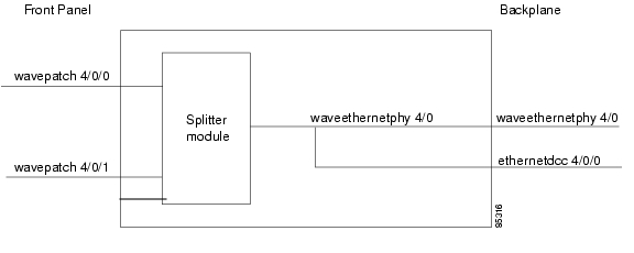
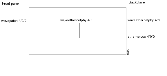
Figure 2-3 shows the interfaces for the splitter 2.5-Gbps ITU trunk card. Figure 2-4 shows the interfaces for the nonsplitter 2.5-Gbps ITU trunk card.
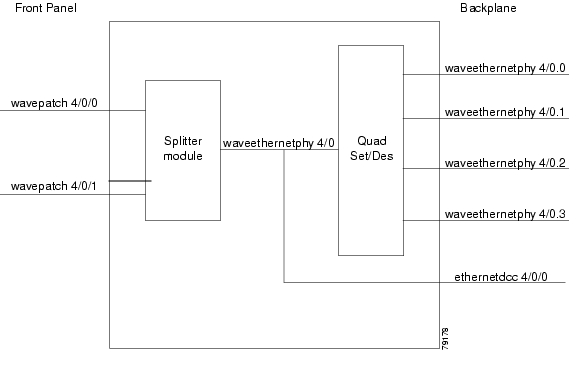
Figure 2-3 Splitter 2.5-Gbps ITU Trunk Card Interfaces
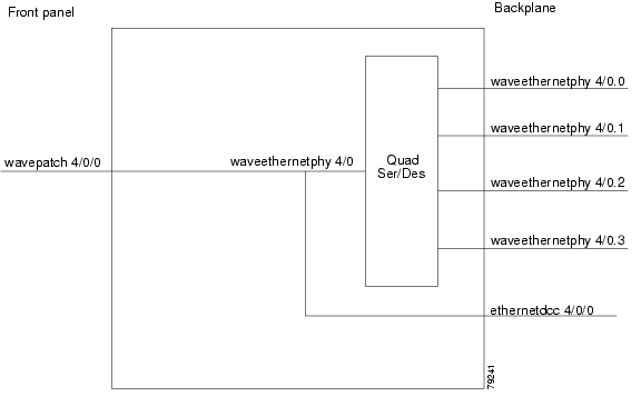
Figure 2-4 Nonsplitter 2.5-Gbps ITU Trunk Card Interfaces
Ethernetdcc Interfaces
The ethernetdcc interfaces provide the communication path for the in-band message channel OAM messages between the 2.5-Gbps ITU trunk card and the CPU switch modules. The ethernetdcc interface connects the switch fabrics to the waveethernetphy interface.
The naming convention for ethernetdcc interfaces is as follows:
ethernetdcc slot/subcard/port
Each card has one ethernetdcc interface.
Waveethernetphy Interfaces
The waveethernetphy interface corresponds to the laser on the 2.5-Gbps ITU trunk cards. The waveethernetphy interface connects to the wavepatch interface on the front panel. The waveethernetphy interface ITU signal carries a 2.5-Gbps physical layer signal. It does not terminate layer 2 or layer 3 protocol operations.
The naming convention for the waveethernetphy interfaces is as follows:
waveethernetphy slot/subcard
Each 2.5-Gbps ITU trunk card has one waveethernetphy interface.
Wavepatch Interfaces
The wavepatch interface is on the front panel of the 2.5-Gbps ITU trunk card. The waveethernetphy interface connects to the wavepatch interface on the backplane side. The mux/demux filter interface connects to the wavepatch interface on the front panel side.
A splitter 2.5-Gbps ITU trunk card has two wavepatch interfaces. A nonsplitter 2.5-Gbps ITU trunk card has only one wavepatch interface.
The wavepatch interface operational state reflects the operational state of the corresponding waveethernetphy interface. If the waveethernetphy interface is operationally down, the corresponding wavepatch interface is operationally down. Conversely, if the waveethernetphy interface is operationally up, then the wavepatch interface is up. However, the administrative states of the waveethernetphy and wavepatch interfaces are independently tracked.
The naming convention for wavepatch interface is as follows:
wavepatch slot/subcard/port
10-Gbps ITU Trunk Card Interfaces
The 10-Gbps ITU trunk cards have four types of interfaces:
•
•
•
•
Figure 2-5 shows the interfaces for the splitter 10-Gbps ITU trunk card. Figure 2-6 shows the interfaces for the nonsplitter 10-Gbps ITU trunk card.
Figure 2-5 Splitter 10-Gbps ITU Trunk Card Interfaces
Figure 2-6 Nonsplitter 10-Gbps ITU Trunk Card Interfaces
Ethernetdcc Interfaces
The ethernetdcc interfaces provide the communication path for the in-band message channel OAM messages between the 10-Gbps ITU trunk card and the CPU switch modules. The ethernetdcc interface connects the switch fabrics to the waveethernetphy interface.
The naming convention for ethernetdcc interfaces is as follows:
ethernetdcc slot/subcard/port
Each card has one ethernetdcc interface.
Waveethernetphy Interfaces
The waveethernetphy interfaces correspond to the laser on the 10-Gbps ITU trunk cards. The waveethernetphy interface connects the four waveethernetphy subinterfaces on the backplane side of the 10-Gbps ITU trunk card to the wavepatch interface on the front panel. The waveethernetphy interface ITU signal carries up to four 2.5-Gbps physical layer signals. It does not terminate layer 2 or layer 3 protocol operations.
The naming convention for the waveethernetphy interfaces is as follows:
waveethernetphy slot/subcard
Each 10-Gbps ITU trunk card has one waveethernetphy interface.
Waveethernetphy Subinterfaces
The waveethernetphy subinterfaces are located on the backplane side of the10-Gbps ITU trunk cards. The waveethernetphy interface connects the switch fabric to the waveethernetphy interface. Each waveethernetphy subinterface can handle 2.5 Gbps of data traffic.
The naming convention for the waveethernetphy subinterfaces is as follows:
waveethernetphy slot/subcard.subinterface
Each 10-Gbps ITU trunk card has four waveethernetphy subinterfaces.
Wavepatch Interfaces
The wavepatch interfaces are on the front panel of the 10-Gbps ITU trunk card. The waveethernetphy interfaces connect to the wavepatch interfaces on the backplane side. The mux/demux filter interfaces connect to the wavepatch interface on the front panel side.
A splitter10-Gbps ITU trunk card has two wavepatch interfaces. An nonsplitter10-Gbps ITU trunk card has only one wavepatch interface.
The wavepatch interface operational state reflects the operational state of the corresponding waveethernetphy interface. If the waveethernetphy interfaces are operationally down, the corresponding wavepatch interfaces are operationally down. Conversely, if the waveethernetphy interfaces are operationally up, then the wavepatch interfaces are up. However, the administrative states of the waveethernetphy and wavepatch interfaces are independently tracked.
The naming convention for wavepatch interfaces is as follows:
wavepatch slot/subcard/port
10-Gbps Uplink Card Interfaces
The 10-Gbps uplink cards have three types of interfaces:
•
•
•
Figure 2-7 shows the interfaces for the 10-Gbps uplink card.
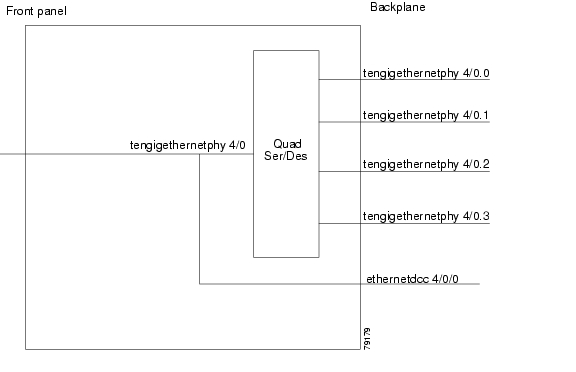
Figure 2-7 10-Gbps Uplink Card Interfaces
Ethernetdcc Interfaces
The in-band message channel OAM messages for inband management are sent and received by the CPU switch module through the ethernetdcc interfaces. The ethernetdcc interface connects to the switch fabrics on the backplane side and the waveethernetphy interface on the front panel side.
The naming convention for ethernetdcc interfaces is as follows:
ethernetdcc slot/subcard/port
Each 10-Gbps uplink card has one ethernetdcc interface.
Tengigethernetphy Interfaces
The tengigethernetphy interfaces correspond to the laser on the 10-Gbps uplink cards. The tengigethernetphy interface connects to the tengigethernetphy subinterface on the backplane side of the 10-Gbps uplink card and to the wavepatch interface on the front panel side. This is an uncolored interface that carries 10-Gigabit Ethernet. This interface does not terminate Layer 2 or Layer 3 protocol operations.
The naming convention for the tengigethernetphy interfaces is as follows:
tengigethernetphy slot/subcard
Each 10-Gbps uplink card has one tengigethernetphy interface.
Tengigethernetphy Subinterfaces
The tengigethernetphy interfaces are the backplane interfaces on the10-Gbps uplink cards. The tengigethernetphy interface connects to the switch fabric.
The naming convention for the tengigethernetphy subinterfaces is as follows:
tengigethernetphy slot/subcard.subinterface
Each 10-Gbps uplink card has four tengigethernetphy subinterfaces.
Transponder Line Card Interfaces
The transponder line cards have three types of interfaces:
•
•
•
Figure 2-8 shows the interfaces for the transponder line card.
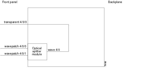
Figure 2-8 Transponder Line Card Interfaces
Transparent Interfaces
The transparent interfaces are located on the front panel of the transponder line cards. The interface does not terminate the protocol, hence the term transparent. Also, transparent applies to transparency with regard to networking protocols. The transparent interface connects to the wave interface on the backplane side of the transponder line card.
The naming convention for the transparent interfaces is as follows:
transparent slot/subcard/port
Each transponder line card has one transparent interface.
Wave Interfaces
The wave interface corresponds to the laser on the transponder line card that generates the channel. The wave interface electrically connects to the transparent interface on the front panel and optically connects to two wavepatch interfaces on a splitter card, or to one wavepatch interface on a nonsplitter card, on the ITU side.
The naming convention for wave interfaces is as follows:
wave slot/subcard
Each transponder line card has one wave interface.
Wavepatch Interfaces
The wavepatch interface is the interface on the front panel that connects to the filter interfaces on the OADM modules. The wave interfaces on the backplane side of the transponder line cards connect to the wavepatch interfaces.
Splitter transponder line cards have two wavepatch interfaces. Nonsplitter transponder line cards have only one wavepatch interface.
The wavepatch interface operational state reflects the operational state of the corresponding wave interface. If the wave interfaces are operationally down, the corresponding wavepatch interfaces are operationally down. Conversely, if the wave interfaces are operationally up, then the wavepatch interfaces are up. However, the administrative states of the wave and wavepatch interfaces are independently tracked.
The naming convention for wavepatch interfaces is as follows:
wavepatch slot/subcard/port
OADM Module Interfaces
The OADM modules can have four types of interfaces:
•
•
•
•
Figure 2-9 shows the interfaces for the OADM module.
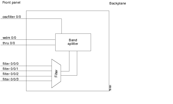
Figure 2-9 OADM Module Interfaces
Filter Interfaces
The filter interface connects to a wavepatch interface on either a transponder line card, a 2.5-Gbps ITU trunk card, or a 10-Gbps ITU trunk card. Each filter interface corresponds to an individual wavelength filter. The filter interface connects a wavepatch interface to a wdm interface on the same OADM module.
The naming convention for filter interfaces is as follows:
filter slot/subcard/port
Each OADM module has four filter interfaces.
Oscfilter Interfaces
The OADM modules can support an optional OSC with an oscfilter interface. This interface connects to the wave interface on an OSC card.
The naming convention for the OSC interface on an OADM module is as follows:
oscfilter slot/subcard
Wdm Interfaces
The wdm interface is the interface on the OADM module that receives the DWDM signal containing wavelengths to be dropped, or transmits the DWDM signal with added wavelengths. It represent the pairs of fibers (Tx and Rx) on the front panel of an OADM module. The wdm interface connects either to a wdm interface on another network node, or to a thru interface on an OADM module on a different chassis in the same network node.
The naming convention for wdm interfaces is as follows:
wdm slot/subcard
Thru Interfaces
The thru interface is the interface on the OADM module that sends the DWDM signal to, or receives it from, another OADM module without altering it. It represents the pairs of fibers (Tx and Rx) on the front panel of an OADM module. The thru interface connects to the thru interface on the OADM module in the other subslot on the same chassis, or to a wdm interface on an OADM module on another chassis in the same network node.
The naming convention for thru interfaces is as follows:
thru slot/subcard
PSM Interfaces
The PSM (protection switch module) provides trunk fiber protection on the Cisco ONS 15530. The PSM has two types of interfaces:
•
•
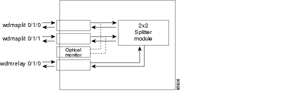
Figure 2-10 shows the interfaces for the PSM.
Figure 2-10 PSM Interfaces
Wdmrelay Interfaces
The wdmrelay interface is a passive interface that represents a pair of fibers and connects the PSM to the wdm interface on the OADM module.
The naming convention for wdmrelay interfaces is as follows:
wdmrelay slot/subcard/port
Wdmsplit Interfaces
The wdmsplit interface represents a pair of fibers and connects the trunk fiber. The PSM has two wdmsplit interfaces, one for the west direction and one for the east.
The naming convention for wdmsplit interfaces is as follows:
wdmsplit slot/subcard/port
The west interface is wdmsplit slot/subcard/0 and the east interface is wdmsplit slot/subcard/1.
OSC Card Interfaces
The optional OSC provides out-of-band management communications among the Cisco ONS 15530 systems in a network. The OSC is separate from the 32 data channels. The OSC card has one interface, the wave interface.
Wave Interfaces
The wave interface corresponds to the laser on the OSC card that generates the channel. The shelf can have up to two OSCs in the OSC motherboard, one per OADM module.
The naming convention for the OSC interface on an OADM module is as follows:
wave slot/subcard
CPU Switch Module Interfaces
The CPU switch modules have two types of interfaces:
•
•
NME Interfaces
Each CPU switch module has a Fast Ethernet interface, called an NME, for network management purposes. The NME interface on the active CPU switch module is named fastethernet 0 and the NME interface on the standby CPU switch module is named as fastethernet-sby 0.
Each NME interface has a unique MAC address. Also, you must configure each NME interface with a unique IP address. After a processor switchover, when the standby CPU switch module takes over as active, the IP and MAC addresses of the standby CPU switch module are reinitialized to those of the active CPU switch module.
Note
Auxiliary Port Interfaces
Each CPU switch module has an auxiliary port interface. You can use this interface for modem connections. This interface is named aux 0. The DUART provides two UART channels, both of which connects to an RJ-45 connector on the front panel as the console and auxiliary ports. Typically, the console port connects to a console for configuring, controlling, or debugging the CPU switch module.
WB-VOA Card Interfaces
WB-VOA (wide-band variable optical attenuator) modules have two types of interfaces:
•
•
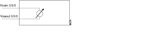
Figure 2-11 shows the interfaces for the single WB-VOA module.
Figure 2-11 Single WB-VOA Module Interfaces
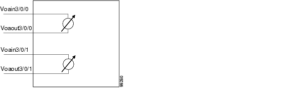
Figure 2-12 shows the interfaces for the dual WB-VOA module.
Figure 2-12 Dual WB-VOA Module Interfaces
Voain Interfaces
The voain interface is the input interface on a WB-VOA module. It accepts the signal to be attenuated.
The naming convention for the voain interface on a VOA card is as follows:
voain slot/subcard/port
Voaout Interfaces
The voaout interface is the output interface on a WB-VOA module. It transmits the attenuated signal.
The naming convention for the voaout interface on a VOA module is as follows:
voaout slot/subcard/port
PB-OE Module Interfaces
PB-OE (per-band optical equalizer) modules have four types of interfaces:
•
•
•
•
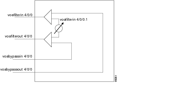
Figure 2-13 shows the interfaces for the single PB-OE module.
Figure 2-13 Single PB-OE Module Interfaces
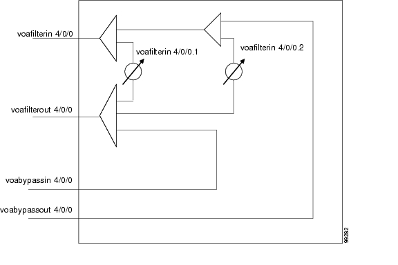
Figure 2-14 shows the interfaces for the dual PB-OE module.
Figure 2-14 Dual PB-OE Module Interfaces
Voafilterin Interfaces
The voafilterin interface identifies the physical port on the PB-OE that accepts the incoming DWDM signal for power equalization.
The naming convention for the voafilterin interface on a PB-OE module is as follows:
voafilterin slot/subcard/port
Voafilterin Subinterfaces
The voafilterin subinterface identifies the attenuator within the PB-OE module.
The naming convention for the voafilterin interface on a PB-OE module is as follows:
voafilterin slot/subcard/port.subinterface
Single band PB-OE modules have one voafilterin subinterface. Dual band PB-OE modules have two voafilterin subinterfaces.
Voafilterout Interfaces
The voafilterout interface sends the DWDM signal to the EDFA (erbium-doped fiber amplifier) or the next node in the network topology.
The naming convention for the voafilterout interface on a PB-OE module is as follows:
voafilterout slot/subcard/port
Voabypassout Interfaces
The voabypassout interface carries that portion of the signal not attenuated by the PB-OE module. This interface connects to another VOA module input interface (either a voain interface or a voafilterin interface) where the signal is further attenuated.
The naming convention for the voabypassout interface on a PB-OE module is as follows:
voabypassout slot/subcard/port
Voabypassin Interfaces
The voabypassin interface carries that portion of the signal attenuated on other modules. This interface connects to another VOA module output interface (either a voaout interface or a voafilterout interface) where the signal was attenuated.
The naming convention for the voabypassin interface on a PB-OE module is as follows:
voabypassin slot/subcard/port
Configuration Overview
To configure your Cisco ONS 15530 systems and network, perform the following steps:
Step 1
For detailed information about the hardware components, refer to the Cisco ONS 15530 Hardware Installation Guide. For detailed information on system planning and design, refer to the Cisco ONS 15530 Planning Guide.
Step 2
For detailed information on hardware configuration rules, refer to the Cisco ONS 15530 Planning Guide.
Step 3
For detailed information on configuring the NME port, see Chapter 3, "Initial Configuration."
Step 4
For detailed information on cabling cards and modules, refer to the Cisco ONS 15530 Planning Guide. For information on configuring cross connections, see the "Configuring Cross Connections" section on page 4-8.
Step 5
For detailed information on configuring these interfaces, see Chapter 4, "Configuring ESCON Aggregation Card Interfaces," Chapter 5, "Configuring 8-Port FC/GE Aggregation Card Interfaces," and Chapter 7, "Configuring Trunk and Uplink Card Interfaces."
Step 6
For detailed information on transponder line card interface configuration, see Chapter 6, "Configuring Transponder Line Card Interfaces."
Step 7
For detailed information on VOA module interface configuration, see Chapter 8, "Configuring VOA Module Interfaces."
Step 8
For detailed information on configuring APS, see Chapter 10, "Configuring APS."
Step 9
For detailed information on CPU switch module redundancy, see the "About CPU Switch Module Redundancy" section on page 3-11.
Step 10
For detailed information on configuring IP connectivity on the OSC, see the "Configuring IP on the OSC" section on page 12-8. For information on configuring IP connectivity via the in-band message channel, see the "Configuring IP on Ethernetdcc Interfaces for the In-Band Message Channel" section on page 12-12.
Step 11
For detailed information on network monitoring, see Chapter 12, "Monitoring Your Network Topology."
![]()
![]()
![]()
![]()
![]()
![]()
![]()
![]()
Posted: Wed Sep 22 23:48:05 PDT 2004
All contents are Copyright © 1992--2004 Cisco Systems, Inc. All rights reserved.
Important Notices and Privacy Statement.