|
|

Table Of Contents
Configuring 8-Port FC/GE Aggregation Card Interfaces
About the 8-Port FC/GE Aggregation Card
Configuring 8-Port FC/GE Aggregation Card Interfaces
Displaying the 8-Port FC/GE Aggregation Card Interface Configuration
About Latency and Transmit Buffers
Configuring Transmit Buffer Size for FC, FICON, and ISC
Displaying Transmit Buffer Configuration
Displaying the Cross Connection Configuration
Displaying the Alarm Threshold Configuration
Configuring 8-Port FC/GE Aggregation Card Interfaces
This chapter describes how to configure 8-port Fibre Channel/Gigabit Ethernet aggregation cards on the Cisco ONS 15530. This chapter includes the following sections:
•
About the 8-Port FC/GE Aggregation Card
•
•
•
•
•
Note
About the 8-Port FC/GE Aggregation Card
The 8-port FC/GE aggregation card uses SFP (small form-factor pluggable) optical transceivers to provide up to eight configurable client interfaces. Each interface can be configured in the CLI (command-line interface) for FC (Fibre Channel), FICON (fiber connection), GE (Gigabit Ethernet), or ISC-3 (InterSystem Channel) links compatibility mode traffic.
To configure the 8-port FC/GE aggregation card on the Cisco ONS 15530, perform the following steps:
Step 1
Step 2
Step 3
Step 4
Step 5
Note
Note
Protocol Monitoring
For GE traffic, the Cisco ONS 15530 monitors the following conditions on the 8-port FC/GE aggregation card:
•
•
•
•
•
•
•
For FC and FICON traffic, the system monitors the following conditions on the 8-port FC/GE aggregation card:
•
•
•
•
•
•
•
•
•
•
For ISC-3 compatibility mode traffic, the system monitors the following conditions on the 8-port FC/GE aggregation card:
•
•
Support for FC Port Types
The 8-port FC/GE aggregation card supports the following FC port types, with or without the buffer credit distance extension feature enabled:
•
•
•
•
•
Note
Examples of valid topologies where you can put a Cisco ONS 15530 with an 8-port FC/GE aggregation card in the middle to extend distance include the following:
•
•
•
•
•
Arbitrated loop topology is not supported by the 8-port FC/GE aggregation card. The arbitrated loop port types not supported include:
•
•
•
So any combination of above port types are not supported.
Configuring 8-Port FC/GE Aggregation Card Interfaces
The 8-port FC/GE aggregation card has two types of interfaces: eight gigabitphy interfaces on the client side and four portgroup interfaces on the trunk side.
To configure the 8-port FC/GE aggregation card interfaces, perform the following tasks, starting in global configuration mode:
Step 1
Switch(config)# interface gigabitphy slot/0/port
Switch(config-if)#
Specifies an interface to configure and enters interface configuration mode.
Step 2
Switch(config-if)# encapsulation {fibrechannel [ofc {enable | disable}] | ficon [ofc {enable | disable} | gigabitethernet | sysplex isc compatibility}
Configures the interface as either FC, FICON, GE, or ISC-3 compatibility mode. The default mode for OSC is disabled.
Step 3
Switch(config-if)# cdl flow identifier number
Specifies the flow identifier for the signal. The range is 0 to 174.
Step 4
Switch(config-if)# laser control forward enable
Enables forward laser control on the interface. The default is disabled. (Optional)
You must enable FLC at both ends for FLC to take effect when loss of light occurs. This card uses end-to-end FLC (E2EFLC). For more information on FLC, see the "About Laser Shutdown" section on page 6-14
Step 5
Switch(config-if)# flow control
Enables buffer credits when the interface is encapsulated for Fibre Channel traffic. The default is disabled. (Optional)
Step 6
Switch(config-if)# negotiation auto
Enables autonegotiation between the 8-port FC/GE aggregation card and the client equipment when the interface is encapsulated for Gigabit Ethernet traffic. The default is disabled. (Optional)
Note
Step 7
Switch(config-if)# no shutdown
Enables the interface.
Step 8
Switch(config-if)# exit
Switch(config)#
Returns to global configuration mode.
Repeat Step 1 through Step 8 for the other gigabitphy interfaces on the 8-port FC/GE aggregation card.
Caution
Example
The following example shows how to configure 8-port FC/GE aggregation card interfaces:
Switch(config)# interface gigabitphy 3/0/0Switch(config-if)# encapsulation fibrechannelSwitch(config-if)# cdl flow identifier 30Switch(config-if)# no shutdownSwitch(config-if)# exitDisplaying the 8-Port FC/GE Aggregation Card Interface Configuration
To display the configuration of 8-port FC/GE aggregation card interfaces, use the following EXEC command:
show interfaces {gigabitphy | portgroup} slot/subcard/port
Displays the interface configuration.
Example
The following example shows how to display the configuration of a gigabitphy interface configured as GE:
Switch# show interfaces gigabitphy 2/0/0GigabitPhy2/0/0 is up, line protocol is upOptical Transceiver:Single ModeSignal quality:GoodEncapsulation:GigabitEthernetTime of last "encapsulation" change 00:47:39Forward laser control:OffFlow-identifier:20Loopback not setConfigured threshold Group(s):txcrc-sf6Threshold monitored for:tx-crcSF set value:10e-6 (994 in 1 secs)Received Frames:39489Received Bytes:59233500Transmit Frames:39489Transmit Bytes:59233500Code violation and running disparity error count( 8b10b cvrd):0RX CRC errors:39489TX CRC errors:39489Giant Packets:0Runt Packets:05 minute input rate 0 bits/sec, 0 frames/sec5 minute output rate 0 bits/sec, 0 frames/secTransmit Buffer size is 256 bytesHardware is gige_fc_phy_portThe following example shows how to display the configuration of a gigabitphy interface configured as FC:
Switch# show interfaces gigabitphy 2/0/1GigabitPhy2/0/1 is down, line protocol is downOptical Transceiver:Single ModeSignal quality:Loss of lightEncapsulation:Fibre channel Rate:1G Ofc:offflow control:disabledTime of last "encapsulation" change 00:47:46Forward laser control:OffFlow-identifier:21Loopback not setConfigured threshold Group(s):txcrc-sf3Threshold monitored for:tx-crcSF set value:10e-3 (83333 in 1 secs)Received Frames:0Received Bytes:0Transmit Frames:0Transmit Bytes:0Code violation and running disparity error count( 8b10b cvrd):0RX CRC errors:0Link Failures:0Loss of Sync:0Loss of Light:0Sequence Protocol Error count:0Invalid Transmission Word count:05 minute input rate 0 bits/sec, 0 frames/sec5 minute output rate 0 bits/sec, 0 frames/secTransmit Buffer size is 256 bytesHardware is gige_fc_phy_portThe following example shows how to display the configuration of a portgroup interface:
Switch# show interfaces portgroup 2/0/0Portgroup2/0/0 is up, line protocol is upReceived Frames:1472937898Transmit Frames:1472937897Giant/Runt Frame count:0Code violation and running disparity error count(cvrd):30311179128Number of times SF threshold exceeded:0CDL HEC error count:0SII Mismatch error count:0Hardware is gefc_portgroupAbout Latency and Transmit Buffers
The 8-port FC/GE aggregation card adds latency to the transmission of FC, FICON, and ISC traffic depending on the services configured. Table 5-1 shows the various configurations on the transmitting node and the FC, FICON, and ISC latency values, both the time in microseconds and the equivalent distance in kilometers (in parentheses).
Note
Table 5-1 FC, FICON, and ISC Latency Values for 8-Port FC/GE Aggregation Cards
FC/FICON/ISC only on the 2.5-Gbps aggregated signal carried over a 2.5-Gbps ITU trunk card
18.8 microseconds
(3.8 km)
FC/FICON/ISC only on a 2.5-Gbps aggregated signal carried over a 10-Gbps ITU trunk card
19.9 microseconds
(4.0 km)
FC/FICON/ISC only on a 2.5-Gbps aggregated signal mixed with GE on the same 10-Gbps ITU trunk card
22.2 microseconds
(4.4 km)24.8 microseconds
(5.0 km)36.3 microseconds
(7.3 km)FC/FICON/ISC and GE on the same 2.5-Gbps aggregated signal carried over a 2.5-Gbps ITU trunk card
27.9 microseconds
(5.6 km)47.1 microseconds
(9.4 km)83.6 microseconds
(16.7 km)FC/FICON/ISC and GE on the same 2.5-Gbps aggregated signal carried over a 10-Gbps ITU trunk card
39.2 microseconds
(7.8 km)77.1 microseconds
(15.4 km)151.1 microseconds
(30.2 km)
1 The latency values are based on configuration of correct transmit buffer sizes as described in Table 5-2.
The transmit buffer on the receiving node compensates for the packet jitter effects due to service multiplexing on the trunk. You must correctly configure the size of this transmit buffer to ensure that no buffer underflow or overflow occurs. Symptoms of an improperly configured transmit buffer on the gigabitphy interface include CRC errors, frame drops, and transmission word errors detected by the receiving FC, FICON, or ISC client node.
Note
Configuring Transmit Buffer Size for FC, FICON, and ISC
To configure the transmit buffer on the receiving node, perform the following steps, starting in global configuration mode:
Table 5-2 provides transmit buffer settings for various configurations possible on the remote node.
Note
Example
The following example shows how to configure the transmit buffer size on the receiving node:
Switch(config)# interface gigabitphy 2/0/0Switch(config-if)# shutdownSwitch(config-if)# tx-buffer size 1280Switch(config-if)# no shutdownDisplaying Transmit Buffer Configuration
To display the transmit buffer configuration, use the following EXEC command:
Example
The following example shows how to display the transmit buffer configuration:
Switch# show interfaces gigabitphy 2/0/0GigabitPhy2/0/0 is up, line protocol is upOptical Transceiver: Multi-ModeSignal quality: GoodEncapsulation: GigabitEthernetTime of last "encapsulation" change 3d18hForward laser control: OffFlow-identifier: 20Loopback not setThreshold monitored for: NoneReceived Frames: 0Received Bytes: 0Transmit Frames: 0Transmit Bytes: 0Code violation and running disparity error count( 8b10b cvrd): 760759RX CRC errors: 0TX CRC errors: 0Giant Packets: 0Runt Packets: 05 minute input rate 0 bits/sec, 0 frames/sec5 minute output rate 0 bits/sec, 0 frames/secTransmit Buffer size is 256 bytesMTU size is 10232 bytesHardware is gige_fc_phy_portAbout Cross Connections
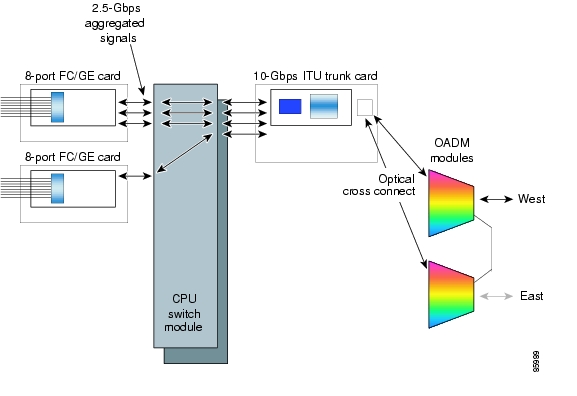
The client signal follows a path of interface optical cross connections through the Cisco ONS 15530. Figure 5-1 shows an example of cross connections. Knowing the path of a signal through the shelf helps with system management and troubleshooting.
Figure 5-1 Optical Cross Connection Example
Configuring Cross Connections
The aggregated signals from the 8-port FC/GE aggregation cards pass through the switch fabric to the 2.5-Gbps ITU trunk card, 10-Gbps ITU trunk card, or the 10-Gbps uplink card. To establish a cross connection through the switch fabric, perform the following steps, beginning in global configuration mode:
Switch(config)# connect interface1 interface2
Creates a cross connection between two interfaces through the switch fabric.
Examples
The following example shows how to configure a cross connection between an 8-port FC/GE aggregation card and a 2.5-Gbps ITU trunk card:
Switch(config)# connect portgroup 2/0/0 waveethernetphy 3/0The following example shows how to configure a cross connection between an 8-port FC/GE aggregation card and a 10-Gbps ITU trunk card:
Switch(config)# connect portgroup 2/0/0 waveethernetphy 3/0.1The following example shows how to configure a cross connection between an 8-port FC/GE aggregation card and a 10-Gbps uplink card:
Switch(config)# connect portgroup 2/0/0 tengigethernetphy 3/0.1Displaying the Cross Connection Configuration
To display the cross connection configuration, use the following privileged EXEC command:
show connect [edge | intermediate [sort-channel | interface interface]]
Displays the signal cross connection configuration through the system.
Examples
The following example shows the cross connections:
Switch# show connectIndex Client Intf Trunk Intf Kind C2TStatus T2CliStatus----- --------------- --------------- ----------- ---------- ---------15 Port3/0/0 WaveE8/0.1 Provisioned Up UpThe following example shows the intermediate cross connections:
Switch# show connect intermediateclient/ wave wave wdmwave client patch filter trk channel------------ ------------ ------- ------ ----- -------Giga2/0/0 TenGE7/0 Giga2/0/1 TenGE7/0About Alarm Thresholds
You can configure thresholds on the 8-port FC/GE aggregation card interfaces that issue alarm messages to the system if the thresholds are exceeded.
Every second, the monitoring facility updates the counters that correspond to the alarm thresholds. When the signal degrades, or fails entirely, the system issues alarms to the console. These alarms can help isolate failures in the system and in the network.
You can configure more than one threshold list on an interface. The threshold lists cannot have overlapping counters so that only one counter is set for the interface. Also, the threshold list name cannot begin with the text string "default" because the it is reserved for use by the system.
Configuring Alarm Thresholds
To configure alarm thresholds on the 8-port FC/GE aggregation card interfaces, perform the following steps, beginning in global configuration mode:
Step 1
Switch(config)# threshold-list name
Switch(config-t-list)#
Creates or selects the threshold list to configure and enters threshold list configuration mode.
Note
Step 2
Switch(config-t-list)# notification-throttle timer seconds
Configures the SNMP notification timer. The default value is 5 seconds. (Optional)
Step 3
Switch(config-t-list)# threshold name {cvrd | cdl hec | crc | sonet-sdh section cv | tx-crc} {failure | degrade} [index value]
Switch(config-threshold)#
Specifies a threshold type to modify and enters threshold configuration mode.
Step 4
Switch(config-threshold)# value rate value
Specifies the threshold rate value. This value is the negative power of 10 (10-n).
Step 5
Switch(config-threshold)# description text
Specifies a description of the threshold. The default value is the null string. (Optional)
Step 6
Switch(config-threshold)# exit
Switch(config-t-list)#
Returns to threshold list configuration mode.
Repeat Step 3 through Step 6 to configure more thresholds in the threshold list.
Step 7
Switch(config-t-list)# exit
Switch(config)#
Returns to global configuration mode.
Step 8
Switch(config)# interface interface
Switch(config-if)#
Selects the interface to configure and enters interface configuration mode.
Step 9
Switch(config-if)# threshold-group name
Configures the threshold list on the interface.
Table 5-3 lists the threshold error rates in errors per second for 8-port FC/GE signals.
Table 5-3 Threshold Values for Monitored Rates for FC/FICON/GE Signals in Errors Per Second
3
83333
1244390
4
58235
124944
5
9423
12499
6
994
1250
7
100
125
8
100
12
9
10
1
1 CRC=cyclic redundancy check
2 CVRD= code violation and running disparity error
Note
Example
The following example shows how to create an alarm threshold list and configure that list for 8-port FC/GE aggregation card interfaces:
Switch# configure terminalSwitch(config)# threshold-list gigabitphy-countersSwitch(config-t-list)# threshold name tx-crc degradeSwitch(config-threshold)# value rate 9Switch(config-threshold)# exitSwitch(config-t-list)# threshold name tx-crc failureSwitch(config-threshold)# value rate 7Switch(config-threshold)# exitSwitch(config-t-list)# exitSwitch(config)# interface gigabitphy 3/0/0Switch(config-if)# threshold-group gigabitphy-countersDisplaying the Alarm Threshold Configuration
To display the configuration of a threshold list and the threshold group for an gigabitphy interface, use the following EXEC commands:
show threshold-list [name]
Displays the threshold group configuration.
show interfaces gigabitphy slot/subcard/slot
Displays the interface configuration.
Examples
The following example shows how to display the configuration of a threshold group:
Switch# show threshold-list gigabitphy-countersThreshold List Name: gigabitphy-countersNotification throttle timer : 5 (in secs)Threshold name : CRC Severity : DegradeValue : 10e-9APS Trigger : Not setThreshold name : CRC Severity : FailureValue : 10e-7APS Trigger : Not setThe following example shows how to display the threshold group information for an interface:
Switch# show interfaces gigabitphy 3/0/0GigabitPhy3/0/0 is up, line protocol is upSignal quality: GoodForward laser control: OffConfigured threshold Group: gigabitphy-countersThreshold monitored for: CRCSF set value: 10e-7 (20 in 1 secs)SD set value: 10e-9 (1 in 5 secs)Received Frames: 0Transmit Frames: 0Code violation and running disparity error count(cvrd): 0Number of times SF threshold exceeded: 0Number of times SD threshold exceeded: 0CRC error count: 0Number of times SF threshold exceeded: 0Number of times SD threshold exceeded: 0Egress Packet Sequence error count: 0Egress Packet Indicated error count: 05 minute input rate 0 bits/sec, 0 frames/sec5 minute output rate 0 bits/sec, 0 frames/secHardware is escon_phy_port
![]()
![]()
![]()
![]()
![]()
![]()
![]()
![]()
Posted: Tue May 17 23:47:44 PDT 2005
All contents are Copyright © 1992--2005 Cisco Systems, Inc. All rights reserved.
Important Notices and Privacy Statement.