|
|

The Catalyst 3900 and Catalyst 5000 support Cisco's ISL technology, which allows you to interconnect your switches over a 100 Mbps connection.
This section contains three different scenarios; one for ISL between two Catalyst 3900s, one for ISL between two Catalyst 5000s with Token Ring modules, and one for ISL between a Catalyst 3900 and a Catalyst 5000 with a Token Ring module.
This chapter provides the following information:
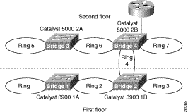
In your company offices, you have two Catalyst 3900s on the first floor and two Catalyst 5000 with Token Ring modules on the second floor. One of the Catalyst 5000s is connected to a router though a Fast Ethernet module. The switches are currently interconnected by normal Token Ring connections. To increase the throughput of the connections between the switches, reduce the number of hops between the endstations and the router, and thereby improve network performance, you have decided to interconnect the switches with ISL.
Figure 10-1 illustrates the initial network configuration. In this configuration, each connection between a switch constitutes another hop in the network. So an endstation attached to Ring 1 must traverse four bridges (or hops) before it reaches the router.
You have added a Token Ring ISL module to each of the Catalyst 3900s. On the Catalyst 5000, ISL is implemented in software and runs on a Fast Ethernet module. One of the Catalyst 5000s has a Fast Ethernet module and you have added a Fast Ethernet module to the other Catalyst 5000.
With switches that are interconnected via ISL, you can use VTP to propagate VLAN information within the management domain. As explained earlier in the "VLAN Trunking Protocol" section of the "Token Ring VLANs and Related Protocols" chapter, a switch can operate in transparent, server, or client mode. For the purposes of this scenario, you have decided to configure one of the Catalyst 3900s to act as a VTP server and to configure the other switches to operate in client mode. Once your switches are joined in a common VTP management domain (which you have decided to call Domain A) the VLAN definitions that are configured on the server switch will be propagated to the client switches. Because you have existing rings in the network that you want to preserve, you must duplicate the definitions of those rings on the switch that is acting as your VTP server. You will be replacing rings 2, 4, and 6 with ISL connections, but will want to preserve the user rings, which are rings 1, 3, 5 and 7.
Currently, the rings are defined as follows:
| Ring Number | VLAN ID | VLAN Name | Parent VLAN |
|---|---|---|---|
1 | 101 | Ring 1 | Bridge 1 |
3 | 103 | Ring 3 | Bridge 2 |
5 | 205 | Ring 5 | Bridge 3 |
7 | 207 | Ring 7 | Bridge 4 |
Also, because ISL allows us to expand the bridge (TrBRF) across switches over the ISL connection, you will be using a single bridge definition on each switch. You have decided to use bridge 1 for your network and eliminate the definitions of bridges 2 through 4.
You have installed an ISL module in slot 1 of the Catalyst 3900 1A and in slot 1 of Catalyst 3900 1B. You have installed a Fast Ethernet module in slot 2 of Catalyst 5000 2A. You already have a Fast Ethernet module installed in slot 2 of Catalyst 5000 2B, which is already connected to the router.
For the physical connections, you have decided to interconnect the devices as follows:
| Switch | Port | Connected to Switch | Port |
|---|---|---|---|
Catalyst 3900 1A | 21 | Catalyst 3900 1B | 21 |
Catalyst 3900 1B | 23 | Catalyst 5000 2B | 2/12 |
Catalyst 5000 2A | 2/1 | Catalyst 5000 2B | 2/11 |
To connect the switches using ISL, you will need to configure an ISL connection between the two Catalyst 3900s, between the two Catalyst 5000s, and between one of the Catalyst 5000s and one of the Catalyst 3900s. You will need to enable the use of VTP in your network, which requires us to assign all the switches to a VTP management domain and configure the switches to act as a server or client.
There is little or no configuration that you need to perform on the actual ISL module. By default, the module is enabled and operates in trunking mode. The ports operate at 100 Mbps and in FDX mode. The only possible transmission mode is store-and-forward. However, you will need to configure a VTP management domain, configure one of the Catalyst 3900s to act as the VTP server, duplicate the definitions of all of the existing TrCRFs on the Catalyst 3900 that is acting as the VTP server, and configure the other to operate in client mode.
To configure Catalyst 3900 1A to be the VTP server, complete the following steps on each switch:
Step 1. On the Catalyst 3900 Main Menu, select Configuration.
Step 2. On the Configuration menu, select VLAN and VTP Configuration.
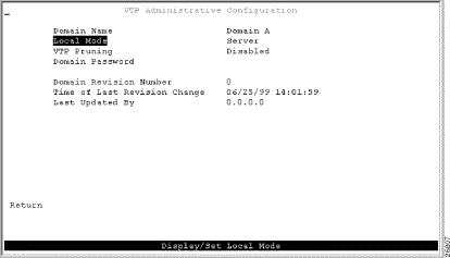
Step 3. On the VLAN and VTP Configuration menu, select VTP Administrative Configuration. The VTP Administrative Configuration panel (Figure 10-2) is displayed.
Step 4. On the VTP Administrative Configuration panel, specify the following:
Step 5. Select Return to save your changes.
Because the configuration of a switch that is operating in VTP server mode is propagated to each of the switches in the VTP management domain that are operating in client mode, you must duplicate the configuration of the existing rings on the switch that is acting as the VTP server before propagating the VLAN information throughout the network. As mentioned before, you have decided to use Bridge 1 (TrBRF 100) as the single bridge in your ISL network. Because the Catalyst 3900 1A contains the definition of Bridge 1, you do not need to configure a new bridge. But as you duplicate the configurations of the other TrCRFs, you will need to change their parent to be Bridge 1.
To configure the TrCRFs, complete the following tasks:
Step 1. On the VTP and VLAN Configuration panel, select VTP VLAN Configuration.
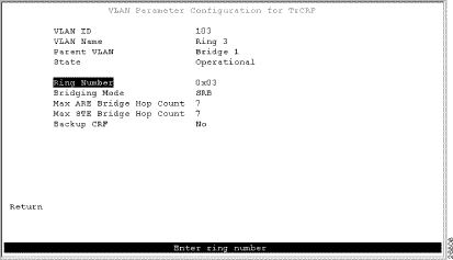
Step 2. On the VTP VLAN Configuration panel, select Add, specify a VLAN ID of 103, and then select TrCRF. The VLAN Parameter Configuration for TrCRF panel (Figure 10-3) is displayed.
Step 3. Specify the following:
Step 4. Select Return to save your changes.
Step 5. On the VTP VLAN Configuration panel, select Add, specify a VLAN ID of 105 , and then select TrCRF. The VLAN Parameter Configuration for TrCRF panel is displayed.
Step 6. Specify the following:
Step 7. Select Return to save your changes.
Step 8. On the VTP VLAN Configuration panel, select Add, specify a VLAN ID of 107, and then select TrCRF. The VLAN Parameter Configuration for TrCRF panel is displayed.
Step 9. Specify the following:
Step 10. Select Return to save your changes.
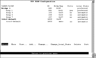
As shown in Figure 10-4, the TrCRFs have been added with Bridge 1 as the parent of each. The Local State indicates whether a VLAN (TrCRF or TrBRF) is used on the local switch. Possible values are not-local, preferred, and automatic.
The new TrCRFs do not have any ports assigned to them on the local switch. Therefore, each has a local mode of Automatic.
To configure Catalyst 3900 1B to participate in the VTP management domain and operate in client mode, complete the following steps on each switch:
Step 1. On the Catalyst 3900 Main Menu, select Configuration.
Step 2. On the Configuration menu, select VLAN and VTP Configuration.
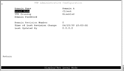
Step 3. On the VLAN and VTP Configuration menu, select VTP Administrative Configuration. The VTP Administrative Configuration panel (Figure 10-5) is displayed.
Step 4. On the VTP Administrative Configuration panel, specify the following:
Step 5. Select Return to save your changes.
Once the cables are connected, within seconds Catalyst 3900 1B should receive VTP advertisements from Catalyst 3900 1A. Once these advertisements are received, the definition of Ring 3 will be overwritten with the new definition in which Bridge 1 is the parent of Ring 3.
On the Catalyst 5000, ISL is implemented in software and can be run on a Fast Ethernet module. For this scenario, you will need to configure both of the Catalyst 5000s to operate in client mode (as one of the Catalyst 3900s is operating a the VTP server). You will also need to configure an ISL connection between one of the Catalyst 3900s and one of the Catalyst 5000s and between the two Catalyst 5000s.
The Catalyst 3900 uses VTP V2. VTP V2 is not downwardly compatible with VTP V1. Therefore, you must configure the Catalyst 5000s to use VTP V2. You must also configure them to participate as clients in your VTP management domain (Domain A). To configure the Catalyst 5000s to be VTP clients, on Catalyst 5000 2A and 2B complete the following steps:
Step 1. At the Catalyst 5000 command prompt, enter enable.
Step 2. At the enable prompt, enter set vtp domain Domain_A mode client v2 enable.
Once the cables are connected, within seconds Catalyst 5000s should receive VTP advertisements from Catalyst 3900 1A. Once these advertisements are received, the definitions of Ring 5 and Ring 7 will be overwritten with the new definitions in which Bridge 1 is the parent of both.
To enable ISL connections on the Catalyst 5000s, you must configure the selected ports on the Fast Ethernet module to act as trunk ports. You must configure the port of Catalyst 5000 2B that connects to the Catalyst 3900 (2/12) to be a trunk port. Because Catalyst 5000 switches can detect that a connection to another Catalyst 5000 has been configured as a trunk, you can configure the other port (2/11) to act as a trunk and the port on Catalyst 5000 2A will detect this and automatically become a trunk port.
To configure ports to be trunk ports, complete the following steps:
Step 1. At the Catalyst 5000 command prompt, enter enable.
Step 2. At the enable prompt, enter set trunk 2/11 on.
Step 3. At the enable prompt, enter set trunk 2/12 on
The Catalyst 5000 Fast Ethernet module is designed to auto-sense the speed and mode of the attached device. The Catalyst 3900 Token Ring ISL module does not support auto-negotiation of speed or mode; it always runs at 100 Mbps in FDX mode. Therefore, when connecting a Catalyst 3900 to a Catalyst 5000 via ISL, you must configure the port of the Catalyst 5000 Fast Ethernet module to operate at the correct speed and mode.
To configure the speed and mode of the Fast Ethernet module on Catalyst 2B, complete the following steps:
Step 1. At the Catalyst 5000 command prompt, enter enable.
Step 2. At the enable prompt, enter set port speed 2/12 100.
Step 3. At the enable prompt, enter set port duplex 2/12 full.
Attach the cables to the switches as described in the "Before Beginning" section. As stated before, once the cables are connected, within seconds client switches should receive VTP advertisements from Catalyst 3900 1A. Once these advertisements are received, the definitions of Ring 3, Ring 5, and Ring 7 will be overwritten with the new definitions in which Bridge 1 is the parent of all.
When you connect two Catalyst switches using ISL, it is important that the STP be used. If you do not use the STP, the ports will be placed in a blocked state and create a loop. The spanning-tree settings differ slightly between the Catalyst 3900 and the Catalyst 5000.
The Catalyst 3900 ISL module supports the STP at both the TrCRF and the TrBRF level. The STP that is run on the ISL link depends on the type of TrCRF:
By default, the Catalyst 3900 runs the IBM STP on the TrBRF. You can configure the TrCRF STP or configure the STP to be automatically determined by the specified bridging mode. TrCRFs with a bridge mode of SRB will run the IEEE STP and TrCRFs with a bridge mode of SRT will run the Cisco STP.
By default, the Catalyst 5000 Token Ring switching module runs the IBM STP on the TrBRF. The STP run on the TrCRFs is determined by the specified bridging mode. TrCRFs with a bridge mode of SRB will run the IEEE STP and TrCRFs with a bridge mode of SRT will run the Cisco STP.
The Catalyst 5000 Token Ring switching module considers the combination of the IBM STP at the TrBRF and the bridge mode of SRT to be incompatible. As a result, if you had configured one of the TrCRFs with a bridge mode of SRT, the Catalyst 500 Token Ring switching module would automatically block the logical port of the TrCRF that is configured for SRT. You can use the show spantree command to view the state of the logical ports. The conflict can be addressed in either of the following ways:
Figure 10-6 and Figure 10-7 illustrate the resulting network configuration.
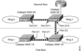
As you can see, rings 2, 4, and 6 have been replaced with the ISL connections. And each switch now contains a ring (TrCRF) that belongs to the same bridge (TrBRF). As a result, logically you now simply have four rings that are joined with the router by a single bridge.

VTP advertisements propagate only certain configuration information. Other configuration settings must be made on the individual switches. The configuration settings that must be made at the switch include the following:
If the VTP information is not being propagated to each of the switches, make sure all switches are configured to be part of the VTP management domain called Domain A. Also, make sure that the Catalyst 5000 switches are running VTP Version 2.
If the Catalyst 3900 does not detect the ISL module when it is inserted (i.e. it does not show up on the listing of modules on the Module Information panel), make sure that you are running revision 3.0(1) or later of the Catalyst 3900 software. You can verify the revision level of the software by selecting Switch Configuration on the Configuration Menu.
If the Catalyst 3900 rejects your attempts to change the VTP mode from Transparent to Client or Server, make sure that you have configured the ring numbers for the associated TrCRFs. The Catalyst 3900 cannot be configured as a VTP client or server if the ring number is set to auto.
![]()
![]()
![]()
![]()
![]()
![]()
![]()
![]()
Posted: Wed Oct 2 03:51:39 PDT 2002
All contents are Copyright © 1992--2002 Cisco Systems, Inc. All rights reserved.
Important Notices and Privacy Statement.