|
|

The Catalyst 3900 and the Catalyst 5000 series provide ATM modules that allow you to connect the switches to an ATM backbone. This chapter provides an example of connecting a Catalyst 3900 and a Catalyst 5000 Token Ring module via an ATM backbone.
This chapter provides the following information:
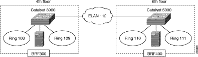
In your company, you have installed a Catalyst 3900 on the fourth floor and a Catalyst 5000 with a Token Ring module in slot 3 on the sixth floor.
There are servers attached to each switch. The users on these floors need to be able to access the servers on both floors. Because your company is in the medical industry (providing telephone support to emergency medical teams), response time is critical. You have decided to utilize the improved performance that ATM offers and to connect your Catalyst Token Ring switches though an ATM backbone.
Figure 9-1 illustrates the initial network configuration. The Catalyst 3900 on the fourth floor contains two TrCRFs (assigned ring numbers 108 and 109) that are joined by a TrBRF that you have named BRF300. The Catalyst 5000 on the sixth floor contains two TrCRFs (assigned ring numbers 110 and 111) that are joined by a TrBRF that you have named BRF400.
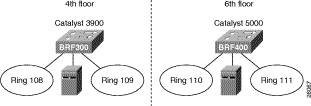
For your ATM backbone, you have installed a Cisco ATM LS1010 switch. You will be using a Catalyst 5000 to provide the LECS, LES, and BUS. For connectivity between the switches, you have installed an Catalyst 3900 ATM module on the Catalyst 3900 and a Catalyst 5000 series ATM module in slot 4 of the Catalyst 5000. In addition, you downloaded the Token Ring LANE support for the Catalyst 5000 from CCO.
When you join the two switches via the ATM backbone, you need to create an ELAN on each switch. The ELAN is essentially a new TrCRF. You have decided to use 112 for the ELAN name as well as the VLAN ID.
To create an ELAN between the two switches, you must configure the ATM module and define an ELAN on both switches.
On the Catalyst 3900, you must configure a TrCRF and an LEC. Also, you must assign the port to the appropriate TrCRF.
To create an ELAN that will span both switches, you must create a new TrCRF (which will also be defined on the Catalyst 5000) and associate it with the TrBRF.
To define the TrCRF, complete the following tasks:
Step 1. On the Catalyst 3900 Main Menu, select Configuration. The Configuration panel is displayed.
Step 2. On the Configuration panel, select VLAN and VTP Configuration. The VLAN and VTP Configuration panel is displayed.
Step 3. On the VLAN and VTP Configuration panel, select VTP VLAN Configuration. The VTP VLAN Configuration is displayed.
Step 4. On the VTP VLAN Configuration panel, select Add.
Step 5. At the prompt, enter a VLAN ID of 112.
Step 6. At the prompt, select TrCRF. The VLAN Parameter Configuration for TrCRF panel (Figure 9-2) is displayed.
Step 7. On the VLAN Parameter Configuration for TrCRF panel, specify:
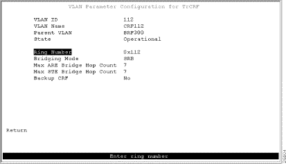
Step 8. Select Return to save your changes.
Next, you must assign the ATM port to the new TrCRF. Before you can do that, the ATM module must be inserted into one of the expansion slots on the Catalyst 3900. If you insert the module into the left slot, the ATM port is assigned a port number of 21. If you insert the module into the right slot, the ATM port is assigned a port number of 25.
To assign the ATM port to TrCRF 112, complete the following tasks:
Step 1. On the Configuration panel, select VLAN and VTP Configuration.The VLAN and VTP Configuration panel is displayed.
Step 2. On the VLAN and VTP Configuration panel, select Local VLAN Port Configuration. The Local VLAN Port Configuration panel is displayed.
Step 3. On the Local VLAN Port Configuration panel, select Change.
Step 4. At the prompt, enter port number 25.
Step 5. Select CRF112 from the list of possible TrCRFs. To select the TrCRF, use your arrow keys to highlight the desired TrCRF, press the space bar to select it, and press Enter to implement your change (Figure 9-3).
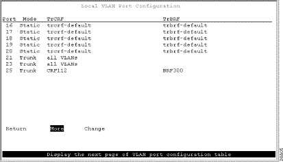
Step 6. Select Return to save your changes.
When you assign the ATM port to a TrCRF, an LEC is automatically created with an ELAN name that is the same as the VLAN name of the TrCRF.
Because the LEC is automatically created and given an ELAN name, you do not need to configure anything for the LEC.
To view the configuration of the LEC, complete the following steps:
Step 1. On the Configuration panel, select Port Configuration and specify the appropriate port number. Because you have installed the ATM module in the right slot, the port number is 25. The ATM Configuration panel is displayed.
Step 2. On the ATM Configuration panel, select ATM LEC Setup. The ATM LEC Setup panel is displayed.
Step 3. On the ATM LEC Setup panel, select LANE Parameters. The LANE Parameters panel (Figure 9-4) is displayed.
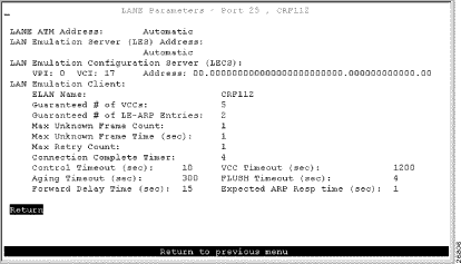
Step 4. Select Return to save your changes.
On the Catalyst 5000, you must configure a TrCRF and an LEC. Because the Catalyst 5000 ATM module provides a trunk port, you do not need to assign the port to the appropriate TrCRF. Trunk ports are automatically associated with LECs as they are configured.
You have decided to use the Catalyst 5000 for the LES and BUS. Therefore, you will also need to configure the ATM module for the LES/BUS support.
When configuring LECs on a Catalyst 5000, remember the following:
The set vlan command assumes that any ring number entered is in hexadecimal. Therefore 0x12 or 12 will be stored as the hexadecimal value 0x12. The name elan_name local-seg-id segment_number command assumes that any value entered for the local-seg-id is in decimal unless it is entered explicitly in hexadecimal. For example, to define a TrCRF with a ring number of 12, you could enter:
set vlan 12 name crf12 type trcrf ring 12 parent 100
or
set vlan 12 name crf12 type trcrf ring 0x12 parent 100
When defining a corresponding LEC, you could enter:
name crf12 local-seg-id 0x12
or
name crf12 local-seg-id 18
as 18 is the decimal equivalent of 0x12.
To define the TrCRF, complete the following steps:
Step 1. At the enable prompt, enter set vlan 112 name crf112 type trcrf ring 112 parent 400 mode srb.
Step 2. To verify the configuration of the new VLAN, enter show vlan.
The output (Figure 9-5) indicates that crf112 has been added. It also shows that brf400 is the parent of the VLAN with the ID of 112.
VLAN Name                             Status    Mod/Ports, Vlans
---- -------------------------------- --------- ----------------------------
1    default                          active    1/1-2
                                                2/1-48
110  crf110                           active    3/1-4
111  crf111                           active    3/5-8
112  crf112                           active
400  brf400                           active    110,111,112
1002 fddi-default                     active
1003 trcrf-default                    active    3/9-16
1004 fddinet-default                  active
1005 trbrf-default                    active    1003

VLAN Type  SAID       MTU   Parent RingNo BrdgNo Stp  BrdgMode Trans1 Trans2
---- ----- ---------- ----- ------ ------ ------ ---- -------- ------ ------
1    enet  100001     1500  -      -      -      -    -        0      0
110  trcrf 100110     4472  300    0x110  -      -    srb      0      0
111  trcrf 100110     4472  300    0x111  -      -    srb      0      0
112  trcrf 100110     4472  300    0x112  -      -    srb      0      0
300  trbrf 100100     4472  -      -      0x3    ibm  -        0      0
400  trbrf 100100     4472  -      -      0x4    ibm  -        0      0
1002 fddi  101002     1500  -      0x0    -      -    -        0      0
1003 trcrf 101003     4472  1005   0xccc  -      -    srb      0      0
1004 fdnet 101004     1500  -      -      0x0    ieee -        0      0
1005 trbrf 101005     4472  -      -      0xf    ibm  -        0      0
To configure the LEC, BUS, and LEC, complete the following steps:
Step 1. Set up the prefix of the ATM Network Service Access Point (NSAP) address for the switch.
Step 2. Start a session to the ATM module that is in slot 4 by entering the session 4 command. You see the following display:
Console> session 4

Trying ATM-4...
Connected to ATM-4.
Escape character is '^]'.
ATM>
Step 3. Obtain the addresses of the LES and LES/BUS for later use by entering the enable command (to enable configuration mode) and the show lane default-atm-addresses command at the ATM prompt. You see the following display:
ATM> enable

ATM#
ATM# show lane default-atm-addresses interface atm0


interface ATM0:
LANE Client:        47.0091810000000061705b7701.00400BFF0010.**
LANE Server:        47.0091810000000061705b7701.00400BFF0011.**
LANE Bus:           47.0091810000000061705b7701.00400BFF0012.**
LANE Config Server: 47.0091810000000061705b7701.00400BFF0013.00
ATM#
Step 4. Using the LECS address obtained in Step 3, set the address of the default LECS in the LightStream 1010 switch by entering the configure terminal and atm lecs-address-default commands on the console of the LightStream 1010 switch. You see the following display:
Switch> enable

Switch#
Switch# configure terminal

Enter configuration commands, one per line.  End with CNTL/Z.
Switch(config)# atm lecs-address-default
47.0091810000000061705b7701.00400BFF0013.00 1

Switch(config)# end

Switch#
The commands shown in this step configure the address of the LECS in the switch. The LECS ATM NSAP address is 47.0091810000000061705b7701.00400BFF0013.00. The sequence number of this LECS address, which is 1, means it is the first LECS in this switch.
Step 5. Save the configuration to NVRAM by entering the write memory command at the prompt.
Step 6. Start up an LES/BUS pair on the Catalyst 5000 series switch by entering the interface atm0 and the lane server-bus tokenring commands in global configuration mode.
Enter the following commands:
config terminal
interface atm0
lane server-bus tokenring crf112
end
The commands shown in this step start an LES/BUS pair and assign the ATM 0 interface to crf112. The ELAN name is crf112, and the interface on which this LES/BUS pair is configured is atm0. The ELAN name must be the same as the VLAN name assigned to the TrCRF.
Step 7. Save the configuration in NVRAM by entering the write memory command at the prompt.
Step 8. Set up the LECS database on the Catalyst 5000 series switch.
Enter the LES address obtained in Step 3 and replace the ** with the subinterface number of the interface in which the LES/BUS is to be configured. In this example, that number is 00. Enter the config terminal command, the lane database database_name command, the name elan_name server-atm-address atm_address command, the name elan_name local-seg-id segment_number command, and the default-name elan_name command at the ATM prompt. You see the following display:
ATM# config terminal

Enter configuration commands, one per line.  End with CNTL/Z.
ATM(config)# lane database test

ATM(lane-config-database)# name crf112 server-atm-address

                             47.0091810000000061705b7701.00400BFF0011.00

ATM (lane-config-database) name crf112 local-seg-id 0x112
ATM(lane-config-database)# default-name crf112

ATM(lane-config-database)# exit

ATM#
The commands shown in this step create the LECS database. The database name is test. The ELAN name is crf112. The ELAN segment number is 112. The LES ATM NSAP address is 47.0091810000000061705b7701.00400BFF0011.00.
Step 9. Save the configuration in NVRAM by entering the write memory command at the prompt.
Step 10. Start and bind the LECS on the Catalyst 5000 series switch by entering the config terminal command, the interface atm0 command, the lane config database database_name command, and the lane config auto-config-atm-address command at the ATM prompt. You see the following display:
ATM# config terminal

Enter configuration commands, one per line.  End with CNTL/Z.
ATM(config)# interface atm0

ATM(config-if)# lane config database test

ATM(config-if)# lane config auto-config-atm-address

ATM(config-if)# end

ATM#
The commands shown in this step start the LECS. The database to use is test. The interface on which the LECS is configured is atm0.
Step 11. Save the configuration in NVRAM by entering the write memory command at the prompt.
Step 12. Start the LEC on the Catalyst 5000 series Switch by entering the config terminal command, the interface atm0.1 command and the lane client tokenring 112 crf112 command in configuration mode. The interface on which the LEC is configured is atm0.1. The ELAN name is crf112, and it is configured to emulate Token Ring. You see this display:
ATM# config terminal

Enter configuration commands, one per line.  End with CNTL/Z.
ATM(config)# interface atm0.1

ATM(config-subif)# lane client tokenring 112 crf112

ATM(config-subif)# end

ATM#
Step 13. Save the configuration in NVRAM by entering the write memory command at the prompt.
Finally, you must attach the cables to the ATM ports. Using 62.5/125-micron fiber-optic cables with subscriber connectors, attach one end of one cable to the ATM ports on the Catalyst 3900. Attach the other end of the cable a port on the LightStream 1010. Using the appropriate cabling for the Catalyst 5000 ATM module, repeat this process to connect the ATM ports on the Catalyst 5000 to the LightStream 1010.
Because you have bridged the rings across the high-speed ATM network, your users on the fourth and sixth floor are now joined and will be able to access to resources on the different floors with improved response time. The resulting configuration is shown in Figure 9-6.
![]()
![]()
![]()
![]()
![]()
![]()
![]()
![]()
Posted: Wed Oct 2 03:47:43 PDT 2002
All contents are Copyright © 1992--2002 Cisco Systems, Inc. All rights reserved.
Important Notices and Privacy Statement.