|
|

Before installing the Catalyst 1200 series switch, read this chapter carefully.
Follow these guidelines to ensure general safety:
Follow these guidelines when working on equipment powered by electricity.
 | Warning Read the installation instructions before you connect the system to its power source. To see translated versions of this warning, refer to the appendix "Translated Safety Warnings." |
 | Warning Do not work on the system or connect or disconnect cables during periods of lightning activity. To see translated versions of this warning, refer to the appendix "Translated Safety Warnings." |
 | Warning Do not touch the power supply when the power cord is connected. For systems with a power switch, line voltages are present within the power supply even when the power switch is off and the power cord is connected. For systems without a power switch, line voltages are present within the power supply when the power cord is connected. To see translated versions of this warning, refer to the appendix "Translated Safety Warnings." |
 | Warning This product relies on the building's installation for short-circuit (overcurrent) protection. Ensure that a fuse or circuit breaker no larger than 120 VAC, 15A U.S. (240 VAC, 10A international) is used on the phase conductors (all current-carrying conductors). To see translated versions of this warning, refer to the appendix "Translated Safety Warnings." |
 | Warning The device is designed to work with TN power systems. To see translated versions of this warning, refer to the appendix "Translated Safety Warnings." |
 | Warning Before working on a chassis or working near power supplies, unplug the power cord on AC units; disconnect the power at the circuit breaker on DC units. To see translated versions of this warning, refer to the appendix "Translated Safety Warnings." |
Electrostatic discharge (ESD) can damage equipment and impair electrical circuitry. It occurs when electronic components are improperly handled and can result in complete or intermittent failures. Always follow ESD-prevention procedures when removing and replacing components. Ensure that the chassis is electrically connected to earth ground using an ESD mat or a ground wire. Wear an ESD-preventive wrist strap, ensuring that it makes good skin contact. To safely channel unwanted ESD voltages to ground, connect the clip to an unpainted surface of the chassis frame. To properly guard against ESD damage and shocks, the wrist strap and cord must operate effectively. If no wrist strap is available, ground yourself by touching the metal part of the chassis.
 | Caution For safety, periodically check the resistance value of the antistatic strap, which should be between 1 and 10 megohm (Mohm). |
 | Warning There is the danger of explosion if the battery is replaced incorrectly. Replace the battery only with the same or equivalent type recommended by the manufacturer. Dispose of used batteries according to the manufacturer's instructions. To see translated versions of this warning, refer to the appendix "Translated Safety Warnings." |
 | Warning Ultimate disposal of this product should be handled according to all national laws and regulations. To see translated versions of this warning, refer to the appendix "Translated Safety Warnings." |
Following are the site requirements for installation.
Choose a clean, dust-free, (preferably) air-conditioned location. Avoid direct sunlight, heat sources, or areas with high levels of electromagnetic interference (EMI).
Make the front panel of the switch accessible so that you can monitor the LED indicators and access the reset switch. Leave at least 24 inches (60.9 centimeters) clearance at the rear of the switch for easier cabling and service.
Two fans, located at the front of the switch, cool the interior by drawing air through vents in the front and forcing heated air through holes in the rear. If the internal temperature exceeds 122°F (50°C), a temperature alarm is generated.
 | Warning To prevent the switch from overheating, do not operate it in an area that exceeds the maximum recommended ambient temperature of 104°F (40°C). To prevent airflow restriction, allow at least 3 inches (7.6 cm) of clearance around the ventilation openings. To see translated versions of this warning, refer to the appendix "Translated Safety Warnings." |
The source electrical outlet should be installed near the switch, be easily accessible, and be properly grounded. Power should come from a building branch circuit. Use a maximum breaker current rating of 20A for 110V, or 8A for 230V. Note the power consumption ratings of the unit before you connect to a power source.
 | Warning Care must be given to connecting units to the supply circuit so that wiring is not overloaded. To see translated versions of this warning, refer to the appendix "Translated Safety Warnings." |
 | Warning A voltage mismatch can cause equipment damage and may pose a fire hazard. If the voltage indicated on the label is different from the power outlet voltage, do not connect the chassis to that receptacle. To see translated versions of this warning, refer to the appendix "Translated Safety Warnings." |
Following are cabling requirements for installation. For cable pinouts, refer to the appendix "Wiring Specifications."
The multimode FDDI connectors on the switch accept 62.5/125-micron multimode fiber, or 50/125-micron multimode fiber, with standard FDDI media interface connectors (MICs). The single-mode connectors accept 8.7 to 10/125-micron single-mode fiber, with standard FDDI ST-type connectors. Table 2-1 lists FDDI maximum transmission distance specifications, and Figure 2-1 and Figure 2-2 illustrate single-mode and multimode connectors, respectively.
| Transceiver Type | Maximum Distance between Stations |
|---|---|
| Single-mode | 18.6 miles (30 km) |
| Multimode | 1.2 miles (2 km) |

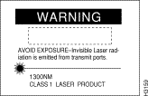
Warning 

Check all existing cables for conformance with CDDI/MLT-3 distance requirements and to ensure that you have the proper connectors (modular
RJ-45). Following are cable and distance specifications:
When you plan your CDDI installation, remember the following:
The IEEE 802.3 Ethernet 10BaseF ports accept ST-type connections using 62.5/125-micron multimode optical fiber. The distance limitation for 10BaseF is 1.2 miles (2 km). 10BaseF supports both the 10BaseFL (fiber link) and fiber-optic interrepeater link (FOIRL) standards.
In general, distance limitations depend on the combined effects of fiber, connectors, and the power levels of other devices on the fiber link. Table 2-2 lists the maximum power levels for 10BaseF and FOIRL.
| Maximum Power | 10BaseF | FOIRL |
|---|---|---|
| Transmit power at transmitter | -12 dB1 | -9 dB |
| Receive power at receiver | -32.5 dB | -27 dB |
The Ethernet 10BaseT ports accept modular RJ-45 connectors. For pinouts of the Ethernet 10BaseT ports, refer to the appendix "Wiring Specifications." 10BaseT requires a minimum of category 3 UTP cable as specified by the EIA/TIA-568-B wiring standard. The distance limitation for 10BaseT is a maximum of 328 feet (100 m) between segments.
As with all signaling systems, EIA/TIA-232 signals can travel a limited distance at any given bit rate. Generally, the slower the data rate, the greater the distance. Table 2-3 shows the relationship between baud rate and maximum distance. The EIA/TIA-232 admin. port requires a modular RJ-45 connector for the switch end, and an RJ-45-to-DB-25 adapter for the console terminal where it is attached.
| Data Rate (baud) | Distance (feet) | Distance (meters) |
|---|---|---|
| 2,400 | 200 | 60 |
| 4,800 | 100 | 30 |
| 9,600 | 50 | 15 |
| 19,200 | 25 | 7.6 |
| 38,400 | 12 | 3.7 |
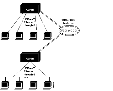
When the switch is installed in your network, the resulting topology might resemble the high-speed transparent and translational bridging overview shown in Figure 2-3. This consists of workstations connected to the 10BaseT Ethernet ports of two switches. The 10BaseF ports might be connected in a similar manner. The switches are connected to a CDDI or FDDI dual ring, which is part of a larger CDDI or FDDI backbone.

Operating the switch with a modem is optional. To connect the switch to a modem, you should consult the modem documentation. At a minimum, you need to connect the modem to the EIA/TIA-232 admin. port on the switch. You need to configure the modem to operate with the switch because no configuration is possible at the switch. As an example modem configuration, Table 2-4 lists the dual inline package (DIP) switch settings for the U.S. Robotics Sportster 14,400-baud fax modem.
| Switch | Setting | Function | Explanation |
|---|---|---|---|
| 1 | Down | DTR override | Modem ignores Data Terminal Ready (DTR). |
| 2 | Up | Audible results | Modem returns audible result messages instead of a number. |
| 3 | Up | Suppress results | Modem does not return any result messages. Required because this function is not configurable on the switch. |
| 4 | Down | No echo of offline commands | Modem does not echo when it is offline and it receives a command. Required because this function is not configurable on the switch. |
| 5 | Up | Auto answer on ring | Modem answers automatically after one ring. Required because this function is not configurable on the switch; therefore, the modem must answer automatically. |
| 6 | Down | CD override | Modem always asserts Carrier Detect (CD). |
| 7 | Down | Load factory defaults | This is modem-dependent. |
| 8 | Up | Dumb mode | Modem does not recognize modem attention (AT) command. |
Table 2-5 provides a list of tools and supplies you need to install the switch. The switch can be mounted in a standard 19-inch rack, on a wall in a wiring closet or office, or placed on a desktop in a work area.
| Type of Installation | |||
| Tools and Hardware | Rack | Wall | Desk |
| Rack-mount kit (standard):
Two brackets | Yes | No | No |
| Wall-mount kit1(optional):
Two brackets | No | Yes | No |
| No. 2 Phillips screwdriver | Yes | Yes | No |
| Flat-blade screwdriver (to remove A/B port cards or blank plates) | Yes | Yes | Yes |
| 3/8'' (0.952 cm) drill with 1/4'' (0.635 cm) bit | No | Yes | No |
|
|