|
|

This appendix lists the pinouts and wiring specifications for the EIA/TIA-232 admin. port, CDDI UTP, 10BaseT, SUM port, and the optical bypass switch.
Table A-1 and Table A-2 list the pinouts for the EIA/TIA-232 admin. port.
| At the Switch | At the Console (DTE) | ||||
|---|---|---|---|---|---|
| Signal | Definition | RJ-45 Pin | Direction | DB-25 Pin | Signal |
| CTS | Clear To Send | 1 <-- | Output | 4 | RTS |
| DSR | Data Set Ready | 2 <-- | Output | 20 | DTR |
| RXD | Receive Data | 3 <-- | Output | 2 | TX |
| GND | Ground | 4 | - | 7 | GND |
| GND | Ground | 5 | - | - | - |
| TXD | Transmit Data | 6 --> | Input | 3 | RXD |
| DTR | Data Terminal Ready | 7 --> | Input | 6 | DSR |
| RTS | Request To Send | 8 --> | Input | 5 | CTS |
| At the Switch | At the Modem (DCE) | ||||
|---|---|---|---|---|---|
| Signal | Definition | RJ-45 Pin | Direction | DB-25 Pin | Signal |
| CTS | Clear To Send | 1 <-- | Output | 5 | CTS |
| DSR | Data Set Ready | 2 <-- | Output | 8 | DCD |
| RXD | Receive Data | 3 <-- | Output | 3 | RX |
| GND | Ground | 4 | - | 7 | GND |
| GND | Ground | 5 | - | - | GND |
| TXD | Transmit Data | 6 --> | Input | 2 | TX |
| DTR | Data Terminal Ready | 7 --> | Input | 20 | DTR |
| RTS | Request To Send | 8 --> | Input | 4 | RTS |
Following are pinouts and cabling requirements for CDDI UTP wiring.
Table A-3 lists the pinout used for the CDDI/MLT-3 A/B port card transmit and receive pairs.
| Pin | Signal | Pin | Signal |
| 1 | TX+ | 5 | - |
| 2 | TX- | 6 | - |
| 3 | - | 7 | RX+ |
| 4 | - | 8 | RX- |
You must use modular, cross-connect cables in the following configurations:
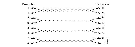
Each of the four pairs of wires that make up the twisted-pair cross-connect cable must be individually twisted. For example, the wire pair connecting pins 1 and 2 at one end of the cable must connect to pins 8 and 7 at the other end. (See Figure A-1.)

The cabling from A ports to B ports must be cross-connect, twisted-pair. Each of the four pairs of wires that make up the twisted-pair cable must be individually twisted. Table A-4 lists the EIA/TIA-568-B RJ-45 wiring scheme.
| Pin | Pair | Color |
|---|---|---|
| 1 | 2 | White/orange |
| 2 | 2 | Orange |
| 3 | 3 | White/green |
| 4 | 1 | Blue |
| 5 | 1 | White/blue |
| 6 | 3 | Green |
| 7 | 4 | White/brown |
| 8 | 4 | Brown |
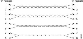
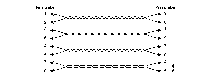
The 10BaseT cabling from the workstation to the switch must be straight-through, twisted-pair. Each of the four pairs of wires that make up the twisted-pair cable must be individually twisted. Figure A-2 shows straight-through cables and Figure A-3 shows cross-connect cables.


Table A-5 lists the pinout for Ethernet 10BaseT LAN port cabling.
| Pin | Signal | Pin | Signal |
|---|---|---|---|
| 1 | RX+ | 5 | - |
| 2 | RX- | 6 | TX- |
| 3 | TX+ | 7 | - |
| 4 | - | 8 | - |
Table A-6 lists the pinout for the optional Ethernet 10BaseT SUM port.
| Pin | Signal | Pin | Signal |
|---|---|---|---|
| 1 | TX+ | 5 | - |
| 2 | TX- | 6 | RX- |
| 3 | RX+ | 7 | - |
| 4 | - | 8 | - |
Table A-7 lists the pinout for the optical bypass connector, and Figure A-4 shows the connector. The connector is a female Deutsche Industrie Norm (DIN) type.
| Pin | Function |
|---|---|
| 1 | V+ |
| 2 | V+ |
| 3 | Switch |
| 4 | Switch |
| 5 | GND |
| 6 | Bypass present |

|
|