|
|

This chapter describes how to configure Multiprotocol over ATM (MPOA) on the ATM modules for the Catalyst 5000 and 6000 family switches.
 |
Note For information on installing the Catalyst 5000 family ATM modules, refer to the Catalyst 5000 Family Module Installation Guide. For information on installing Catalyst 6000 family ATM modules, refer to the Catalyst 6000 Family Module Installation Guide. |
|
Note For syntax and usage information for the commands used in this chapter, see "Command Reference." |
This chapter consists of these sections:
These sections describe how MPOA works:
MPOA enables the fast routing of internetwork-layer packets across a nonbroadcast, multiaccess (NBMA) network. MPOA replaces multihop routing with point-to-point routing using a direct virtual channel connection (VCC) between ingress and egress edge devices or hosts. An ingress edge device or host is the point at which an inbound flow enters the MPOA system; an egress edge device or host is the point at which an outbound flow exits the MPOA system.
These components are required for using MPOA across an NBMA network:
MPOA combines the benefits of LANE and NHRP to provide an efficient transfer of intersubnet unicast data in a LANE environment. The LANE protocol allows subnets to be bridged across the ATM/LAN boundary and provides interoperability between Ethernet and Token Ring architecture using ELANs. In this situation, LANE provides an effective means of bridging intrasubnet data across an ATM network. Intersubnet traffic between ELAN hosts, however, still needs to be routed. To minimize the hop count for intersubnet traffic over an ATM network, NHRP divides the ATM network into logical IP subnets. Although routers are still required to connect these subnets, NHRP allows intermediate routers to be bypassed by providing an extended address resolution protocol that permits Next Hop Clients (NHCs) to send queries directly between subnets. By integrating LANE and NHRP, MPOA extends the benefits of LANE by allowing intrasubnet communication over ATM VCCs without requiring routers in the data path.
Using NHRP's extended address resolution protocol, MPOA increases performance and reduces latencies by identifying the edge devices, establishing a direct VCC between the ingress and egress edge devices, and forwarding Layer-3 packets directly over this shortcut VCC, which bypasses the intermediate routers. An MPC provides the direct VCCs between the edge devices or hosts whenever possible and forwards Layer-3 packets over these shortcut VCCs. To establish shortcuts, MPCs communicate with MPSs resident on routers. The MPSs interact with their local Next Hop Servers (NHSs), which form part of the MPSs, to initiate and answer resolution requests. When an MPS receives updates from its NHS, it updates or purges relevant MPC caches as appropriate.
Figure 5-1 shows the MPOA message flow sequence between MPCs and MPSs (see Table 5-1 for definitions of the MPOA terms used in Figure 5-1).
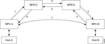
The MPOA message flow sequence occurs as follows:
1. MPOA resolution request sent from MPC-A to MPS-C
2. NHRP resolution request sent from MPS-C to MPS-D
3. MPOA cache-imposition request sent from MPS-D to MPC-B
4. MPOA cache-imposition reply sent from MPC-B to MPS-D
5. NHRP resolution reply sent from MPS-D to MPS-C
6. MPOA resolution reply sent from MPS-C to MPC-A
7. Shortcut VCC established
| MPOA Term | Definition |
MPOA resolution request | A request from an MPC to resolve a destination protocol address to an ATM address to establish a shortcut VCC to the egress device. |
NHRP resolution request | An MPOA resolution request that has been converted to an NHRP resolution request. |
MPOA cache-imposition request | A request from an egress MPS to an egress MPC providing the MAC rewrite information for a destination protocol address. |
MPOA cache-imposition reply | A reply from an egress MPC acknowledging an MPOA cache-imposition request. |
NHRP resolution reply | An NHRP resolution reply that will eventually be converted to an MPOA resolution reply. |
MPOA resolution reply | A reply from the ingress MPS resolving a protocol address to an ATM address. |
Shortcut VCC | The path between MPCs over which Layer-3 packets are sent. |
The MPC functionality involves ingress/egress cache management, data-plane and control-plane virtual circuit connection (VCC) management, MPOA frame processing, and MPOA protocol and MPOA
flow detection.
The MPC connects the Lan Emulation Clients (LECs) to higher internetworking layers. Each MPC can serve more than one LEC, but each LEC must be associated with only one MPC. Each MPC has its own MPC control ATM address, which may coincide with the ATM address of one of its member LECs. The MPC control ATM address is contained in MPOA Device Type TLV, and the MPC supplies each member LEC with this information. Each time a LEC sends out an LE_ARP response, it includes this MPC Device Type TLV, indicating the control ATM address of the MPC with which it is associated.
An MPC identifies packets sent to an MPOA-capable router over the NBMA network and, if possible, establishes a shortcut VCC to the egress MPC. The MPC routes these packets directly over this shortcut VCC, bypassing the intermediate routers and enabling the fast routing of internetwork-layer packets across an NBMA network. A Catalyst 5000 or 6000 family switch configured with an MPOA-capable ATM module can be designated as an MPC. The MPC is then configured directly on the ATM module.
The MPS supplies the forwarding information used by the MPCs. The MPS responds with the information after receiving a query from a client. To support the query and response functions, MPOA uses NHRP. The MPS on the router can also terminate shortcuts.
A Catalyst 5000 family switch configured with a Route Switch Module (RSM) and a Versatile Interface Processor 2 (VIP2) containing an ATM port adapter can function as an MPS. The MPS is configured on the RSM module, not the ATM module.
Typically, a router is designated as an MPS, but can also be designated as an MPC. Configuring an MPC on a router provides router-initiated and router-terminated shortcuts for non-NBMA networks. For this reason, in this publication MPC refers to a Catalyst 5000 or 6000 family switch, and MPS refers to a router or an RSM/VIP2 with an ATM port adapter in a Catalyst 5000 family switch.
The MPS software module implements the functionality of the MPS in compliance with the ATM Forum MPOA specification. These sections describe the functions of MPS:
MPS has to interact with the NHRP module in the router to smoothly propagate MPOA/NHRP packets end to end. MPOA frames are identical to NHRP frames except for some minor modifications and extensions for MPOA.
This process explains the interaction between an MPS and NHRP:
1. The MPS converts MPOA resolution requests to NHRP requests and sends it either to the next hop MPS or to the NHS depending on the configuration. The MPS searches for the next hop routing information to determine the interface and sends the packet with correct encapsulation to an MPS or an NHS.
2. The NHS sends resolution requests to the MPS when the next hop is on a LANE cloud or when the NHS is unsure of the packet destination. The MPS may do further processing, such as prompt the NHS to terminate the request or throw away the packet.
3. The NHS sends resolution replies to the MPS when the next hop interface is LANE or when the replies terminate in the router.
4. The MPS sends an MPOA resolution reply to the MPC.
Within a router, you can permit shortcuts between some groups of LECs and deny shortcuts between other groups. A network ID is associated with an MPS. By default, all the MPSs in a router get a network ID of 1.
If you want to segregate traffic, you can give MPSs different network IDs, preventing shortcuts between LECs served by different MPSs. You can configure MPS network IDs when you define an MPS database.
If a router has both MPS and NHRP configured, then the same network ID is required to facilitate requests, replies, and shortcuts across the MPS and NHRP. The interface-specific NHRP command
(ip nhrp network-id) must be the same for an MPS; otherwise, you will have a disjointed network.
Figure 5-1 shows how MPOA messages flow from Host A to Host B. In this figure, an MPC (MPC-A) residing on a host or edge device detects a packet flow to a destination IP address (Host B) and sends an MPOA resolution request. An MPS (MPS-C) residing on a router converts the MPOA resolution request to an NHRP resolution request and passes it to the neighboring MPS/NHS (MPS-D) on the routed path. When the NHRP resolution request reaches the egress point, the MPS (MPS-D) on that router sends an MPOA cache-imposition request to MPC-B. MPC-B acknowledges the request with a cache-imposition reply and adds a tag that allows the originator of the MPOA resolution request to receive the ATM address of MPC-B. As a result, the shortcut VCC between the edge MPCs (MPC-A and MPC-B) is set up.
When traffic flows from Host A to Host B, MPC-A is the ingress MPC and MPC-B is the egress MPC. The ingress MPC contains a cache entry for Host B with the ATM address of the egress MPC. The ingress MPC switches packets destined to Host B on the shortcut VCC with the appropriate tag received in the MPOA resolution reply. Packets traversing through the shortcut VCC do not have any DLL headers. The egress MPC contains a cache entry that associates the IP address of Host B and the ATM address of the ingress MPC to a DLL header. When the egress MPC switches an IP packet through a shortcut path to Host B, it appears to have come from the egress router.
An MPOA network must have at least one MPS, one or more MPCs, and optional intermediate routers implementing NHRP servers. The MPSs and MPCs use LANE control frames to discover one another in the LANE network.
 |
Caution For MPOA to work properly, you must first create an emulated LAN (ELAN) identifier for each ELAN. Use the lane config database or the lane server-bus ATM LANE commands to create ELAN identifiers. These commands are described in "Command Reference." |
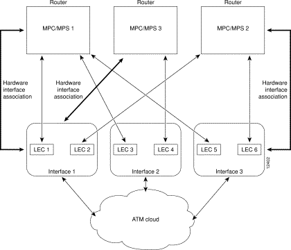
An MPC and MPS can serve one or more LECs. The LEC can be associated with any MPC and MPS in the router or with an MPC in a Catalyst 5000 or 6000 family ATM module. A LEC can be attached to only one MPC or one MPS at a time.
Figure 5-2 shows the relationships between MPC/MPS and LECs.
These guidelines apply when configuring MPOA on the Catalyst 5000 and 6000 family switches:
|
Note An MPC or MPS can be attached to a single hardware interface only. |
|
Note After a LEC is bound to an MPC or MPS, you must unbind the LEC from the first MPC or MPS before binding it to another MPC or MPS. Typically, you do not need to configure more than one MPS in a router. |
|
Note If any LEC resides on a different (unreachable) ATM network from the one to which the hardware interface is connected, MPOA does not operate properly. |
This section contains the following information about how you can configure, monitor, and maintain the MPC:
To obtain the MPC operational parameters, use one of the following methods:
For additional configuration information, refer to the Release Notes for RSM, Cisco 4500, 4700, 7200, and 7500 Routers for Cisco IOS Release 11.3(3a)WA4(5) publication.
For MPOA to work properly, LECs and MPCs must have the same ELAN IDs. When a LEC wants to communicate across the ATM cloud using MPOA, it must belong to an ELAN that has a defined ELAN ID. The MPC representing this LEC must also have the same ELAN ID. Typically, the ELAN ID is obtained by the LEC from the LECS database during registration. However, because it is possible to manually provide a LEC with the LES ATM address, the LEC may not receive the ELAN ID. In that case, you must provide the LEC with the ELAN ID manually.
|
Note If the LEC and the MPC representing the LEC do not share the same ELAN ID, the LEC is not reachable through the MPOA system. |
To manually define an ELAN ID, perform this task:
| Task | Command | |
|---|---|---|
Step 1 | Define an ELAN ID for the LEC (in LANE database configuration mode). | name elan-name elan-id id |
Step 2 | Configure the LEC with the ELAN ID (in interface configuration mode). | lane server-bus ethernet elan-name [elan-id id] |
|
Caution If an ELAN ID is supplied, make sure both commands use the same elan-id value. |
To configure an MPC on a Catalyst 5000 or 6000 family ATM module, you must establish connection with the ATM module, enter privileged mode, and then enter configuration mode. For information on performing these tasks, see the "ATM Module CLI Overview" section.
To configure an MPC on your network, perform this task in the appropriate configuration modes:
| Task | Command | |
|---|---|---|
Step 1 | In global configuration mode, define an MPC with a specified name. | mpoa client config name mpc-name |
Step 2 | In interface configuration mode, specify the physical ATM interface which the MPC is to be associated with. | interface atm0 {mod_num/port_num} |
Step 3 | In interface configuration mode, attach an MPC to the ATM interface. | mpoa client name mpc-name |
Step 4 | In interface configuration mode, specify the ATM interface that contains the LEC to which you will bind the MPC. | interface atm_num.sub_interface_num mul |
Step 5 | In interface configuration mode, bind a LANE client to the specified MPC. | lane client mpoa client name mpc-name |
Step 6 | Repeat Steps 4 and 5 for every LEC to be served by the MPC/MPS. |
|
|
Note In Step 2, you must specify the physical interface, atm0, for the MPC. |
|
Note In Step 4, you must specify the mul keyword when entering a subinterface number. Otherwise, the CLI does not accept the command. |
This example configures an MPC named MPC1 and attaches it to a LEC configured on interface atm0.2. The show mpoa client command verifies the configuration.
ATM#configure terminal

Enter configuration commands, one per line.  End with CNTL/Z.
ATM(config)#mpoa client config name MPC1

ATM(config)#interface atm0

ATM(config-if)#mpoa client name MPC1

ATM(config-if)#interface atm0.2 mul

ATM(config-subif)#lane client mpoa client name MPC1

ATM(config-subif)#^Z

ATM#show mpoa client


MPC Name: MPC1, Interface: ATM0, State: Up
MPC actual operating address: 47.00918100000000E04FACB401.00E04FACB095.00
Shortcut-Setup Count: 10, Shortcut-Setup Time: 1
Lane clients bound to MPC MPC1: ATM0.2
ATM#
To monitor and maintain the configuration of an MPC, perform any of these tasks in EXEC mode:
Task
| Command
|
|---|---|
| |
| |
| |
| |
| |
|
Note Currently, the Catalyst 6000 family switches do not support the MPS function. |
If you are using a Catalyst 5000 family switch with a Route Switch Module (RSM) and a VIP2 containing an ATM port adapter, you can configure the MPS to run on the switch. To configure the MPS, you will need to session into the RSM and perform all configurations from that module.
To configure an MPS on your network, perform the tasks in the following sections. Only the first task is required; the remaining two tasks are optional.
|
Caution For LECs to reach each other through an MPC and an MPS, all components must have the same ELAN ID. If you configure the ELAN IDs manually, make sure they are identical. See the "Configuring the ELAN ID" section for information on how to configure the ELAN ID. |
To configure an MPS, session in to the RSM and perform these tasks:
| Task | Command | |
|---|---|---|
Step 1 | In global configuration mode, define an MPS with the specified name. | mpoa server config name mps-name |
Step 2 | Specify the ATM interface to attach the MPS. | interface atm {slot/port | number} |
Step 3 | In interface configuration mode, attach the MPS to the ATM interface. | mpoa server name mps-name |
Step 4 | Specify the ATM interface to bind the MPS to a LEC. | interface atm {slot/port.subinterface-number | number.subinterface-number} |
Step 5 | In subinterface configuration mode, bind a LANE client to the specified MPS. | lane client mpoa server name mps-name |
This example configures an MPS named MPS-1 and binds it to a LEC configured on interface atm3/0:
RSM-ER-F1#configure terminal

Enter configuration commands, one per line.  End with CNTL/Z.
RSM-ER-F1#(config)#mpoa server config name MPS-1

RSM-ER-F1#(mpoa-server-config)#interface atm3/0

RSM-ER-F1#(config-if)#mpoa server name MPS-1

RSM-ER-F1#(config-if)#interface atm3/0

RSM-ER-F1#(config-if)#lane client mpoa server name MPS-1
You must define an MPS with a specified name before you can change the MPS variables that are specific to that MPS.
To change MPS variables specific only to a particular MPS, perform this task starting in MPS configuration mode:
| Task | Command | |
|---|---|---|
Step 1 | Define an MPS with the specified name. | mpoa server config name mps-name |
Step 2 | (Optional) Specify the control ATM address that the MPS should use (when it is associated with a hardware interface). | atm-address atm-address |
Step 3 | (Optional) Specify the network ID of the MPS. | network-id id |
Step 4 | (Optional) Specify the keepalive time value variable of the MPS. | keepalive-time time |
Step 5 | (Optional) Specify the holding time value variable of the MPS. | holding-time time |
This example configures MPS variables and verifies the configuration:
RSM-ER-F1#(config)#mpoa server config name MPS-1

RSM-ER-F1#(mpoa-server-config)#atm-address 47.00318100000000100826E901.0020D1AA1P58.01

RSM-ER-F1#(mpoa-server-config)#network-id 3

RSM-ER-F1#(mpoa-server-config)#keepalive-time  10

RSM-ER-F1#(mpoa-server-config)#holding-time 600

RSM-ER-F1#(config)#^Z
RSM-ER-F1#show mpoa server name MPS-1


MPS Name: MPS-1, MPS id: 1, Interface: ATM3/0, State: up
network-id: 3, Keepalive: 10 secs, Holding time: 600 secs
Keepalive lifetime: 35 secs, Giveup time: 40 secs
MPS actual operating address: 47.00318100000000100826E901.0020D1AA1P58.01
Lane clients bound to MPS MPS-1: ATM3/0 ATM3/0.101 ATM3/0.102
Discovered neighbours:
MPS 47.00917100000000200126PC01.00E0FEA3B451.00 vcds: 81(L,A)
MPC 47.00917100000000200726E901.00800726E592.00 vcds: 12(L,A)
MPC 47.00917100000000200726BC01.00700726B855.00 vcds: 91(L,A)
RSM-ER-F1#
To monitor and maintain the configuration of an MPS, perform one of these tasks in EXEC mode:
Task
| Command
|
|---|---|
| |
| |
| |
| |
| |
| |
![]()
![]()
![]()
![]()
![]()
![]()
![]()
![]()
Posted: Tue Nov 28 00:22:48 PST 2000
Copyright 1989-2000©Cisco Systems Inc.