|
|

This chapter describes how to prepare your site before installing switching modules in Catalyst 5000 family switches and consists of these sections:
 | Warning Before you install, operate, or service the system, read the Site Preparation and Safety Guide. This guide contains important safety information you should know before working with the system. |
This section discusses several topics you should consider before installing switching modules in Catalyst 5000 family switches.
The length of your networks and the distances between connections depend on the signal type, the signal speed, and the transmission media (the type of cabling used to transmit the signals). For example, fiber-optic cable has a greater channel capacity than twisted-pair cabling. The distance and rate limits in this chapter are the IEEE-recommended maximum speeds and distances for signaling. However, if you understand the electrical problems that might arise and can compensate for them, you should get good results with rates and distances greater than those described here, although you do so at your own risk.
When preparing your site for network connections to the switching modules, you need to consider factors for each interface type:
Before installing the switching modules, have all additional external equipment and cables on hand. If you intend to build your own cables, see Appendix A, "Specifications."
You might need some of the following data communications equipment to complete your installation:
This section describes the types of cables and connectors you will need to install the switching modules.
Ethernet and Fast Ethernet modules use six different types of connectors:


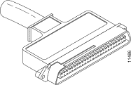


The 24-port, switched 10BaseT module can use both 90-degree and 180-degree male telco connectors, as shown in Figure 2-2 and Figure 2-3. The 48-port 10BaseT modules require 180-degree male telco connectors.
Ethernet transceivers for Virtual Terminal Protocol (VTP) and multimode fiber-optic cabling (100BaseFX at 100 Mbps) are available from a variety of suppliers.
Figure 2-8 shows examples of Fast Ethernet transceivers and connection equipment.
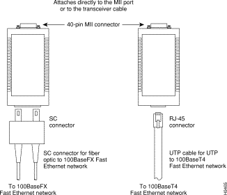
When planning your connections, consider the types and locations of connectors on adjacent switching modules so that the transceiver does not overlap and impair access to other connections.
Table 2-1 lists the IEEE maximum transmission distances for Ethernet and Fast Ethernet.
| Transceiver Speed | Cable Type | Duplex Mode | Maximum Distance between Stations |
|---|---|---|---|
10 Mbps | Full and half | 328 ft (100 m) | |
10 Mbps | Multimode fiber | Full and half | 1.2 miles (2 km) |
100 Mbps | Full and half | 328 ft (100 m) | |
100 Mbps | Full | 1.2 miles (2 km) | |
100 Mbps | Multimode fiber | Half | 1352 ft (412 m) |
100 Mbps | Single-mode fiber | Half | 1352 ft (412 m) |
100 Mbps | Single-mode fiber | Full | 6.2 miles (10 km) |
Both the Gigabit Ethernet module (WS-X5403) and the Gigabit EtherChannel module (WS-X5410) use Gigabit Interface Converters (GBICs). The GBIC is a hot-swappable input/output device that plugs into a Gigabit Ethernet or EtherChannel module, linking the module with the fiber-optic network. All GBIC ports have SC-type connectors. A GBIC is shown in Figure 2-9.

Table 2-2 lists the three styles of GBICs that are currently available.
| GBIC | Product Number |
|---|---|
1000BaseSX | WS-G5484 |
1000BaseLX/LH | WS-G5486 |
1000BaseZX | WS-G5487 |
Table 2-3 provides cabling specifications for the GBICs that you install in the Gigabit Ethernet or Gigabit EtherChannel module.
| GBIC | Wavelength (nm)1 | Fiber Type | Core Size (micron) | Modal Bandwidth (MHz/km) | Cable Distance |
|---|---|---|---|---|---|
SX2 | 850 | MMF | 62.5 | 160 | 722 ft (220 m) |
|
|
| 62.5 | 200 | 902 ft (275 m) |
|
|
| 50.0 | 400 | 1640 ft (500 m) |
|
|
| 50.0 | 500 | 1804 ft (550 m) |
LX/LH | 1300 | MMF | 62.5 | 500 | 1804 ft (550 m) |
|
|
| 50.0 | 400 | 1804 ft (550 m) |
|
|
| 50.0 | 500 | 1804 ft (550 m) |
|
| SMF | 9/10 | - | 6.2 miles (10 km) |
ZX3 | 1550 | SMF | 9/10 | - | 43.5 miles (70 km) |
|
| SMF4 | 8 | - | 62.1 miles (100 km) |
| 1Nominal fiber specification wavelength. 2MMF only. 3A maximum of 6 ZX GBICs are supported in a switch chassis. 4Dispersion-shifted single-mode fiber-optic. |
Table 2-4 provides the GBIC optical power characteristics.
| Parameter | 1000BaseSX (WS-G5484) | 1000BaseLX/LH (WS-G5486) | 1000BaseZX (WS-G5487) |
|---|---|---|---|
Transmitter output power (min/max) | -9.5/0 dBm | -9.5/-3 dBm | 0/4.77 dBm |
Receiver maximum input power | 0 dBm | -3 dBm | -3 dBm |
Receiver sensitivity | -17 dBm | -19 dBm | -23 dBm |
Channel insertion loss |
|
|
|
| 3.4 dBm | 4.4 dBm | n/a |
| 3.2 dBm | 6 dBm | n/a |
| n/a | 6.5 dBm | 21.5 dBm |
| 11 micron (µ) equals 1 micrometer or 10-6 meters |
You must observe the following optical-fiber cabling restrictions when using GBICs:
CDDI is the implementation of FDDI protocols over foil twisted-pair (FTP) and UTP cabling. CDDI transceivers transmit over short distances (about 100 feet), providing data rates of 100 Mbps using a dual-ring architecture to provide redundancy.
FDDI and CDDI standards set the maximum allowable distances between stations and the maximum allowable cable lengths. Table 2-5 lists the maximum transmission distances for each transceiver type.
| Transceiver Type | Maximum Distance between Stations |
|---|---|
Single-mode | 18.6 miles (30 km) |
Multimode | 1.2 miles (2 km) |
Category 5 UTP | 328 ft (100 m) |
Table 2-6 lists the typical fiber-optic link attenuation and dispersion limits.
| Single-Mode | Multimode | |
|---|---|---|
Attenuation | 0.4 dB | 2.4 to 3.0 dB/km |
Dispersion limit | No limit | 500 MHz/km1 |
| 1The product of bandwidth and distance must be less than 500 MHz/km. |
The standards allow a maximum of 500 stations in an FDDI/CDDI network. Both single-mode and multimode transceiver types provide 11 dB of optical power.
Fiber-optic transceivers on the FDDI/CDDI modules provide a direct interface between the switch and the FDDI/CDDI ring. The FDDI modules support multimode transceivers. Multimode transceivers provide a Class A dual-attachment interface that can connect to a Class A or a Class B station. Class A is a dual-attachment station (DAS) with primary and secondary rings; Class B is a single-attachment station (SAS) with only a primary ring. See the "Setting Up the FDDI/CDDI Network" section, for a detailed description of Class A and Class B stations and of DASs and SASs.
FDDI networks use two types of fiber-optic cable: single-mode fiber (SMF) and multimode fiber (MMF). The term mode refers to the angle that light rays (signals) reflect and propagate through the optical-fiber core, which acts as a waveguide for the light signals. MMF has a thick core (62.5 micron) that reflects light rays at many angles. SMF has a thin core (8.7 to 10 micron) that allows light to enter only at a single angle.
Although MMF allows more light signals to enter at a greater variety of angles (modes), the different angles create multiple propagation paths that cause the signals to spread out in time and limit the rate at which data can be accurately received. This distortion does not occur on the single path of the single-mode signal; therefore, SMF is capable of higher bandwidth and greater cable run distances than MMF. Typically, multimode transmitters use LEDs as a light source. Single-mode transmitters use a laser diode, which can sustain faster data rates. Single-mode and multimode interfaces use a photodiode detector at the receiver to translate the light signal into electrical signals. Table 2-7 lists the FDDI transmitter power and receiver sensitivities for MMF and SMF.
| Characteristic | Specification |
|---|---|
FDDI MMF |
|
Optical source | LED |
Transmitter output power | -18.5 to -14 dBm |
Receiver sensitivity | -34 to -14 dBm |
Maximum cabling distance | 1.2 miles (2 km) |
FDDI SMF |
|
Optical source | laser |
Transmitter output power | -7 to -4 dBm |
Receiver sensitivity | -33 to -14 dBm |
Maximum cabling distance | 18.6 miles (30 km) |
Table 2-8 shows the transmit power levels for FDDI media.
| Fiber Type | Average Optical Power | |
|---|---|---|
| Maximum | Minimum | |
Single-mode | -4 dBm | -7 dBm |
Multimode | -14 dBm | -18.5 dBm |
Table 2-9 shows the receive power levels for FDDI media.
| Fiber Type | Average Optical Sensitivity | Average Maximum Input Power |
|---|---|---|
Single-mode | -33 dBm | -14 dBm |
Multimode | -34 dBm | -14 dBm |
The CDDI transceiver supports distances of up to 328 feet (100 meters). The CDDI connector is a CDDI-standard physical sublayer (PHY) connector that encodes and decodes the data into a format acceptable for UTP transmission. The CDDI connector accepts RJ-45 connectors, shown in Figure 2-10, with standard UTP cables.

Before you install CDDI modules, confirm that all existing cables conform with CDDI distance requirements and ensure that you have the proper modular RJ-45 connectors. CDDI cable and distance specifications are as follows:
When you plan your CDDI installation, remember the following:
The multimode transceiver supports distances of up to 1.2 miles (2 kilometers). The multimode connector is an FDDI-standard PHY connector that encodes and decodes the data into an acceptable format for fiber transmission. The multimode connector accepts standard 62.5/125-micron, multimode fiber-optic cable and with proper cable terminators, the connector can accept 50/125-micron fiber-optic cable. Multimode fiber-optic cable uses the integrated media interface connector (MIC), shown in Figure 2-11, at the FDDI module and the network ends.

The single-mode transceivers support distances up to 18.6 miles (30 km). The single-mode connector, shown in Figure 2-12, accepts standard 8.7- or 10/125-micron, single-mode fiber-optic cable using ST-type connectors for transmit and receive ports.

The FDDI modules provide a control port for an optical bypass switch. The control port allows the light signal to pass directly through the bypass switch and completely bypass the FDDI module transceivers when the interface fails or is shut down. Most optical bypass switches provide the necessary interface cables for connection to the MIC connectors on the FDDI module. However, not all manufacturers use the same type of DIN connector for the control port; some manufacturers use a DIN, and some use a smaller version, a mini-DIN.
FDDI/CDDI, which specifies a 100-Mbps, token-passing, dual-ring network using UTP or fiber-optic transmission media, is defined by the American National Standards Institute (ANSI) X3.1 standard and by ISO 9314, the international version of the ANSI standard.
An FDDI/CDDI network consists of two token-passing rings: a primary ring and a secondary ring. An FDDI/CDDI ring consists of two or more point-to-point connections between adjacent stations.
On most FDDI/CDDI networks, the primary ring is for data communication and the secondary ring is a backup. Class B stations, or SASs, attach to one ring and attach through a concentrator, which provides connections for multiple SASs. Class A stations, or DASs, attach to both rings.
Figure 2-13 shows a typical FDDI/CDDI configuration with a DAS, SAS, and concentrator.
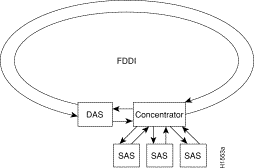
The concentrator in a typical FDDI/CDDI configuration ensures that a failure or power-down of any SAS does not interrupt the ring. SASs (Class B) use one transmit port and one receive port to attach to the single ring. DASs (Class A) use two physical ports, designated PHY A and PHY B, each of which connects the station to both the primary and secondary rings. Each port is a receiver for one ring and a transmitter for the other. For example, PHY A receives traffic from the primary ring, and PHY B transmits to the primary ring.
The dual rings in an FDDI/CDDI network provide fault tolerance. If a station on a dual ring shuts down or fails, such as Station 3 in Figure 2-14, the ring wraps automatically (doubles back on itself) to form a single contiguous ring. This action removes the failed station from the ring, but allows the other stations to continue operation. In Figure 2-14, the ring wraps to eliminate Station 3 and forms a smaller ring that includes only Stations 1, 2, and 4.
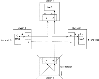
A second failure could cause the ring to wrap in both directions from the point of failure, which would segment the ring into two separate rings that could not communicate with each other. For example, if Station 1 in Figure 2-14 fails after Station 3 fails, Stations 2 and 4 are isolated because no path for communication exists between them. Subsequent failures cause additional segmentation.
Each station in a ring refers to its neighbor stations as upstream or downstream neighbors. The stream is based on the signal flow on the primary ring. A station receives the primary signal from its upstream neighbor and transmits the primary signal to its downstream neighbor.
For example, Figure 2-14 shows the primary signal flow transmitted from PHY B on Station 2 to PHY A on Station 1 and from PHY B on Station 1 to PHY A on Station 4. Using Station 1 as a reference, Station 2 is the upstream neighbor of Station 1, and Station 4 is the downstream neighbor of Station 1.
This section discusses topics that you should consider before connecting ATM LAN Emulation (LANE) modules to an ATM network.
When you use UTP Category 5 cabling for ATM LANE modules, note that the maximum transmission distance is 328 feet (100 meters). The maximum distances for ATM LANE fiber-optic network connections are determined by the transmitter output power, receiver sensitivity, and type of optical source. Table 2-10 lists the characteristics, including the maximum transmission distances, for both multimode and single-mode fiber-optic cables.
| Characteristic | Specification |
|---|---|
OC-3 MMF |
|
Optical source | LED |
Transmitter output power | -19 to -14 dBm |
Receiver sensitivity | -32.5 to -14 dBm |
Wavelength | 1270 to 1380 nm |
Maximum cabling distance | 6562 ft (2 km) |
OC-3 SMF |
|
Optical source | laser |
Transmitter output power | -14 to -8 dBm |
Receiver sensitivity | -32.5 to -8 dBm |
Wavelength | 1261 to 1360 nm |
Maximum cabling distance | 6.2 miles (10 km) |
OC-12 MMF |
|
Optical source | LED |
Wavelength | 1300 nm |
Transmitter output power | -19 to -14 dBm |
Receiver sensitivity | -26 to -14 dBm |
Maximum cabling distance | 1640 ft (500 m) |
OC-12 SMF |
|
Optical source | laser |
Wavelength | 1300 nm |
Transmitter output power | -15 to -8 dBm |
Receiver sensitivity | -28 to -8 dBm |
Maximum cabling distance | 9.3 miles (15 km) |
All ATM interfaces are full-duplex interfaces. You must use the appropriate ATM interface cable to connect the ATM multimode or UTP switching module with an external ATM network.
The ATM LANE switching modules provide an interface to ATM switching fabrics for transmitting and receiving data at rates of up to 155 Mbps (OC-3) bidirectionally; the actual rate is determined by the physical layer interface module (PLIM). The OC-12 dual PHY switching modules provide an interface to ATM switching fabrics for transmitting and receiving data at rates up to 622 Mbps (OC-12) bidirectionally.
The ATM LANE switching module can support PLIMs that connect to the following physical layers:
The ATM interface cable connects the switch to an ATM network or to two switches in series. You can obtain cables from these cable vendors:
For wide-area networking, ATM is currently being standardized in Broadband Integrated Services Digital Networks (BISDNs) by the International Telecommunication Union Telecommunication Standardization Sector (ITU-T) and ANSI. BISDN supports rates from E3 (34 Mbps) to multiple gigabits per second (Gbps).
The ATM User-Network Interface (UNI) specification defines the required Management Information Base (MIB) functionality for ATM interfaces. MIB attributes are readable and writable across the Integrated Local Management Interface (ILMI) using the Simple Network Management Protocol (SNMP). The ILMI uses SNMP together with the ATM ILMI MIB without User Datagram Protocol (UDP) or IP addressing to provide diagnostics, monitoring, and configuration services at the UNI.
The ATM LANE switching module supports RFC 1213 interface MIBs as specified in the ATM MIB V2 specification.
The ATM dual PHY DS3 module provides an interface to ATM switching fabrics for transmitting and receiving data at up to 45 Mbps bidirectionally.
This module uses 75-ohm RG-59 coaxial cable with bayonet-style twist-lock (BNC) connectors. Figure 2-15 shows the coaxial cable and BNC connectors.

The maximum station-to-station cabling distance for DS3 coaxial cable is 450 feet (137 meters).
When preparing your site for Token Ring connections, consider these factors:
The recommended distances for the various cable types are set by North American and international commercial building wiring standards. These standards state that standards-compliant horizontal copper cabling shall not exceed 295 feet (90 meters), leaving 33 feet (10 meters) total for required patch cabling in both the office and telecommunications closet.
The Token Ring network dedicated-media connections support only one attached system per connection.
In a Token Ring network, a lobe is a section of cable that attaches a device to an access unit.
For all supported cable types except optical fiber, IEEE recommends a maximum cable lobe length of 625 feet (190 meters) plus a 33-feet (10 meter) total allowance for the patch cords in the office and the telecommunications closets. For optical fiber, IEEE recommends a maximum cable lobe length of 6562 feet (2000 meters).
Table 2-11 and Table 2-12 specify the maximum supported lobe lengths for the following cable types. Allow an additional 33 feet (10 meters) per lobe length to accommodate patch cables, unless otherwise specified.
.
| Ring Speed | Types 1 and 1a, Types 2 and 2a | Type 8 | Type 9 |
|---|---|---|---|
4 Mbps | 2460 ft (750 m) | 1234 ft (376 m) | 1640 ft (500 m) |
16 Mbps | 952 ft (290 m) | 480 ft (146 m) | 656 ft (200 m) |
| Ring Speed | 100-ohm Type 3 Cable | 100-ohm Category 3 Cable | 100- or 120-ohm Category 4 Cable | 100- or 120-ohm Category 5 Cable |
|---|---|---|---|---|
4 Mbps | 328 ft (100 m) | 820 ft (250 m) | 1148 ft (350 m) | 1148 ft (350 m) |
16 Mbps | Not Supported | 328 ft (100 m) | 656 ft (200 m) | 656 ft (200 m) |
The cable types that you can use for shared-media LAN segments are the same as those described for dedicated-media segments. The hub or concentrator attached to the Catalyst 5000 family Token Ring module port determines the acceptable cable distances.
A Token Ring network can support up to 260 attached devices or nodes on a single network when you use 150-ohm shielded media (type 1, 1A, 2, or 2A). When you use cable segments with 100- or 120-ohm shielded media, this number decreases to 132 (72 if you use any 4-Mbps-only adapters or filters).
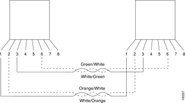
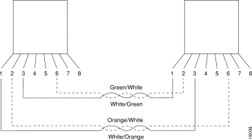
You must use a straight-through 100-ohm or 120-ohm cable when connecting devices to the Token Ring ports on the Catalyst 5000 family Token Ring module.
The RJ-45 connector on the Catalyst 5000 family Token Ring module makes ground available on the shield and on pins 1, 2, 7, and 8. Shielded cables provide continuity for the ground-to-any shielded connector on the other end of the cable.
Figure 2-16 and Figure 2-17 illustrate the straight-through 100-ohm and 120-ohm cable and the 150-ohm data connector-to-RJ-45 straight-through cable.
To connect to a Token Ring network, use RJ-45 male connectors, as shown in Figure 2-18.

The fiber Token Ring module provides 16 Volition VF-45 socket connections. Each Volition VF-45 connector supports an MMF connection to the Token Ring through a VF-45 to ST connector patch cable or VF-45 to SC connector patch cable. Figure 2-19 shows the Volition VF-45 connector.

For specific information on the RSM/VIP2 interface and cable requirements, refer to the Route Switch Module Catalyst VIP2-15 and VIP2-40 Installation and Configuration Note.
![]()
![]()
![]()
![]()
![]()
![]()
![]()
![]()
Posted: Wed Nov 22 08:50:35 PST 2000
Copyright 1989-2000©Cisco Systems Inc.