|
|

Product Number: WS-C5068B
 | Caution To avoid problems with the switch, do not mix DC input power supplies with AC input power supplies in individual switches. |
This document describes how to install the -48V DC power supply into the Catalyst 5000 series switch. This document contains the following sections:
For detailed information on installing, configuring, and maintaining the Catalyst 5000 series switch, see the Catalyst 5000 Installation Guide, the Catalyst 5000 Series Advanced Configuration Guide, and the Catalyst 5000 Series Command Reference publication.
Cisco documentation and additional literature are available in a CD-ROM package, which ships with your product. The Documentation CD-ROM, a member of the Cisco Connection Family, is updated monthly. Therefore, it might be more current than printed documentation.
Table 1 lists the -48V DC power supply specifications.
| Description | Specification |
|---|---|
Dimensions (H x W x D) | 2.7 x 6.0 x 15.3 in. (6.9 x 15.2 x 38.9 cm) |
Weight | 10 lb (4.54 kg) |
Environmental Conditions: | |
DC voltages supplied and steady-state maximum current ratings | +5V @ 70A |
Input voltage | -40.5VDC to 72VDC continuous |
Input current | 14.0A maximum @ 48 VDC (nominal) |
Output power | 376W |
600 W (2040 Btu1/hr) | |
Wire gauge for power cable | |
95 cfm4 through the system fan assembly | |
Agency approvals: | |
The -48 VDC power supply is required by many telcos because their wiring closets are equipped with DC power outlets. From an operational perspective, the DC power supply has the same characteristics as the AC version.
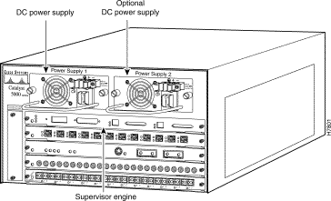
Figure 1 shows the location of the DC power supplies in a redundant configuration. In a nonredundant configuration the power supply goes in the slot labelled Power Supply 1.

In a redundant configuration, the power supplies provide system power simultaneously (load sharing). You can remove and replace one supply while the remaining supply immediately ramps up to full power to maintain uninterrupted system operation. Whenever possible, connect each power supply to a separate DC source.
In nonredundant or redundant configurations, the power supplies are hot-swappable; they can be replaced without powering down the system. The second, redundant power supply can be installed or replaced without interrupting system operation.
The supervisor engine module and the power supply front panels provide system power status as described in the following subsections.
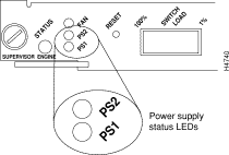
On the supervisor engine module front panel, the PS1 LED goes on when the power supply in the left bay, labeled Power Supply 1, is installed and supplying power to the system. The PS2 LED goes on when the power supply in the right bay, labeled Power Supply 2, is installed and supplying power to the system. Both the LEDs should be on in systems with redundant power. The supervisor engine module LEDs are shown in Figure 2 and described in Table 2.

| LED | Description |
|---|---|
If the left bay power supply is operational, the PS1 LED is green. | |
PS2 | If the right bay power supply is operational, the PS2 LED is green. |
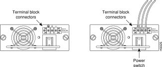
The green LED (see Figure 3) indicates the status of the power supply and internal DC voltages. The LED stays on when the power supply is on and receiving DC source power, providing +5, +12, and +24 VDC to internal components, and ensuring all internal voltages are within tolerance.
If the DC source power or any of the internal DC voltages exceed allowable tolerances, the LED goes off and the system environmental monitor messages indicate the out-of-tolerance line. Because the system requires all three output voltages for operation, the system will probably malfunction or shut down if any of the internal DC voltages reach an out-of-tolerance state.

The power supply monitors its own temperature and internal voltages. If the supply detects an overvoltage or overtemperature condition, it shuts down to avoid damage to the power supply or other system components.
The environmental monitoring functions use three levels of status conditions to monitor the system. These levels are normal, alarm, and power supply shutdown. The processor monitors the temperature inside the switching module compartment, and the power supplies use the normal and critical levels to monitor DC voltages. Table 3 lists temperature thresholds for the (processor-monitored) levels.
The power supply monitors its output voltages for out-of-tolerance conditions and displays proper operation by turning on its green LED.
| Parameter | Normal | Alarm |
|---|---|---|
Airflow | 10 to 55ºC | > 55ºC |
The three levels of status condition are as follows:
The processor uses the two levels of status conditions (normal, alarm) to monitor the air temperature in the switching-module compartment. Sensors on the supervisor engine module monitor the temperature of the cooling air that flows through the switching-module compartment. If the air temperature exceeds a defined threshold, the system processor displays warning messages on the console terminal. The processor stores the present parameter measurements for both temperature and DC voltage in NVRAM. These measurements can be retrieved by accessing a report that lists the last shutdown parameters.
If the processor detects that DC input power is dropping but can recover before the power supply shuts down, it logs the event as an intermittent power failure. The reporting functions display the cumulative number of intermittent power failures logged since the last power up.
The power supply has a built-in fan; air enters the front of the fan (DC input end) and exits through the back.
 | Warning Before performing the procedure, ensure that all power is off to the DC circuit. Locate the circuit breaker on the panel board that services the DC circuit and switch it to the OFF position. Tape the circuit breaker switch handle in the OFF position to prevent accidental closing of the circuit. |
Follow these steps to connect the -48 VDC power supply to the DC voltage source:
Step 1 Verify that power is OFF to the DC input circuit.
Step 2 Ensure that the power switch is in the OFF (0) position on the power supply.
Step 3 Remove the terminal block cover by depressing the two plastic levers on each side of the terminal block.
Step 4 Attach the appropriate lugs to the DC input wires. (Maximum width of lugs is 0.300 inch. Suggested lugs are AMP 322985 or 52941.)
Step 5 From the top of the terminal block, wire the DC input power supply to the terminal block as follows (see Figure 4):
Step 6 After ensuring that all wire connections are secure, reinstall the terminal block cover.
Step 7 If there is a redundant power supply installed, use Step 1 through Step 6 to connect it to a different DC input line than the initial power supply.
Step 8 The Catalyst 5000 series switch must be connected to the central office (CO) ground through the CO ground connector shown in Figure 5. Use the following guidelines when connecting the switch to the CO ground:
Step 9 Remove the tape from the circuit breaker switch handle and restore power by moving the circuit breaker switch handle to the on position.
Step 10 Turn the power switch to the on (-) position on the power supply.


Step 11 Verify that the green LED on the power supply front panel is on. This indicates that the power supply is on and receiving DC source power, providing +5, +12, and +24 VDC to internal components, and ensuring that all internal voltages are within tolerance.
Verify that the appropriate supervisor engine module PS1 and PS2 LEDs are on and green.
Step 12 Use the show system command to display the power supply and system status (see the "Using the show system Command" section for a screen example).
If the LEDs or show system command indicate a power or other system problem, refer to the Catalyst 5000 Installation Guide for troubleshooting information.
This section provides a removal and replacement procedure for power supplies. The Catalyst 5000 series switch is configured to your order and is ready for installation and startup when it leaves the factory. As your communication requirements change, you might want to upgrade your system and add or replace a power supply.
The -48 VDC power supplies (DC input) used in the switch support redundant hot-swapping. When two power supplies are installed, you can install, remove, or replace one of the supplies without affecting system operation. When power is removed from one supply, the redundant power feature causes the second supply to ramp up to full power and maintain uninterrupted system operation. In systems with dual power supplies, connect each power supply to separate DC input lines; in the event of a line failure, the second source is still available.
 | Warning Before performing the procedure, ensure that all power is off to the DC circuit of the power supply being added or removed. Locate the circuit breaker on the panel board that services the DC circuit and switch it to the off position. Tape the circuit breaker switch handle in the off position to prevent accidental closing of the circuit. |
 | Warning
Use both hands to remove and install power supplies. |
 | Warning Keep hands and fingers out of the power supply bays. Voltage is present on the switch backplane when the system is operating. |
 | Caution Always install a filler plate over an empty power supply bay to protect the connectors from contamination. |
Follow these steps to remove a power supply:
 | Caution To prevent problems with the switch, do not mix DC input power supplies with AC input power supplies in individual switches. |
Step 1 Verify that power is off to the DC input circuit supplying power to the power supply being removed.
Step 2 Turn the power switch to the off (0) position on the power supply you are removing.
Step 3 Remove the terminal block cover by depressing the two plastic levers on each side of the terminal block.

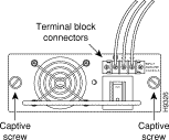
Step 4 Disconnect the DC input wires from the terminal block (see Figure 6).
Step 5 Use a screwdriver to loosen and remove the captive screws on the sides of the power supply (see Figure 6).
Step 6 Grasp the power supply handle with one hand and place your other hand underneath as you pull the power supply out of the bay (see Figure 7).

Step 7 If the power supply bay is to remain empty, install a blank power-supply filler plate (Cisco part number 700-00177-01) over the opening and secure it with the mounting screws. This protects the inner chassis from dust and prevents accidental contact with live voltage at the rear of the bay.
Step 8 To install a new power supply, follow Steps 1 through Step 7 in reverse order. After the installation is complete, perform the following to verify operation of the new supply:
Enter the show system command to display the power supply and Catalyst 5000 series switch status. The power supply status is listed in the PS-Status field of the show system command screen. Note that in the PS1- and PS2-Type fields, WS-C5068B is displayed—this is the model number for the DC power supply.
In the following example, the system status and other information is displayed:
Console> show system
PS1-Status PS2-Status Fan-Status Temp-Alarm Sys-Status Uptime d,h:m:s Logout
---------- ---------- ---------- ---------- ---------- -------------- ---------
ok         ok         ok         off        ok         1,01:24:18     none

PS1-Type   PS2-Type   Modem   Baud  Traffic Peak Peak-Time
---------- ---------- ------- ----- ------- ---- -------------------------
WS-C5068B   WS-C5068B   disable  9600   0%      0% Thu Mar 7 1996, 21:38:14

System Name              System Location          System Contact
------------------------ ------------------------ ------------------------
Abu-Catalyst-5000 5      Closet 202 1/F           Jeff x2529
Cisco Connection Online (CCO) is Cisco Systems' primary, real-time support channel. Maintenance customers and partners can self-register on CCO to obtain additional information and services.
Available 24 hours a day, 7 days a week, CCO provides a wealth of standard and value-added services to Cisco's customers and business partners. CCO services include product information, product documentation, software updates, release notes, technical tips, the Bug Navigator, configuration notes, brochures, descriptions of service offerings, and download access to public and authorized files.
CCO serves a wide variety of users through two interfaces that are updated and enhanced simultaneously: a character-based version and a multimedia version that resides on the World Wide Web (WWW). The character-based CCO supports Zmodem, Kermit, Xmodem, FTP, and Internet e-mail, and it is excellent for quick access to information over lower bandwidths. The WWW version of CCO provides richly formatted documents with photographs, figures, graphics, and video, as well as hyperlinks to related information.
You can access CCO in the following ways:
For a copy of CCO's Frequently Asked Questions (FAQ), contact cco-help@cisco.com. For additional information, contact cco-team@cisco.com.

![]()
![]()
![]()
![]()
![]()
![]()
![]()
![]()
Posted: Wed Aug 30 14:42:33 PDT 2000
Copyright 1989-2000©Cisco Systems Inc.