|
|

This note provides specific information regarding the configuration of Catalyst 3000 series equipment and software.
This configuration note introduces and describes the following features:
For the latest information on limitations or anomalies for the 2.2(1) software release refer to the "2.2(1) Version Software Release Note Catalyst 3000 Series".
For detailed information about configuring a Catalyst 3000 series switch, refer to the Installation and Configuration Guide for that model of the Catalyst switch.
Dynamic Inter-Switch Link Protocol (DISL) synchronizes the configuration of two interconnected Fast Ethernet interfaces into an ISL trunk. DISL minimizes VLAN trunk configuration procedures because only one end of a link needs to be configured as a trunk.
Use the following steps to configure trunking on ISL ports. For a complete description of VLANs, ISL, VTP, or port configuration, see the Installation and Configuration Guide of your model of Catalyst 3000 series switch.
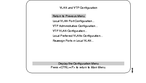
Step 1 Using the console, access the VLAN and VTP Configuration menu (see Figure 1).
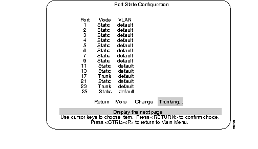
Step 2 At the VLAN and VTP Configuration menu, select the Local VLAN Port Configuration menu. The menu titled Port State Configuration is displayed (see Figure 2). This menu shows the VLANs that are carried on each port, and whether each port is a Trunk or is Static.
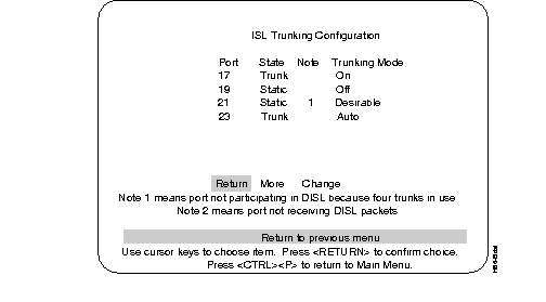
Step 3 From the Port State Configuration menu, choose the Trunking mode option to display the ISL Trunking Configuration screen. An example of this screen is shown in Figure 3. Use this screen to configure the DISL trunking mode for each ISL port.
The ISL Trunking Configuration screen displays:
The State and Note columns refresh automatically every few seconds to display the current state of each ISL port.
Step 4 To change the trunking mode of any port, select the Change option.
Step 5 When the prompt, "Enter port number to change" is displayed, enter the number of the ISL port that you want to change. If you enter a port number that isn't an ISL port, a warning message is displayed and you can enter another port number.
Step 6 Once you enter an ISL port number, four options representing the four DISL trunking modes are presented:
Step 7 Select one of these choices to change the chosen port to the selected trunking mode. This menu activates changes as soon as they are selected.
The On (or Off) trunking modes may cause configuration problems. The On or Off modes are intended to be used when an ISL port is connected to a neighbor port that you know does not support the DISL protocol. Since configurations can change, it is preferable to set the trunking mode to Auto or Desirable. If the neighbor port does not support DISL, the port functions as normal in Static mode.
Using the On trunking mode when DISL protocol is in use may lead to ISL-mode mismatches where one end of the link is trunking while the other end is not. If a trunk is desired, the Desirable trunking mode should be used.
Using the Off trunking mode is also not recommended when using DISL protocol. The risk of creating an ISL-mode mismatch is lower with the Off mode, but if a trunk is not desired, Auto mode should be used.
A 1 or a 2 is displayed in the Note column of the ISL Trunking Configuration screen to indicate why an ISL port is not a trunk when the configuration implies that it should be.
Note 1 is displayed if this port is not sending or processing DISL packets because it cannot be configured as a trunk port since it would exceed the limit of four trunk ports on that switch.
Note 2 means that the neighboring ISL port does not appear to be processing or sending DISL packets.
If the selected trunking mode causes a port to change between the Trunk and Static states, the console may operate slowly for a few seconds. The State and Note columns of the screen update automatically after the port changes between states.
The Port State Configuration screen also shows whether ports are trunks or not. This screen does not update automatically. To update the screen, exit and reenter this screen, or choose the More option.
There is a limit of four trunks that can be configured on a Catalyst 3000 series switch. This is not a factor on the Catalyst 3000 or 3100 because they have an installation limit of four high-speed ports. However, the Catalyst 3200 can have up to 14 high-speed ports installed (which can be configured with ISL). This means (potentially) more than four ports on that switch can be configured in trunking modes that allow a port to become a trunk (on, auto, and desirable). Once a Catalyst 3200 has four trunk ports configured, DISL packets are not sent or received on any static ISL ports. This prevents the Catalyst 3200's static ports, and any neighboring ISL ports, from switching into trunk ports (unless the On Trunking Mode is used as described in the section "Precautions for On Trunking Mode").
With versions 2.0 and 2.1 software releases, ISL ports have only two (non-dynamic) trunking modes: ISL Trunk and Non-ISL. With the 2.2(1) upgrade, ISL ports that were configured as ISL Trunk are automatically changed to the Desirable trunking mode and ISL ports that were configured as Non-ISL are automatically changed to the Auto trunking mode.
CGMP manages multicast traffic in Catalyst 3000 series switches by allowing directed switching of IP multicast traffic within a network.
CGMP offers the following benefits:
CGMP works in conjunction with Internet Group Management Protocol (IGMP) messages to dynamically configure Catalyst 3000 series switch ports so that IP multicast traffic is forwarded only to those ports associated with IP multicast hosts.
CGMP software components run on both the router and the Catalyst 3000 (and 5000) series switches. A CGMP-capable IP multicast router sees all IGMP packets and, therefore, can inform the Catalyst 3000 series switch when specific hosts join or leave IP multicast groups. When the CGMP-capable router receives an IGMP membership request packet, it creates a CGMP packet that contains the request type (either join or leave), the multicast group address, and the actual MAC address of the host. The router then sends the CGMP packet to a well-known address to which all Catalyst 3000 series switches listen. When a switch receives the CGMP packet, the processor interprets the packet and modifies the forwarding table. This process is performed automatically.
If a spanning-tree VLAN topology changes, the CGMP-learned multicast groups on the VLAN are purged. In this case, the CGMP-capable router will generate new multicast group information.
If a CGMP-learned port link is disabled for any reason, CGMP removes that port from any multicast group memberships.
When a particular host wants to join an IP multicast group, it sends an IGMP join message specifying its MAC address and which IP multicast group it wants to join. The CGMP-capable router then builds a CGMP join message and multicasts the join message to the well-known address to which the Catalyst 3000 series switches listen. Upon receipt of the join message, each Catalyst 3000 series switch searches a table to determine if it contains the MAC address of the host asking to join the multicast group. If a switch finds the host's MAC address in the table associating the MAC address with a port, the switch creates a multicast forwarding entry in the forwarding table. The host associated with that port will now receive multicast traffic for that multicast group. In this way, the table automatically learns the MAC addresses and port numbers of the IP multicast hosts.
The CGMP-capable router sends periodic multicast-group queries. If a host wants to remain in a multicast group, it responds to the query from the router. In this case, the router does nothing. If a host does not want to remain in the multicast group, it does not respond to the router query. If after a number of queries, the router receives no reports from any host in a multicast group, the router sends a CGMP command to the Catalyst 3000 series switch, telling it to remove the multicast group from its forwarding tables.
Leave-Processing allows IGMP hosts attached to the Catalyst switch to leave without causing any abnormal functionality of other hosts in the same or different groups.
In order for the a host to take full advantage of the Enhanced Leave Processing feature, it's IGMP implement must:
When a host decides to leave a group, it sends an IGMPv2 leave message on the network segment. The Catalyst switch intercepts and processes the leave request and sends (on the port from which it received the leave request) a query to the all-systems IP multicast group (224.0.0.1), with the Ethernet destination address being the group specific MAC address.
The Catalyst switch starts a timer in response to the host leaving the group on that port and waits for other members in the group, if any, to respond. The members who receive this query respond with an IGMP report which is forwarded to the CGMP router. The CGMP Router processes these IGMP reports and generates CGMP Join messages for each of the IGMP reports. If one of these CGMP Joins is for a host on a port and a group being left, the Catalyst cancels the associated timer before it expires. If the timer does expires, the port will be deleted as a port member of the group.
When there are no more non-router ports in the group, the Catalyst switch sends an IGMP leave for the group, to the multicast routers.
The Catalyst switch uses the IP address assigned to that VLAN on the switch as the source IP address for both the IGMP Query and IGMP Leave group messages that the switch generates as part of the Enhanced Leave Processing. If no IP address is assigned to the VLAN, the unspecified IP address of 0.0.0.0 is used. If this causes problems there are two solutions:
It is not possible to limit the destinations to which received multicast traffic will be forwarded when multicast traffic is received on a the Catalyst 3000 series ATM interface. Multicast traffic is forwarded (flooded) to all other ports in the switch or Stack that are in that same broadcast domain.
If it is felt that this situation will not occur on any of the VLANs that the ATM port carries, the ATM port may be deleted as a multicast router port.
Step 1 Access the Configuration Menu and select the CGMP Configuration menu. The CGMP Configuration menu is shown in Figure 4.
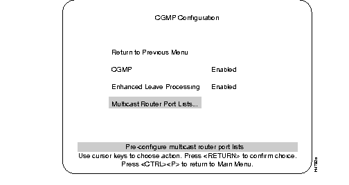
Step 2 Use the CGMP Configuration menu to enable or disable CGMP or Enhanced Leave Processing and to select ports to configure.
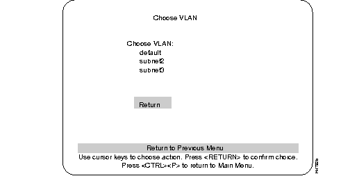
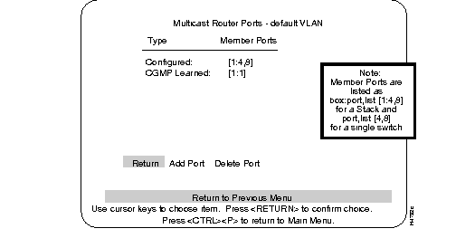
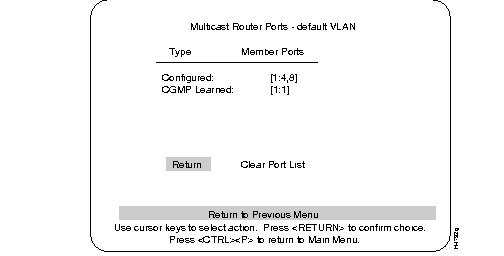
Step 3 Select "Multicast Router Ports..." to configure specific CGMP ports (use the Choose VLAN screen, as shown in Figure 5, to select the VLAN for configuring).The Multicast Router Ports (Figure 6) screen is displayed.
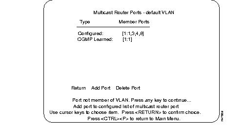
Step 4 Use the Multicast Router Ports screen (Figure 6) to add or delete a port.
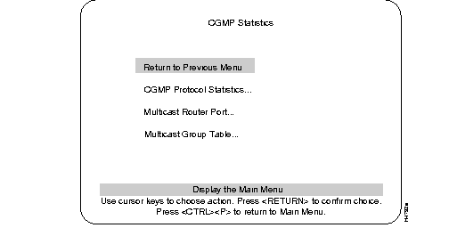
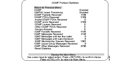
To view the status of CGMP, use the following CGMP statistic screens.The CGMP Statistic screen (Figure 8) is accessed from the main Statistics menu. From the CGMP Statistic menu, select the CGMP Protocol Statistics screen (Figure 9) to display the current status of CGMP information (after the Choose VLAN menu).
Use the following screen, Multicast Router Port Table (Figure 10), to view multicast router port lists.
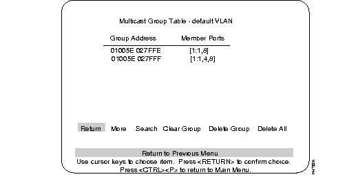
Use the Multicast Group Table (Figure 11) to view a multicast group table for a particular switch.
For service and support for a product purchased from a reseller, contact the reseller. Resellers offer a wide variety of Cisco service and support programs, which are described in the section "Service and Support" in the information packet that shipped with your product.
For service and support for a product purchased directly from Cisco, use CCO.
CCO is Cisco Systems' primary, real-time support channel. SMARTnet customers and partners can self-register on CCO to obtain additional information and services.
Available 24 hours a day, 7 days a week, CCO provides a wealth of standard and value-added services to Cisco's customers and business partners. CCO services include product information, product documentation, software updates, release notes, technical tips, the Bug Navigator, configuration notes, brochures, descriptions of service offerings, and download access to public and authorized files.
CCO serves a wide variety of users through two interfaces that are updated and enhanced simultaneously: a character-based version and a multimedia version that resides on the World Wide Web (WWW). The character-based CCO supports Zmodem, Kermit, Xmodem, FTP, and Internet e-mail, and it is excellent for quick access to information over lower bandwidths. The WWW version of CCO provides richly formatted documents with photographs, figures, graphics, and video, as well as hyperlinks to related information.
You can access CCO in the following ways:
For a copy of CCO's Frequently Asked Questions (FAQ), contact cco-help@cisco.com. For additional information, contact cco-team@cisco.com.
Please use CCO to obtain general information about Cisco Systems, Cisco products, or upgrades. If CCO is not accessible, contact 800 553-6387, 408 526-7208, or cs-rep@cisco.com.

|
|