|
|

For information about setting up a console session, refer to the "Planning for Configuration and Management" chapter.
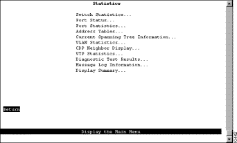
To access the Statistics Menu, select Statistics on the Main Menu. The Statistics Menu (Figure 8-1) is displayed.
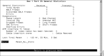
To view operating statistics for the Catalyst 3900, select Switch Statistics on the Statistics Menu. The Switch Statistics panel (Figure 8-2) is displayed. The information on the statistics panels is refreshed approximately every five seconds.
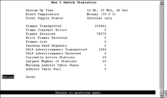
The following information is displayed on this panel:
| To | Select |
|---|---|
Reset the statistics displayed on the panel | Reset |
To view status information for each port of the Catalyst 3900, select Port Status on the Statistics Menu. The Port Status panel (Figure 8-3) is displayed.
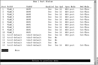
The following information is displayed on this panel:
You cannot change any information on this panel. To change the port parameters, refer to the "Configuring Port Parameters" section of the "Configuring the Catalyst 3900" chapter.
To view statistics for a specific port, select Port Statistics on the Statistics Menu and specify the port number. The Port Statistics panel (Figure 8-4) is displayed. If you specify the port number of an ATM port, the Port x ATM Statistics panel is displayed. See the "Viewing ATM Port Statistics" section for more information. If you specify the port number of an ISL port, the Port x ISL Statistics panel is displayed. See the "Viewing ISL Port Statistics" section for more information.
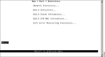
The following options are displayed on this panel:
To view general port statistics, select General Statistics on the Port Statistics panel. The Port x General Statistics panel (Figure 8-5) is displayed. The information on the statistics panels is refreshed approximately every five seconds.
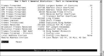
The following information is displayed on this panel:
| To | Select |
|---|---|
Reset the statistics displayed on the panel | Reset |
To view 802.5 port statistics, select 802.5 Statistics on the Port Statistics panel. The Port x 802.5 Statistics panel (Figure 8-6) is displayed. This panel is automatically refreshed every five seconds.
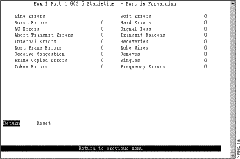
The following information is displayed on this panel:
| To | Select |
|---|---|
Reset the statistics displayed on the panel | Reset |
To view 802.5 port state information, select 802.5 State Information on the Port Statistics panel. The Port x 802.5 State Information panel (Figure 8-7) is displayed.
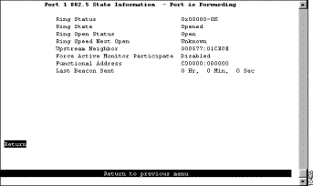
The following information is displayed on this panel:
0xnnnnn-text_string where nnnnn is a hexadecimal error code value, and text_string can be No Status, OK, or Error. Before an open is completed, the field has the value: 0x20000-No Status. If no problems are detected this field will display: 0x00000-OK. Other error conditions are indicated by: 0xnnnnn-Error.
To view 802.5 port dedicated Token Ring MAC information, select 802.5 DTR MAC Information on the Port Statistics panel. The Port x 802.5 DTR MAC Information panel (Figure 8-8) is displayed.
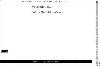
The following options are displayed on this panel:
If you select TXI Information on the Port x 802.5 DTR MAC Information panel, the Port x 802.5 DTR MAC TXI Information panel (Figure 8-9) is displayed.
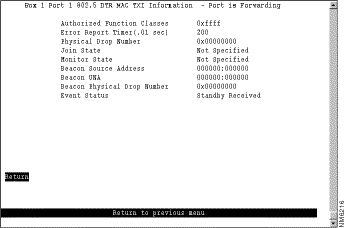
The following information is displayed on this panel:
If you select Station-CPort, the Port x 802.5 DTR MAC Station-CPort Information panel (Figure 8-10) is displayed.
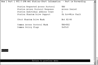
The following information is displayed on this panel:
To view soft error statistics for a port, select Soft Error Monitoring Statistics on the Port Statistics panel. The Soft Error Monitoring Statistics panel (Figure 8-11) is displayed.
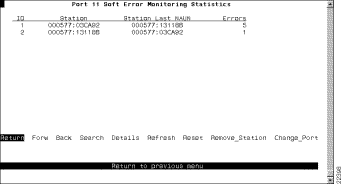
The following information is displayed on this panel:
| To | Select | Then |
|---|---|---|
Search for the statistics for a station | Search | Specify the MAC address of the station. |
View the statistic details for a station... | Details | Specify the MAC address or ID of the station. |
Issue a Remove Station MAC frame to remove a station from the ring... | Remove_Station | Specify the MAC address or ID of the station. |
View the soft error statistics for stations on another port... | Change_Port | Specify the port. |
Refresh the information displayed on the panel... | Refresh |
|
Reset the statistics displayed on the panel... | Reset |
|
 | Caution Selecting Remove_Station and specifying the MAC address or ID of a station issues a Remove Station MAC frame to that station and removes the station from the ring. Use this procedure with extreme caution. |
To view the details about the soft errors collected for a specific station, select Details on the Soft Error Monitoring Statistics panel and enter the MAC address or ID of the station. The Soft Error Monitoring Station Details panel (Figure 8-12) is displayed.
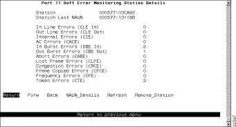
The following information is displayed on this panel:
| To | Select | Then |
|---|---|---|
Issue a Remove Station MAC frame to remove a station from the ring... | Remove_Station | Specify the MAC address or ID of the station. |
Display the detailed error counters for the station's NAUN | NAUN_Details |
|
Refresh the statistics displayed on the panel... | Refresh |
|
| Caution Selecting Remove_Station and specifying the MAC address or ID of a station removes that station from the ring. Use this procedure with extreme caution. |
To access statistics about the virtual ATM ports, select Port Statistics on the Statistics Menu panel and specify the port identifier of the ATM port. The Port x ATM Statistics panel (Figure 8-13) is displayed.
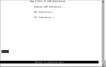
The following options are displayed on this panel:
To view general ATM statistical information, select General ATM Statistics on the Port x ATM Statistics panel. The Port x General ATM Statistics panel (Figure 8-14) is displayed.
The following information is displayed on this panel:
| To | Select |
|---|---|
Reset the ELAN statistics to 0... | Reset ELAN Statistics |
To view statistical information about the LEC, select LEC Statistics on the Port x ATM Statistics panel. The Port x LEC Statistics Menu panel (Figure 8-15) is displayed.
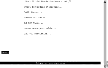
The following options are displayed on this panel:
To view forwarding statistics about frames received and transmitted on this port, select Frame Forwarding Statistics on the Port x LEC Statistics Menu panel. The Frame Forwarding Statistics panel (Figure 8-16) is displayed.
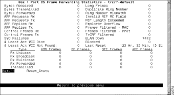
The following information is displayed on this panel:
| To | Select |
|---|---|
Reset the ELAN statistics for this port to 0... | Reset_Stats |
To view the status of the elements of this LEC, select LANE Status on the Port x LEC Statistics Menu panel. The Port x LANE Status panel (Figure 8-17) is displayed.
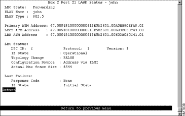
The following information is displayed on this panel:
To view the server VCC table, select Server VCC Table on the Port x LEC Statistics Menu panel. The Port x Server VCC Table panel (Figure 8-18) is displayed.
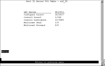
The following information is displayed on this panel:
To view the LE-ARP table, select LE-ARP Table on the Port x LEC Statistics Menu panel. The Port x LE-ARP Table panel (Figure 8-19) is displayed.
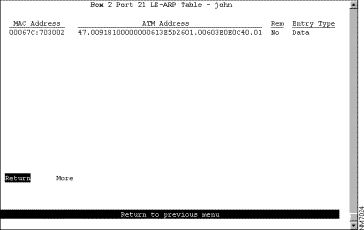
The following information is displayed on this panel:
To view the LE-ARP route descriptor table, select Route Descriptor Table on the Port x LEC Statistics Menu panel. The Port x Route Descriptor Table panel (Figure 8-20) is displayed.
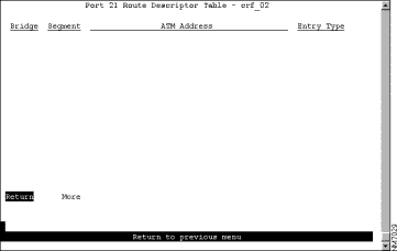
The following information is displayed on this panel:
To view VCC statistics for this LEC, select LEC VCC Statistics on the Port x LEC Statistics Menu panel. The Port x LEC VCC Statistics panel (Figure 8-21) is displayed.
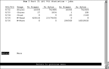
The following information is displayed on this panel:
To view statistical information about the VCCs associated with this port, select VCC Statistics on the Port x ATM Statistics panel. The Port x ATM VCC Statistics panel (Figure 8-22) is displayed.
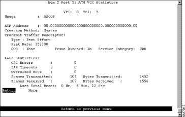
The following information is displayed on this panel:
To access statistics about the ISL ports, select Port Statistics on the Statistics Menu panel and specify the port identifier of the ISL port. The Port x ISL Statistics panel (Figure 8-23) is displayed.
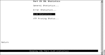
The following options are displayed on this panel:
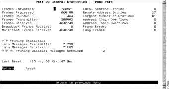
To view general statistical information about the traffic on the ISL port, select General Statistics on the Port x ISL Statistics panel. The Port x General Statistics panel (Figure 8-24) is displayed. As the Token Ring ISL module encapsulates Token Ring frames in Ethernet frames, the frame counters on this panel pertain to the Ethernet frames transmitted and received by the ISL module. The information on the statistics panels is refreshed approximately every five seconds.
The following information is displayed on this panel:
| To | Select |
|---|---|
Reset the statistics displayed on the panel | Reset |
To view statistical information about errors detected on the ISL port, select Error Statistics on the Port x ISL Statistics panel. The Port x Error Statistics panel (Figure 8-25) is displayed. The information on the statistics panels is refreshed approximately every five seconds.
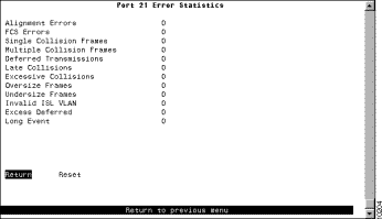
The following information is displayed on this panel:
| To | Select |
|---|---|
Reset the statistics displayed on the panel | Reset |
To view statistical information about traffic processed on each VLAN by the ISL port, select VLAN Statistics on the Port x ISL Statistics panel. The Port x VLAN Statistics panel (Figure 8-26) is displayed.
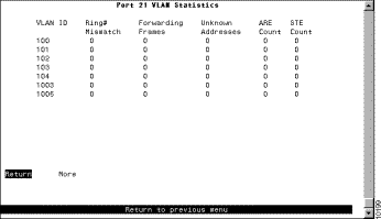
The following options are displayed on this panel:
| To | Select |
|---|---|
Reset the statistics displayed on the panel | Reset |
To view the VTP pruning status for the VLANs on the ISL port, select VTP Pruning VLAN Status on the Port x ISL Statistics panel. The Port x VTP Pruning Status panel (Figure 8-27) is displayed.
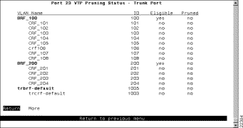
The following information is displayed on this panel:
To view address and route descriptor tables, select Address Tables on the Statistics Menu. The Address Tables panel (Figure 8-28) is displayed.
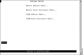
The following options are displayed on this panel:
To view all entries in the master address table, select Master Address Table on the Address Table panel. The Master Address Table panel (Figure 8-29) is displayed. The master address table can contain up to 10,000 entries.
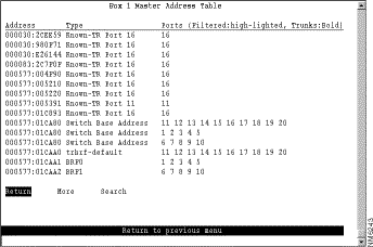
The following information is displayed on this panel:
| To | Select | Then |
|---|---|---|
Search for a specific MAC address | Search | Specify the address. |
To view all the route descriptors (and their associated ports) that have been learned by the Catalyst 3900, select Master Route Descriptor Table on the Address Tables panel. The Master Route Descriptor Table panel (Figure 8-30) is displayed. These descriptors are contained within the 10,000 entries allowed for the master address table.
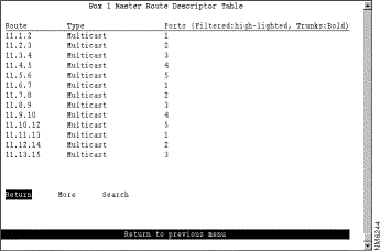
The following information is displayed on this panel:
local_segment_number.bridge_number.remote_segment_number
| To | Select | Then |
|---|---|---|
Search for a specific route descriptor | Search | Specify the route descriptor. |
To view the entries in the address table for each VLAN, select VLAN Address Table on the Address Tables panel and select the desired TrCRF. The VLAN Address Table panel (Figure 8-31) is displayed. The entries are listed in the order in which they were learned.
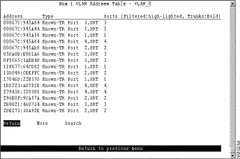
The following information is displayed on this panel:
| To | Select | Then |
|---|---|---|
Search for a specific MAC address | Search | Specify the address. |
To view the entries in the route descriptor table for each VLAN, select VLAN Route Descriptor Table on the Address Table panel and specify the desired TrCRF. The VLAN Route Descriptor Table panel (Figure 8-32) is displayed.
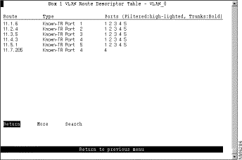
The following information is displayed on this panel:
local_segment_number.bridge_number.remote_segment_number
| To | Select | Then |
|---|---|---|
Search for a specific route descriptor | Search | Specify the route descriptor. |
To display the spanning-tree parameters for a TrBRF, select Current Spanning Tree Information on the Statistics Menu and specify the desired TrBRF. The Current Spanning Tree Information panel (Figure 8-33) is displayed.
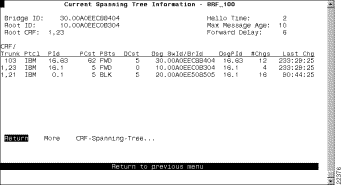
The following information is displayed on this panel:
You cannot change any information on this panel. To change the spanning-tree parameters, refer to the "Configuring Spanning-Tree Parameters" section of the "Configuring the Catalyst 3900" chapter.
To display the spanning-tree parameters for a TrCRF that belongs to the currently displayed TrBRF, select CRF-Spanning-Tree on the Current Spanning Tree Information panel for a TrBRF and specify the desired TrCRF. The Current Spanning Tree Information panel (Figure 8-34) is displayed.
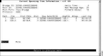
The following information is displayed on this panel:
You cannot change any information on this panel. To change the spanning-tree parameters, refer to the "Configuring Spanning-Tree Parameters" section of the "Configuring the Catalyst 3900" chapter.
The Catalyst 3900 provides statistical information for both TrCRFs and TrBRFs. To access statistics for VLANs, select VLAN Statistics on the Statistics Menu.
To view statistics for a TrCRF, select VLAN Statistics on the Statistics Menu, select TrCRF, and then select the desired TrCRF. The VLAN Statistics panel (Figure 8-35) is displayed.
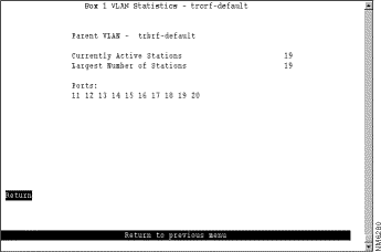
The following information is displayed on this panel:
To view statistics for a TrBRF, select VLAN Statistics on the Statistics Menu, select TrBRF, and then select the desired TrBRF. The VLAN Statistics panel (Figure 8-36) is displayed.
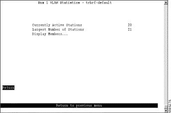
The following information is displayed on this panel:
| To | Select | Then |
|---|---|---|
Display a list of the TrCRFs associated with this TrBRF | Display Members | Refer to the "Displaying the TrCRFs of a TrBRF" section. |
To display the TrCRFs associated with a TrBRF, select Display Members on the VLAN Statistics panel. The VLAN Statistics panel (Figure 8-37) is displayed.
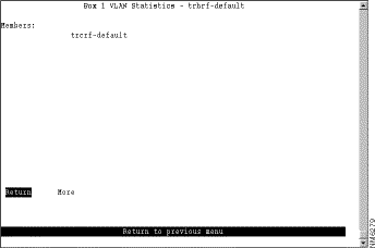
This panel lists VLAN names of all the TrCRFs associated with the parent TrBRF.
To view information about other Cisco devices with which the Catalyst 3900 is communicating via CDP, select CDP Neighbor Display on the Statistics Menu. The CDP Neighbor Display panel (Figure 8-38) is displayed.
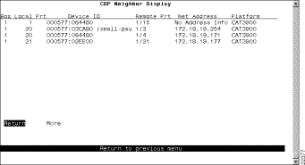
The following information is displayed on this panel:
If the switch is operating in Server mode, an advertisement is sent across the trunk port when the following events occur:
Each advertisement consists of one Summary Advertisement immediately followed by zero or more Subset Advertisements. The number of Subset Advertisement messages that follow a Summary Advertisement depends on the reason for sending the advertisement.
An Advertisement Request is sent after a reboot. Also, if any of the following actions occur then a timer is started:
If the timer expires before either an Advertisement Request or Summary Request is received, then an Advertisement Request is sent.
When an Advertisement Request is sent because some Subset Advertisement messages were missed, the Advertisement Request is set to request only those VLANs that were missed.
To view VTP message counters, select VTP Statistics on the Statistics Menu. The VTP Statistics panel (Figure 8-39) is displayed.
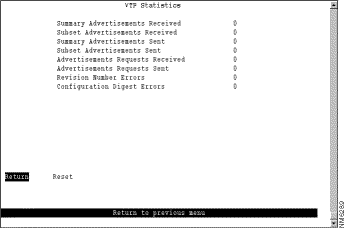
The following information is displayed on this panel:
| To | Select |
|---|---|
Reset the statistics displayed on the panel | Reset |
To view the results of the most recent power-on diagnostics, select Diagnostic Test Results on the Statistics Menu. The Diagnostic Test Results panel (Figure 8-40) is displayed.
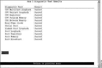
This panel displays a list of the self-diagnostic tests that the Catalyst 3900 performs and the result of each. For information about running the diagnostic tests, refer to the "Resetting the Catalyst 3900" chapter.
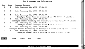
To view the message log, select Message Log on the Statistics Menu. The Message Log Information panel (Figure 8-41) is displayed. The data on this panel is useful to technical experts when they are solving complex problems.
The log can maintain a list of up to 200 messages. Once 200 messages have been logged, new messages received will be added to the end of the log and the oldest message will be deleted from the panel. The log entry numbers continue to increment, indicating the total number of messages received. The first (oldest) seven messages are displayed. You can use the options at the bottom of the panel to move through the message log.
The following information is displayed on this panel:
| To | Select |
|---|---|
Page forward in the message log... | More |
Move to the end of the message log... | End |
Return to the beginning of the message log... | Start |
Delete the contents of the message log | Clear |
To display a summary of the configuration of your Catalyst 3900, select Display Summary on the Statistics Menu. The summary information is displayed on the console panel (Figure 8-42).
You can scroll through the information to view your current configuration parameter settings. The summary includes:
To exit from the configuration summary and return to the Statistics menu, wait until the configuration summary dump is complete and then press any key.
![]()
![]()
![]()
![]()
![]()
![]()
![]()
![]()
Posted: Tue Oct 12 11:58:08 PDT 1999
Copyright 1989-1999©Cisco Systems Inc.