|
|

Read this chapter before using the Catalyst 3900 in your network. This chapter contains information and instructions that are useful in preparation for using the Catalyst 3900 in your network. This chapter provides the following information:
The Catalyst 3900 can be managed via an SNMP manager. The Catalyst 3900 supports 12 Management Information Bases (MIBs). Nine of the MIBs are standard MIBs, which are defined by RFCs and are included with most SNMP management applications. Three of the MIBs are private MIBs.
For more information about the MIBs supported, see the "SNMP-Based Management" section of the "Introduction to the Catalyst 3900" chapter.
To access the MIBs via FTP:
Step 1 Enter the ftp cco.cisco.com command.
Step 2 Log in with the username anonymous and enter your e-mail address when prompted for the password.
Step 3 Enter the cd pub/mibs command to go to the directory that contains the MIB files.
Step 4 Enter the get README command to obtain the README file containing a description of the Cisco Systems public MIB area.
To determine the MIBs supported for each Cisco product, go to the supportlists subdirectory where you will find directories for all Cisco products. Refer to the supportlist.txt file in each directory, as necessary, to determine the MIBs supported on that platform, for each Cisco IOS software release, and the location of the desired MIB file. Cisco IOS MIB files are in the v1 and v2 subdirectories. You can then use the ftp command get mib-filename to retrieve the MIB file.
A description of issues you might encounter when loading Cisco MIBs into your NMS is located at ftp://www.cisco.com/pub/mibs/app_notes/mib-compliers.
To access the MIBs on CCO via the WWW, use this URL: http://www.cisco.com/public/mibs or ftp://www.cisco.com/pub/mibs.
You can establish either a local or remote connection to the Catalyst 3900. For a local connection, you directly connect a PC, or other DTE, to the EIA 232 port on the Catalyst 3900. For a remote connection, connect a modem to the EIA 232 port then dial in from your remote workstation. For information about the cabling requirements for the EIA 232 port, see the "Cable and Pin Information" appendix.
To connect a local terminal to the Catalyst 3900, perform the following steps:
Step 1 Start your terminal emulation software on the PC or other DTE to which you will connect the Catalyst 3900.
Step 2 Set the terminal emulation settings using the parameters listed in Table 5-1.
If you are using the Microsoft Windows terminal emulation, disable the "Use Function, Arrow, and Ctrl Keys for Windows" option, located in the Terminal Preferences menu under Settings.
Baud rate | 1200, 2400, 4800, 9600, 19200, 38400, or 57600 (9600 is the default) |
Parity | None |
Data bits | 8 |
Stop bits | 1 |
Handshaking | None |
Terminal emulation | VT100 |
Duplex | Full |
Software flow control (XON/XOFF) | Off |
Hardware flow control (RTS/CTS) | Off |
Line wrap | Off |
Screen scroll | On |
CR translation | CR |
Backspace (BS) translation | Destructive |
Break length (ms) | 350 |
Enquiry (ENQ) | Off |
EGA/VGA true underline | Off |
Terminal width | 80 |
ANSI 7- or 8-bit commands | 7 |
Step 3 Connect the EIA 232 port on the Catalyst 3900 to your PC or DTE device using a null-modem cable or straight-through cable and null-modem adapter. The Catalyst 3900 has a 9-pin male connector. For pin-out and cable information, refer to the "Cable and Pin Information" appendix.
Step 4 Plug in the Catalyst 3900 if you have not already done so, or press the Reset button. The Catalyst 3900 does not have a power switch; the Catalyst 3900 is powered on when you plug in the power cord. When the Catalyst 3900 is powered on, it performs a series of self-test diagnostics. (For more information about these diagnostic tests, refer to the "Resetting the Catalyst 3900" chapter.)
Step 5 When diagnostics are complete, continue with the steps in the "Using the Console Panels" section.
Step 1 Set up your modem according to its instructions.
Step 2 Connect the cable from the EIA 232 port on the modem to the EIA 232 port on the Catalyst 3900.
Step 3 Set the modem as follows:
Step 4 Start your terminal emulation software on the PC or other DTE to which you will be connecting the Catalyst 3900.
Step 5 Set the terminal using the emulation parameters listed in Table 5-1.
Step 6 Dial in to the Catalyst 3900 modem from your remote site.
Step 7 Continue with the steps in the "Using the Console Panels" section.
There are three types of communications problems that you might encounter when establishing a serial link connection: no communication, corrupted communication, and dropped characters. This section suggests steps to resolve these problems. In some cases, you are instructed to alter the configuration of the connection at the terminal or at the Catalyst 3900. For information about altering the configuration of your terminal emulator, refer to the documentation that accompanied your emulation program. For information about altering the configuration of the connection at the Catalyst 3900, refer to the "Customizing the Console Session" section.
If no communication is established, perform the following steps to determine the cause:
Step 1 Check the cables and physical connections. Ensure that you are using the proper cable and adapter.
Step 2 Check the handshaking configuration at the terminal and the Catalyst 3900. Handshaking at the Catalyst 3900 is controlled by the Hardware Flow Control field on the Serial Link Configuration panel. Refer to the "Customizing the Serial Link" section for more information.
 | Caution Hardware handshaking must be turned on at the Catalyst 3900 and at the terminal. You must also be using a 7- or 9-wire cable to the terminal. If hardware handshaking is off and you are using a 3-wire cable, a catastrophic failure of the Catalyst 3900 can occur. |
Step 3 If the Catalyst 3900 has just been installed and is not yet in use, reset the Catalyst 3900. Resetting the Catalyst 3900 while it is in use will disrupt your network.
Step 4 If the problem continues, contact the Cisco Technical Assistance Center (TAC).
If communication is established but the data displayed is corrupted, perform the following steps:
Step 1 Ensure that the baud rate set at the Catalyst 3900 matches the rate set at the terminal.
Step 2 Verify the configuration of the terminal emulation, specifically:
Step 3 If the Catalyst 3900 has just been installed and is not yet in use, reset the Catalyst 3900.
 | Caution Resetting the Catalyst 3900 while it is in use will disrupt your network. |
Step 4 If the problem continues, contact the Cisco TAC.
If communication is established but some of the characters appear to be dropped or lost:
Step 1 Reduce the baud rate configured at the Catalyst 3900. We suggest a baud rate of 9600.
Step 2 Enable the software handshaking feature. Handshaking at the Catalyst 3900 is controlled by the Software Flow Control field on the Serial Link Configuration panel. Refer to the "Customizing the Serial Link" section for more information.
 | Caution Hardware handshaking must be turned on at the Catalyst 3900 and at the terminal. You must also be using a 7- or 9-wire cable to the terminal. If hardware handshaking is off and you are using a 3-wire cable, a catastrophic failure of the Catalyst 3900 can occur. |
Step 3 If the problem continues, contact the Cisco TAC.
To establish a Telnet session to the Catalyst 3900:
Step 1 Set the IP State on the IP Configuration panel to "BootP When Needed" or "BootP Always".
Step 2 Configure your Telnet client to use a VT100/VT220 compatible setup.
Step 3 Telnet to the Catalyst 3900 using its assigned IP address. For information about assigning an IP address to the Catalyst 3900, refer to the "Configuring IP Information" section of the "Configuring the Catalyst 3900" chapter.
Step 4 Continue with the Telnet session using the steps in the "Using the Console Panels" section.
To terminate the Telnet session, press Ctrl-B or use the method provided by the Telnet application.
If you attempt to access a console panel that is already accessed by another Telnet or serial link session, the message "Console is currently in use" is displayed.
If you are using a Telnet session to access the console panels, be aware of the following limitations:
A Telnet session can be terminated involuntarily from the console or as a result of certain configuration changes.
When the console is idle and Telnet is active, a user at the console can terminate the Telnet session without warning (refer to the "Customizing and Managing the Telnet Sessions" section).
Also, the Telnet session will end if you disable the port through which you are accessing the Catalyst 3900 and might end if a user changes any of the following information for the port through which you are accessing the Catalyst 3900:
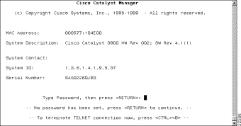
After you have established a connection to the Catalyst 3900 via a serial link or a Telnet session, the Copyright panel (Figure 5-1) is displayed.
To access the console panels, do the following:
Step 1 Type the password (if one has been configured). The default is that no password is set.
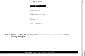
Step 2 Press Enter to advance to the Cisco Catalyst 3900 Main Menu panel (Figure 5-2).
From this menu you can:
Step 3 Use your cursor to select an item and then press Enter.
As you move through the console panels, follow these guidelines:
1-3 5 7-9
1-3,5,7-9
To customize your console session, select Configuration on the Main Menu and then select Console Configuration on the Configuration Menu. The Console Configuration panel (Figure 5-3) is displayed.
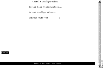
The Console Time-Out information is displayed on this panel. The Console Time-Out is the time, in minutes, that the console session can remain inactive before it times out. Unsaved entries are lost when the console times out. Valid values are 0 through 1440. The default is 5. A value of 0 means the console will not time out
.
| To | Select | Then |
|---|---|---|
Change the console time-out... | Console Time-Out | Specify the new value. |
Specify parameters for a console session via a serial link... | Serial Link Configuration | Refer to the "Customizing the Serial Link" section. |
Specify parameters for a console session via Telnet... | Telnet Configuration | Refer to the "Customizing and Managing the Telnet Sessions" section. |
Save your changes... | Return |
|
To view and change the parameters for a serial link console session, select Serial Link Configuration on the Console Configuration panel. The Serial Link Configuration panel (Figure 5-4) is displayed.
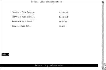
The following information is displayed on this panel:
| To | Select | Then |
|---|---|---|
Change the current settings... | The appropriate parameter... | Specify the new value. |
Save your changes... | Return |
|
To view and change the parameters for a Telnet console session, select Telnet Configuration on the Console Configuration panel. The Telnet Configuration panel (Figure 5-5) is displayed.
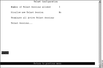
The following information is displayed on this panel:
| To | Select | Then |
|---|---|---|
Change the current settings... | The appropriate parameter... | Specify the new value. |
Stop all active Telnet sessions... | Terminate All Active Telnet Sessions |
|
Display information about a specific Telnet session... | Telnet Sessions | Refer to the "Managing Individual Telnet Sessions" section. |
Save your changes... | Return |
|
To display information about or to close any active Telnet session, select Telnet Sessions from the Telnet Configuration panel. The Telnet Sessions panel (Figure 5-6) is displayed.
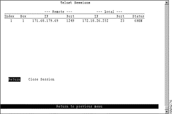
The following information is displayed on this panel:
| To | Select | Then |
|---|---|---|
Stop a specific Telnet session... | Close Session | Specify the index number of the session to close. |
Save your changes... | Return |
|
![]()
![]()
![]()
![]()
![]()
![]()
![]()
![]()
Posted: Tue Oct 12 11:52:39 PDT 1999
Copyright 1989-1999©Cisco Systems Inc.