You might not have to configure the Catalyst 2600 for it to work in your network; it is shipped with default configuration parameters and can function with these defaults. However, if you want or need to alter the configuration of the Catalyst 2600, you can use a console session. This chapter provides information on the following:
To alter the configuration of your Catalyst 2600, do the following:
Step 1 Obtain a completed Catalyst 2600 Configuration Parameters Worksheet. Configuration Parameters worksheets are typically completed by a network administrator. Each worksheet or section of the worksheet corresponds to a console configuration panel that is accessed from the Configuration Menu.
Step 2 Establish a console session, if one has not already been established. (For information about establishing a console session, refer to the section "Planning for Configuration and Management".)
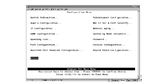
Step 3 At the Main Menu, select Configuration. The Configuration Menu (Figure 5-1) is displayed.
Figure 5-1: Configuration Menu Panel
Step 4 Select the menu option you want.
Step 5 Change or enter values according to the configuration parameters worksheets.
Step 6 When you have changed or entered all of the required configuration parameters, save the changes and return to the Main Menu. Configuration is complete.
As you move through the console panels, follow these guidelines:
- To select a menu or action item, move the cursor to the item and press ENTER.
- In general:
- To make changes to a parameter, move the cursor to the parameter name and press ENTER. You will then be prompted to enter the new data or select from a list of valid choices.
- To make changes to a list entry, select Change and specify the entry identifier (index number). You will then be prompted to enter the new data or select from a list of valid choices. Some list entries consist of multiple parameters. To retain the current value of any parameter, enter a null value at the prompt.
- To save in NVRAM any changes made to the configuration panels, you must select Return.
- To return to the main menu, press CTRL-N. Changes made to the current panel will not be saved.
- To refresh the console panel at any time, press CTRL-L.
- In some cases, more information is available than can be displayed on the panel. To scroll to the next panel of information, select More.
To view or change basic switch information, such as the MAC address, system name, system location, or system contact, select Switch Information on the Configuration Menu. The Switch Configuration panel (Figure 5-2) is displayed.
Figure 5-2: Switch Information Panel
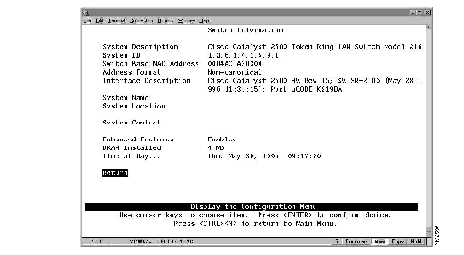
The following information is displayed on this panel:
- System Description--The full name and version identification of the system's hardware type. Information in this field cannot be changed.
- System ID--The unique identification code for this Catalyst 2600 that was assigned at the factory. This code serves a purpose similar to that of a serial number. Information in this field cannot be changed.
- Switch Base MAC Address--The MAC address of the Catalyst 2600. Information in this field cannot be changed.
- Address Format--The format used for MAC addresses (canonical or non-canonical). Canonical format is typically used in Ethernet and is also known as least significant bit first. Non-canonical is typically used in Token Ring networks and is also known as most significant bit first.
- Interface Description--The hardware and microcode version of the Catalyst 2600. Information in this field cannot be changed.
- System Name--The locally assigned name of this Catalyst 2600.
- System Location--The location information for this Catalyst 2600.
- System Contact--The name of system contact for this Catalyst 2600.
- Enhanced Features--The state of the enhanced feature set. Information in this field cannot be changed.
- DRAM Installed--The number of megabytes of memory installed. Information in this field cannot be changed.
- Time of Day--The time according to the internal clock of the Catalyst 2600.
|
To
| Select
| Then
|
|---|
| Change the current settings...
| The appropriate parameter...
| Specify the new value.
|
| Save your changes...
| Return
|
|
You can partition a single Catalyst 2600 into multiple domains. Each domain acts like a separate switch, or virtual LAN (VLAN). A domain can be configured with its own IP address and managed with SNMP. Any domain can participate independently in the Spanning-Tree Protocol. Once domains have been established, packets are forwarded between ports belonging to the same domain only.
To view the current port assignments or to assign the ports of the Catalyst 2600 to different domains, select Domain Configuration on the Configuration Menu. The Domain Configuration panel (Figure 5-3) is displayed.
Figure 5-3: Domain Configuration Panel
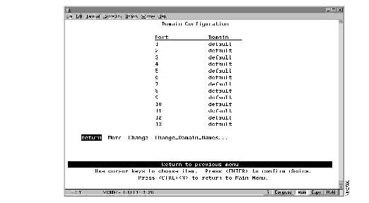
The following information is displayed on this panel:
- Port--The number of the port that you want to assign to a domain. All ports are initially assigned to domain 0 (named "default").
- Domain--The domain (0-7) assigned to a port.
|
To
| Select
| Then
|
|---|
| Change the domain assignment for a port...
| Change
| Specify the appropriate port and the new domain.
|
| Change the name associated with a domain...
| Change_Domain_Names
| Refer to "Changing Domain Names".
|
| Save your changes...
| Return
|
|
 | Caution Every port in each affected domain will be reset when the changes are saved. This is potentially disruptive. If you are using Telnet to access the configuration panels, and you are connected via an affected port, you will loose your Telnet connection. |
To change the name associated with a domain (1-7), select Change_Domain_Names on the Domain Configuration panel. The Domain Names panel (Figure 5-4) is displayed.
Figure 5-4: Domain Names Panel
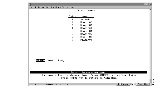
The following information is displayed on this panel:
- Index--The identifier of the domain name entry.
- Name--The 1- to 16-character domain name.
|
To
| Select
| Then
|
|---|
| Change the name associated with a domain...
| Change
| Specify the index number of the entry and the new domain name.
|
| Save your changes...
| Return
|
|
To view or change IP information associated with a domain, such as the IP address, subnet mask, or IP state, or to send PINGs, select IP Configuration on the Configuration Menu. The IP Configuration panel (Figure 5-5) is displayed.
Figure 5-5: IP Configuration Panel
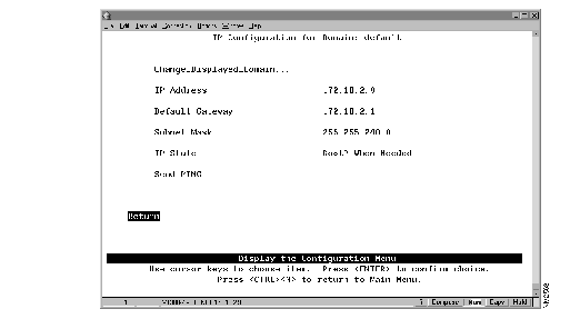
The following information is displayed on this panel:
- IP Address--The current IP address for the domain. The default IP address is 0.0.0.0.
- Default Gateway--The default gateway address. The default gateway address is 0.0.0.0.
- Subnet Mask--The current subnet mask. The default subnet mask is 0.0.0.0.
- IP State--The current IP state. The default is "BootP When Needed."
- IP Disabled--The domain will not process any IP or Address Resolution Protocol (ARP) frames it receives. It will not respond to SNMP, PING, Telnet, or ARP frames that are received.
- BootP When Needed--If the IP address is 0 (0.0.0.0), BootP requests will be broadcast by the Catalyst 2600 in an effort to learn its IP address. All other IP functions are disabled until it receives a reply. If a non-0 IP address has been configured (and stored in NVRAM), IP is enabled for the domain and will function immediately.
- BootP Always--IP is enabled for the domain but will not function until a BOOTP reply has been received. If a non-0 IP address for the domain is stored in NVRAM, it will be cleared to 0 when the Catalyst 2600 is booted.
When you select either of the BootP options in the preceding list, the Catalyst 2600 repeats BootP requests at regular intervals, beginning at 1 second intervals and eventually decreasing to 5 minute intervals until it has received a valid response.
The parameters in a BootP response that are recognized and recorded in NVRAM are:
- IP Address
- Default Gateway
- Subnet Mask
- TFTP Bootfile Name
- TFTP Server Address
The BootP requests will also cease if a valid IP address is configured via the console panels or if the IP state is set to IP Disabled. Once the Catalyst 2600 stops sending BootP requests on a domain, it does not resume sending requests or recognize BootP responses on that domain unless the Catalyst 2600 is reset.
For more information about BootP, refer to the appendix "Understanding BootP."
| To
| Select
| Then
|
|---|
| Change the current settings...
| The appropriate parameter...
| Specify the value.
|
| View or change IP information associated with a different domain...
| Change_Displayed_Domain
| Specify the domain.
|
| Verify the network availability of a particular resource...
| Send PING
| Specify the IP address of the resource.
|
| Save your changes...
| Return
|
|
Note IP addresses are always entered in dotted-decimal notation (a set of 4 decimal numbers from 0 through 255 separated by periods). The default is 0.0.0.0. If the default is used, no SNMP management will be available.
To view or change the spanning-tree parameters associated with a domain, such as the switch priority and the port path cost, select Spanning Tree on the Configuration Menu. The Spanning Tree panel (Figure 5-6) is displayed.
Figure 5-6: Spanning Tree Panel
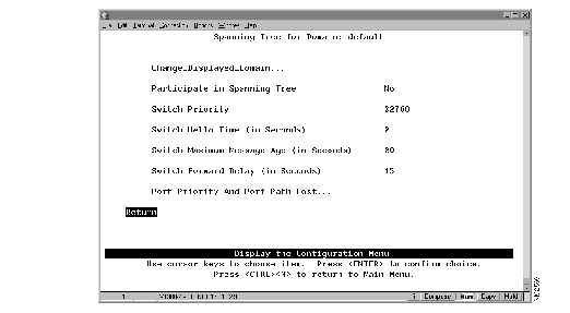
The following information is displayed on this panel:
- Participate In Spanning Tree--Indicates whether this domain participates in the Spanning-Tree Protocol (802.1d or No). Specify 802.1d to participate in the Spanning-Tree Protocol. If you specify No, the remaining values on the menu will be saved but will have no effect. The default is No.
- Switch Priority--The priority value for this Catalyst 2600 (0 through 65,535). The lower the priority value, the higher the priority. The bridge or switch with the lowest priority value in a spanning tree becomes the root. The default is 32,768. (To change individual port priorities, select Port Priority and Port Path Cost.)
- Switch Hello Time (in seconds)--The time the Catalyst 2600 waits before sending the next configuration message when this Catalyst 2600 is the root switch. The default is 2.
- The minimum value is 1. The maximum value is the lower of 10 or:
- (Switch Maximum Message Age ³ 2) -1
- The valid range for this parameter is displayed when you select Switch Hello Time.
- Switch Maximum Message Age (in seconds)--The maximum message age used when this Catalyst 2600 is the root switch. This parameter sets the time at which the configuration message used by the spanning-tree algorithm should be discarded. The default is 20. The minimum value is the higher of 6 or:
- 2 x (Switch Hello Time + 1)
- The maximum cannot be more than the lower of 40 or:
- 2 x (Switch Forward Delay -1)
- The range limits that appear when you select this parameter are calculated using the values currently selected for Switch Hello Time and Switch Forward Delay.
- Switch Forward Delay (in seconds)--The time the Catalyst 2600 waits between transitions from listening to learning and from learning to forwarding. The default is 15. The minimum is the larger of 4 or:
- (Switch Maximum Message Age ³ 2) + 1
- The maximum is 30.
- The lower range limit that appears when you select this parameter reflects the value currently selected for Switch Maximum Age.
|
To
| Select
| Then
|
|---|
| Change the current settings...
| The appropriate parameter...
| Specify the value.
|
| View or change the spanning-tree parameters for a different domain...
| Change_Displayed_Domain
| Specify the domain.
|
| View or change the priority and path cost for a port that participates in the Spanning-Tree Protocol...
| Port Priority and Port Path Cost
| Refer to "Specifying Port Priority and Port Path Cost".
|
| Save your changes...
| Return
|
|
To view or change the priority and path cost associated with a port, select Port Priority and Port Path Cost on the Spanning Tree panel. The Port Priority and Port Path Cost panel (Figure 5-7) is displayed.
Figure 5-7: Port Priority and Port Path Cost Panel
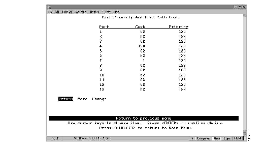
The following information is displayed on this panel:
- Port--The identifier of the port.
- Cost--The cost associated with the port. The Spanning-Tree Protocol uses port path costs to determine which port to select as a forwarding port. Therefore, lower numbers should be assigned to ports attached to faster media (such as FDX or TokenChannel), and higher numbers should be assigned to ports attached to slower media. The possible range is 1 to 65,535. The default is 62. The recommended path cost is:
- 1000 ³ LAN speed in Mbps
- Priority--The priority associated with the port. The port with the lowest priority value has the highest priority and will forward the spanning-tree frames. The default is 128. The possible range is 0 through 255 (decimal). If all ports have the same priority value, the lowest port number forwards the spanning-tree frames.
|
To
| Select
| Then
|
|---|
| Change the cost associated with a port...
| Change
| Specify the port number, select Cost, and specify the new value.
|
| Change the priority associated with a port...
| Change
| Specify the port number, select Priority, and specify the new value.
|
| Save your changes...
| Return
|
|
To view or change the configuration parameters of a port such as the mode, type, and speed, select Port Configuration on the Configuration Menu. The Port Configuration panel (Figure 5-8) is displayed.
Figure 5-8: Port Configuration Panel
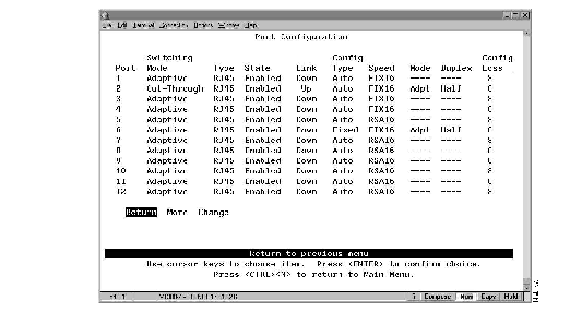
The following information is displayed on this panel:
- Port--The identifier of the port.
- Switching Mode--The switching mode of the port. The possibilities are:
- Cut-Through--The highest-speed switching mode.
- Store-and-forward--Provides improved error isolation at the expense of some speed.
- Adaptive Cut-Through--The Catalyst 2600 operates in cut-through mode until it reaches the error rate high threshold set in the Switching Mode Threshold panel (refer to the section "Configuring Switching Mode Thresholds"). Then, the Catalyst 2600 changes to store-and-forward mode. It will change back to cut-through mode when it falls below the error rate low threshold. This is the default.
- Type--The port type. Ports 1 through 16 are RJ45. If a Universal Feature Card is installed, each of its ports and port types are listed here.
- State--The operational status of the ports. The default is Enabled.
- Link--Indicates whether the port is Up (open) or Down (closed).
- Configuration Type--The type of configuration mechanism used for the port. The default is Auto.
- Auto--Speed, Mode, and Duplex are automatically set by the Catalyst 2600 through a connection negotiation process.
Note When a port with a configuration type of Auto discovers a connection to shared media, it will open and insert into the ring. If this port is the first station to enter the ring, the port will close as it will be unable to detect the ring speed.
- Fixed--Allows you to manually set Speed, Mode, and Duplex. If you are connecting two switches, it is recommended that you fix the configuration of one of the connected ports. This will save connection time by enabling the Catalyst 2600 to by-pass the connection negotiation process.
Note If you plan to attach the Catalyst 2600 to other manufacturers' switch ports that are configured for fixed, full-duplex only operation and that conform to the Dedicated Token Ring Draft Standard, Version 3, you must manually configure (Fixed) the affected ports of the Catalyst 2600.
- Speed--The speed of the port in Mbps. The prefix RSA (ring speed adjust) means the speed was automatically sensed and set by the Catalyst 2600. The prefix FIX means the speed was set to a fixed value via configuration. If the port is configured to use Adaptive Cut-Though mode, FIX16 is the only speed that you can specify.
- Mode--Whether the port is used for shared or dedicated media.
- Port Mode--In port mode only a dedicated connection to a station is supported. The Tx/Rx pinouts are the same as a concentrator's.
- Adapter Mode--In adapter mode, the port operates like a station. The connection may be dedicated or shared. The Tx/Rx pinouts are the same as an adapter's.
- Duplex--Indicates whether the port is operating in full or half duplex mode. Changes to the duplex settings are made immediately by the Catalyst 2600.
Note The Catalyst 2600 supports the FDX protocol with an automatic drop-back to half-duplex (as defined by IEEE 802.5R). Therefore, if a station that is directly attached to a port configured for full-duplex attempts to open in half-duplex mode, the port will drop back and operate in half-duplex mode.
- Configuration Loss--The configuration loss threshold. Configuration loss occurs when a port completes a connection, allows data traffic to flow, and subsequently closes. This threshold is used to control the number of configuration losses that can occur within a specified time. When the threshold is exceeded, the port is disabled and must be enabled via this panel or an SNMP manager. The default is 8. The range is 1 through 100.
Note If you change any configuration parameters of a connected port, the port will close and reopen and you will loose all address information and statistics for that port.
| To
| Select
| Then
|
|---|
| Change the switching mode for a port...
| Change
| Specify the number of the port to change, select Switching-Mode, and select the new mode.
|
| Change the state of a port...
| Change
| Specify the number of the port to change, select State, and select enable or disable.
|
| Change the configuration type for a port...
| Change
| Specify the number of the port to change, select Config-Type, and select the type. If you select Fixed, you will also need to define the fixed configuration parameters (Speed, Mode, and Duplex). Then select Done.
|
| Change the configuration loss threshold...
| Change
| Specify the number of the port to change, select Config-Loss, and specify the new threshold.
|
| Save your changes...
| Return
|
|
The Catalyst 2600 allows you to configure TokenChannels. TokenChannels consist of 2 to 4 parallel channels between two Catalyst 2600s. This provides improved performance between Catalyst 2600s.
A single TokenChannel can consist of a combination of HDX and FDX connections. For example, a TokenChannel consisting of three connections can have one HDX and two FDX connections. However, both ports in each interconnected pair must be either HDX or FDX. In addition, all ports in a single TokenChannel must belong to the same domain on the Catalyst 2600.
Note When the Catalyst 2600 is configured with TokenChannels, all broadcast frames use the primary (lowest-numbered) port of the TokenChannel.
To view or change the TokenChannel definitions, select TokenChannel Configuration on the Configuration Menu. The TokenChannel Configuration panel (Figure 5-9) is displayed.
Figure 5-9: TokenChannel Configuration Panel
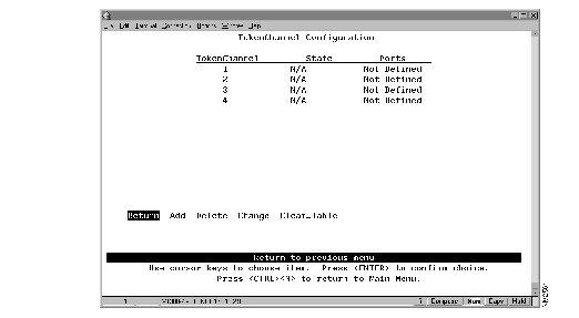
The following information is displayed on this panel:
- TokenChannel--The identifier of the TokenChannel (1 through 4).
- State--Indicates whether the TokenChannel is Up or Down. If the TokenChannel is not defined, the state is not applicable (N/A).
- Ports--Indicates which ports are assigned to this TokenChannel.
You must define the TokenChannels for both connected Catalyst 2600s before physically connecting the linked ports. Therefore, make sure that you have either disabled the ports or disconnected the cables before you configure the TokenChannel. Otherwise, you will create loops.
Note When you physically connect the linked ports, make sure that the ports with the lowest port numbers are connected together. For example, if a TokenChannel links ports 3, 6, and 7 of one Catalyst 2600 and ports 2, 4, and 5 of another Catalyst 2600, the ports must be connected to each other in the following manner: port 3 to port 2, port 6 to port 4, and port 7 to port 5.
| To
| Select
| Then
|
|---|
| Define a new TokenChannel...
| Add
| Specify the ports that compose the new TokenChannel. The port numbers must be entered from lowest to highest, separated by spaces.
|
| Change the definition of a TokenChannel...
| Change
| Specify the identifier of the TokenChannel to be changed and enter the new information. The ports associated with a TokenChannel must be disabled or disconnected before you change the TokenChannel definition.
|
| Delete the definition for a TokenChannel...
| Delete
| Specify the identifier of the TokenChannel to be deleted.
|
| Delete all TokenChannel definitions...
| Clear_Table
| Confirm the deletion of all TokenChannel definitions.
|
| Save your changes...
| Return
|
|
To ensure that the address tables (per port and master) are kept to a minimum size, you can configure an aging limit. The aging limit is used to determine when inactive MAC addresses are removed from the address table. To define address table aging limits, select Address Aging from the Configuration Menu. The Address Aging panel (Figure 5-10) is displayed.
Figure 5-10: Address Aging Panel
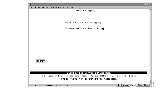
Note To completely disable address aging, you must disable address aging for the ports and the master address table.
To define the address aging limits of each port, select Port Address Table Aging on the Address Aging panel. The Port Address Table Aging panel (Figure 5-11) is displayed.
Figure 5-11: Port Address Table Aging Panel
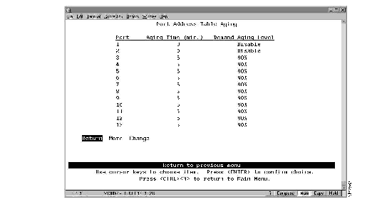
The following information is displayed on this panel:
- Port--The port identifier.
- Aging Time--The time (in minutes) an inactive MAC address will remain in the port's address table. Possible values are 0 through 9999 minutes. The default is 5 minutes. 0 indicates that address aging is disabled.
- Demand Aging Level--The capacity level (expressed as a percentage of the total capacity) the address table is allowed to reach before inactive addresses will be removed.When the threshold is reached, the addresses are cleared based on a random algorithm that is weighted to clear remote addresses first. Possible values are 50, 60, 70, 80, 90 percent, and Disable. The default is 90 percent.
|
To
| Select
| Then
|
|---|
| Change the aging time limit and the address table aging level...
| Change
| Specify the port, the new aging time, and the new aging level.
|
| Disable address removal for a port based on address age...
| Change
| Specify an Aging Time of 0.
|
| Disable address removal for a port based on address table capacity...
| Change
| Specify a Demand Aging Level of Disable.
|
| Save your changes...
| Return
|
|
To define the address aging limits of the master address table, select Master Address Table Aging on the Address Aging panel. The Master Address Table Aging panel (Figure 5-12) is displayed.
Figure 5-12: Master Address Table Aging Panel
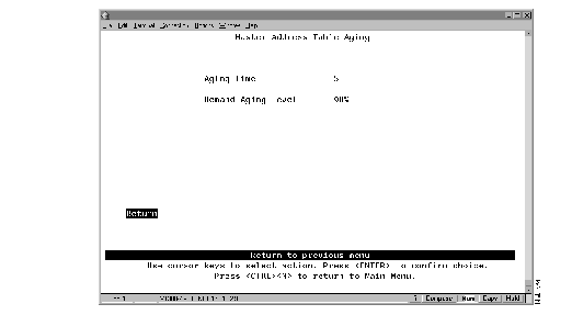
The following information is displayed on this panel:
- Master Address Table Aging Time--The time (in minutes) an inactive MAC address will remain in the master address table. Possible values are 0 through 9999 minutes. The default is 5 minutes. A value of 0 will disable the removal of addresses based on age.
- Demand Aging Level--The capacity level (expressed as a percentage of the total capacity) the master address table is allowed to reach before inactive addresses will be removed.When the threshold is reached, the addresses are cleared based on a random algorithm that is weighted to clear remote addresses first. Possible values are 50, 60, 70, 80, 90 percent, and Disable. The default is 90 percent.
|
To
| Select
| Then
|
|---|
| Change the aging time limit or the address table aging level...
| The appropriate parameter
| Specify the new value.
|
| Disable address removal based on address age...
| Aging Time
| Specify 0.
|
| Disable address removal based on address table aging level...
| Demand Aging Level
| Specify Disable.
|
| Save your changes...
| Return
|
|
To define the thresholds used to invoke alternative operating modes, select Switching Mode Threshold on the Configuration Menu. The Switching Mode Threshold panel (Figure 5-13) is displayed.
Figure 5-13: Switching Mode Threshold Panel
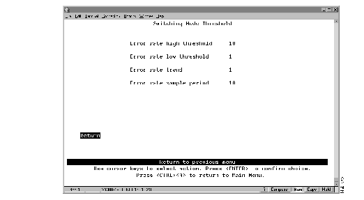
The following information is displayed on this panel:
- Error rate high threshold--When the port is set to adaptive mode, the error rate high threshold is one of the two criteria used to automatically force the port from cut-through mode to store-and-forward mode. If the percentage of CRC errors detected in a sampling period (the error rate trend) exceeds the error rate high threshold, the port is forced to operate in store-and-forward mode. Valid values are 0 through 100 percent. The default is 10 percent.
- Error rate low threshold--When the port is set to adaptive mode, the error rate low threshold is one of the two criteria used to automatically return the port to cut-through mode. If the percentage of CRC errors detected in a sampling period (the error rate trend) falls below the error rate low threshold, the port is returned to cut-through mode. Valid values are 0 through 100 percent. The default is 1 percent.
- Error rate trend--When the port is set to adaptive mode, the error rate trend is one of the two criteria used to automatically change the port operation from one mode to another. The error rate trend is the difference in number of CRC errors occurring between two successive sampling periods expressed as a percentage. The error rate trend is compared to the error rate high and low thresholds.
- If the percentage of errors detected in a sampling period exceeds the high threshold, the port is forced to operate in store-and-forward mode.
- If the percentage of errors detected in a sampling period falls below the low threshold, the port is returned to cut-through mode.
- The error rate trend algorithm is only active when the error rate is between the error rate low threshold and the error rate high threshold. Valid values are 0 through 100 percent. The default is 1 percent.
- Error rate sample period--The sample period (in minutes). Possible values are 1 to 120 minutes. The default is 10 minutes.
|
To
| Select
| Then
|
|---|
| Change any of the parameters...
| The appropriate parameter...
| Specify the new value.
|
| Save your changes...
| Return
|
|
All ports within a domain have the same LAN segment number, which can be learned (the default) or configured. When the Catalyst 2600 receives a source-routed explorer frame from a source-route bridge, it examines the frame and learns the local LAN segment number. Once learned, the Catalyst 2600 does not automatically process any changes to the local LAN segment number. Therefore, if you change the LAN segment number, you must clear the current LAN segment number before the new number can be learned.
To clear the current LAN segment number or manually configure a LAN segment number, select Source Route Configuration on the Configuration Menu. The Source Route Configuration panel (Figure 5-14) is displayed.
Figure 5-14: Source Route Configuration Panel
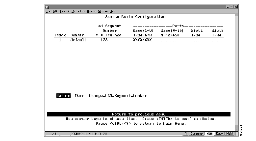
The following information is displayed on this panel:
- Index--The identifier of the source-route entry.
- Domain--The domain name.
- LAN Segment Number--The LAN segment number, or ring number in hexadecimal. An asterisk beside the number indicates that the ID was learned by the Catalyst 2600. The default is "unknown."
- Base and Slots--The ports of the switch (Base) or a Universal Feature Card (Slot) that belong to this domain.
|
To
| Select
| Then
|
|---|
| Manually assign a LAN segment number...
| Change_LAN_Segment_Number
| Specify the index number of the entry (if more than one entry exists) and specify the LAN segment number.
|
| Clear the current LAN segment number (to enable re-learning)...
| Change_LAN_Segment_Number
| Specify the index number of the entry (if more than one entry exists) and specify a null LAN segment number.
|
| Save your changes...
| Return
|
|


