|
|

Designed for use with the EtherSwitch 1420 Ethernet switch, the EtherSwitch 1420 modules consist of three Fiber Distributed Data Interface (FDDI) modules that support both fiber-optic and Category 5 unshielded twisted pair (UTP) cabling and four 100BaseT modules that support the 100BaseTX and 100BaseFX physical media specifications.
Without interrupting the network, these hot-swappable modules plug directly into the EtherSwitch 1420 high-speed expansion slots. The EtherSwitch 1420 then automatically configures the module to the network and verifies its operation.
CiscoPro product documentation and additional literature are available on a CD called Cisco Connection Documentation, CiscoPro Solutions. The CD is updated and shipped monthly, so it might be more current than printed documentation. To order the Cisco Connection Documentation, CiscoPro Solutions CD in North America, contact your local reseller; international customers, contact your local Cisco sales office. The CD is available both as a single CD and as an annual subscription. You can also access CiscoPro product documentation on the World Wide Web URL http://www.cisco.com.
Before going any further, make sure that the following items have been included with this package. If anything is missing, contact your Cisco customer service representative.
All network connectors and LEDs are on the FDDI module front panels. These panels are shown in Figure 1-1 and described in the following sections.
The FDDI Fiber DAS module is a dual-attach station (DAS) compatible with the ANSI X3T12 standard. It has two MIC connectors and uses 50/125- or 62.5/125-micron multimode fiber-optic cabling. It also has a 6-pin mini-DIN connector to connect to an optical bypass switch.
The FDDI Fiber SAS module is a single-attach station (SAS) compatible with the ANSI X3T12 standard. It has one MIC connector and uses 50/125- or 62.5/125-micron multimode fiber-optic cabling.
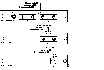
The FDDI UTP SAS module is a single-attach station (SAS) compatible with the ANSI X3T12 standard. It has an RJ-45 connector and uses two-pair Category 5 UTP cabling.
The following LEDs on the front panel indicate a module's operating status:
The LEDs also indicate the type of failure when the module does not pass the power-on self-test (POST). See Table 2-1 in the "Installation" chapter for more information.
The four 100BaseT modules support the 100BaseTX or 100BaseFX physical layer specifications. All network connectors and LEDs are located on the module front panel, as shown in Figure 1-2.
The 100BaseT modules are available in 100BaseTX and 100BaseFX configurations, supporting both switched and shared 100-Mbps operation.
The single-switched 100BaseT ports provide a dedicated 100 Mbps of bandwidth for direct connection to a single server, workstation, or another EtherSwitch 1420. The shared 100BaseT ports connect to the same types of devices as the switched 100BaseT ports but share 100 Mbps of bandwidth across all the ports.
The 100BaseTX modules are compatible with the 100BaseT IEEE 802.3u standard. They have RJ-45 connectors and use two-pair Category 5 UTP cabling. The following port configurations are available:
The 100BaseFX modules are compatible with the 100BaseT IEEE 802.3u standard. They have ST connectors and use 50/125- or 62.5/125-micron multimode fiber-optic cabling. The following port configurations are available:
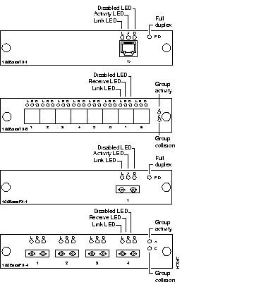
All of the 100BaseT modules have individual port LEDs. The shared 100BaseT modules have two group-status LEDs, and the switched 100BaseT modules have a full-duplex LED. The LEDs, shown in Figure 1-2, are described in the following list:
|
|