|
|

This chapter describes how to install and remove the EtherSwitch 1420 modules and how to use the module LEDs to interpret the results of the module power-on self-test (POST).
When unpacking the EtherSwitch 1420 modules, check the contents of the package against the list in "Packing List" in the "Introduction" chapter.
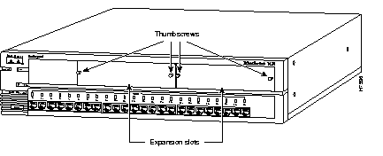
Blank faceplates on the EtherSwitch 1420 cover the high-speed expansion slots, as shown in Figure 2-1.

To remove a faceplate, follow these steps:
Step 1 Loosen the thumbscrews attaching the faceplate to the EtherSwitch 1420.
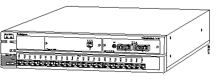
Step 2 Remove the faceplate from the EtherSwitch 1420 and store it for future use. Figure 2-2 shows an EtherSwitch 1420 with an empty expansion slot.

After the faceplate has been removed, follow these steps to install a module in an empty EtherSwitch 1420 high-speed expansion slot:
 | Warning Class 1 laser product. |
 | Warning Avoid exposure to the laser beam. |
Step 1 Slide the module into the slot card-guides until you feel the card touch the back of the unit.
Step 2 Push the module firmly until you feel it snap into place. Tighten the thumbscrews on the module faceplate.
When the module is installed correctly, its faceplate is flush with the front of the EtherSwitch 1420 unit.
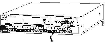
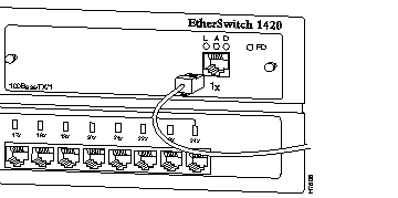
Step 3 Attach the cable. If you are attaching a fiber-optic cable, remove the rubber plugs from the fiber-optic port on the module and store the plugs for future use.
Attach the cable for a specific module as follows:


Figure 2-5 shows an EtherSwitch 1420 with two FDDI modules installed.

To remove a module from an EtherSwitch 1420 slot, follow these steps:
Step 1 Disconnect the cable from the module port.
Step 2 Loosen the thumbscrews attaching the module faceplate to the EtherSwitch 1420.
Step 3 Remove the module by grasping the thumbscrews and pulling the module out of the slot.
Step 4 Replace the blank faceplate to cover the empty expansion slot if you are not replacing the module with another.
When an FDDI module is installed in an EtherSwitch 1420, all LEDs on the module front panel are green, and the module automatically begins its POST. If the module passes the POST, the expansion slot LED (A or B) on the EtherSwitch 1420 remains green. If the module fails the POST, the expansion slot LED turns amber. A blinking expansion slot LED means a module is running its POST.
If an FDDI module fails the POST, the LEDs on the module indicate the type of failure. Table 2-1 shows how to interpret LEDs for POST failures.
For more information about the A and B expansion slot LEDs, refer to the NetBeyond EtherSwitch 1420 and EtherSwitch 1220 Installation and Configuration Guide.
| Failed Component | Connected LED | Activity LED | Disabled LED | Response |
|---|---|---|---|---|
| CPU | On | On | On | Call for assistance. |
| FLASH | On | On | On | |
| Local RAM | On | On | On | |
| Shared RAM | Slow blink | On | Slow blink | Start the management console and check for errors. |
| 100-Mbps controller | Slow blink | Slow blink | On | |
| FDDI controller | Slow blink | On | On | |
| ES loopback test | Fast blink | Slow blink | On | |
| FDDI loopback test | Fast blink | On | On | |
| Player+ (A) | On | On | Fast blink | |
| Player+ (B) | On | Fast blink | On |
When first powered on, all LEDs on the module front panel are green, and a POST automatically begins. If the module passes the POST, the expansion slot LED (A or B) on the EtherSwitch 1420 remains green. If the module fails the POST, the expansion slot LED turns amber.
For a complete description of each LED, see "100BaseT Module LEDs" in the chapter "Introduction."
|
|