|
|

Table Of Contents
Duplicated Communication Paths
Synchronization and State Transfer
Fault Tolerance
Intelligent Contact Management (ICM) software is a fault tolerant call routing system that continues to operate without interruption in the case of hardware, software, or communications failures. The main goals of the ICM's fault tolerant architecture are to:
•
Minimize time periods during which the system is non-responsive to call routing requests (for example, while the system is being reconfigured due to a component failure or recovery).
•
•
The ICM's fault tolerant mechanisms operate in the background and are not visible from within ICM applications. However, it is still important that you have a general understanding of the fault tolerant architecture and the implications it has for system administration.
In some cases, the level of fault tolerance in the ICM system can affect which administration tasks you need to perform. For example, in duplexed database configurations many typical database administration tasks such as database backups become unnecessary because exact copies of the central database are kept on each side of the system on separate computers.
This chapter provides an overview of ICM fault tolerance with a special emphasis on the fault tolerance of the Central Controller and the central database.
Architecture
The architecture of ICM software allows the system to continue to function if one component fails. This ability is called fault tolerance. To ensure that ICM software continues to operate in the case of a computer failure, all critical parts of the system can be physically duplicated. There can be two or more physical Network Interface Controllers (NICs), two physical Peripheral Gateways (PGs) at each call center, and two Central Controllers. The communication paths between critical components can also be duplicated.
The critical components of ICM software include the Central Controller (CallRouter and Logger), PGs, and NICs. Normal Admin Workstations (AWs) are not considered to be critical to the operation of the system since they play no active role in routing calls or storing historical data.
When both instances of a component are available to the system, that component is said to be duplexed; when only one of the pair is available, the component is running simplexed. You might have some components in your ICM system that are duplexed and others that are simplexed. For example, you might have a duplexed Central Controller (two CallRouters and two Loggers) and simplexed Peripheral Gateways at call center sites.
It takes more than duplicate hardware to achieve fault tolerance. The ICM system can quickly detect that a component has failed, bypass that component, and use its duplicate instead. ICM software can also initiate diagnostics and service so that the failed component can be fixed or replaced and the system returned to duplexed operation.
Approaches to Fault Tolerance
ICM software uses two approaches to fault tolerance: hot standby and synchronized execution. In the hot standby approach, one set of processes is called the primary, and the other is called the backup. In this model, the primary process performs the work at hand while the backup process is idle. In the event of a primary process failure, the backup process is activated and takes over. Peripheral Gateways optionally use the hot standby approach to fault tolerance.
ICM software uses synchronized execution in the Central Controller. In the synchronized execution approach, all critical processes (CallRouter, Logger, and Database Manager) are duplicated on separate computers. There is no concept of primary or backup. Both process sets run in a synchronized fashion, processing duplicate input and producing duplicate output. Each synchronized system is an equal peer. Each set of peers is a synchronized process pair.
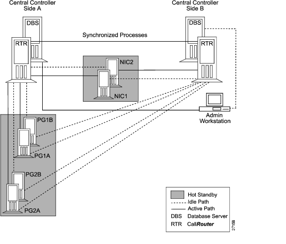
In the event that one of the synchronized processes fails (for example, a CallRouter goes off-line), its peer continues to run. There is no loss of data and call continue to be routed. When the failed member of the pair returns to operation, it is resynchronized with its peer and begins to run again as a synchronized process. Figure 2-1 shows how synchronized execution and hot standby are applied in ICM software.
Figure 2-1 Duplexed ICM Fault Tolerance
PGs and NICs use the hot standby approach to fault tolerance. Note that the duplexed NIC in Figure 2-1 is implemented on two separate computers. Each computer has active and idle connections to the sides of the Central Controller. NIC fault tolerance is described in more detail later in this chapter.
Duplicated Communication Paths
Each NIC, Peripheral Gateway, and Admin Workstation has two communication paths to the Central Controller (see Figure 2-1). The two paths connect the device (for example, a PG) to a Central Controller Agent process on each side of the Central Controller. The Central Controller Agent is a software process that manages communications between the Central Controller and nodes in the ICM system.
At any one time, one of the two communications paths is active and the other is idle. All communication traffic between the Central Controller and the device is sent on the active path. If the active path fails for any reason, the second path is activated and all traffic is switched to the newly active path. The previously active path becomes the idle path.
The communication protocols use buffering and acknowledgments to ensure that no messages are lost during the path failure and switch-over. After a communication path failure, the device periodically attempts to re-establish communication along the failed path.
A different mechanism is used for the real-time data feed to Admin Workstations. See Figure 2-8, later in this chapter, for more information.
Node Manager
Each ICM component (except the client-only Admin Workstation) includes a Node Manager process. The Node Manager is in charge of restarting Intelligent Contact Management processes that have failed.
For example, each Logger and each CallRouter has its own Node Manager. If a Logger and CallRouter are installed on the same machine, two separate Node Managers run on that machine. If Loggers for multiple customers run on a single machine, a separate Node Manager runs for each customer.
When a failure occurs in a single-customer ICM system, the Node Manager may shut down the machine to initiate a reboot. However, in a network service provider (NSP) environment when a Logger or CallRouter fails, components for other customers might still be active on the machine. Therefore, the Node Manager for an NSP component does not shut down and reboot the machine. Manual intervention may be required to restore the failed component.
If the Node Manager does initiate a reboot, the Node Manager itself restarts when the machine reboots. The Node Manager then starts the other processes for the component. On a Distributor Admin Workstation, you can choose whether to have the Node Manager automatically restart when the computer reboots.
For more information on Node Manager start-up options, see the Cisco ICM Software Installation Guide.
Central Controller
The Central Controller includes the CallRouter, Logger, and the Database Manager. The CallRouter and Logger processes are typically on separate computers. However, in smaller call center configurations the CallRouter and Logger processes can be on the same computer. The Database Manager works very closely with the Logger. The Logger and Database Manager processes are always on the same computer.
A duplexed Central Controller uses the synchronized execution approach to fault tolerance. The Central Controller processes are duplicated and run as synchronized process pairs. In synchronized execution, if one component fails its peer continues running and the system runs without interruption. The Database Manager is also duplicated, but technically it does not run synchronized. Since all modifications to the database come through the Logger, the databases automatically remain synchronized.
Two Sides
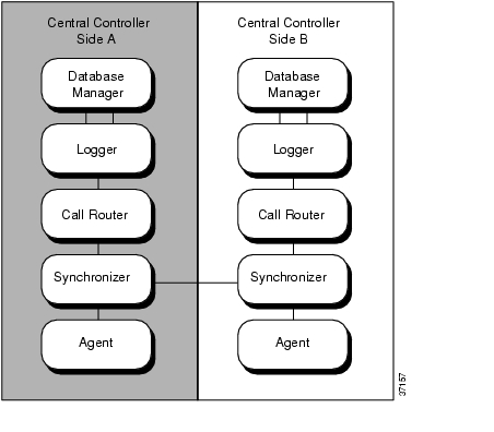
All components of the Central Controller, with their duplicates, form one logical duplexed system. The system can be divided into two sides, each of which contains one instance of a component. Each side of the Central Controller has a Database Manager, Logger, CallRouter, Synchronizer, and an Agent. By convention, the two sides are referred to as Side A and Side B.
All components within a side are collocated; that is, located on the same local area network (LAN). However, Side A might be geographically separated from Side B. Figure 2-2 shows the two sides of a duplexed Central Controller.
Figure 2-2 Duplexed Central Controller
During normal operation, the two sides run in parallel. For example, information about each incoming call is processed by both CallRouters. Both CallRouters, using the same call routing scripts and identical information about the call centers, determine the same destination for the call. Both sides of the Central Controller receive the same information from the Peripheral Gateways and Admin Workstations.
A duplexed Central Controller can tolerate a single device or system failure (for example, the loss of one CallRouter) without losing functions. A double failure, while extremely rare, typically results in some loss of functions. An example of a double failure would be if both Loggers in a duplexed system were to go off-line.
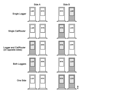
Single failures are typically caused by system crashes, operating system failures, or disk failures. However, LAN outages and IP router failures can also cause single failures. Figure 2-3 shows five possible Central Controller failure scenarios.
Figure 2-3 Central Controller Failure Scenarios
Each of these failures affects system functions differently:
•
•
•
•
•
A double CallRouter failure would temporarily disrupt call routing and reporting functions. This type of failure is extremely rare (especially in geographically distributed Central Controller configurations).
Geographic Distribution
To provide maximum protection against disasters such as fires, floods, and earthquakes, the two sides of the Central Controller can be in separate locations—even in separate cities. The two Synchronizers communicate with each other via a private wide area network (WAN) to ensure that they remain synchronized. This WAN, called the private WAN, is used for no other purpose than to ensure synchronization between the sides of the Central Controller.
For details on collocated and distributed Central Controller configurations, see the Cisco ICM Software Installation Guide.
Role of the Synchronizers
The Synchronizers play the key role in maintaining synchronized execution across the two sides of the Central Controller. All input for the CallRouter and any changes to the Logger must pass through the Synchronizers.
Each time a Synchronizer receives input, it passes that input to its duplicate on the other side. The two Synchronizers cooperate to ensure that they are both sending the same input to the Central Controllers on both sides of the system.
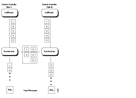
Figure 2-4 shows how the Synchronizers combine input messages and send the messages in the same order to each side of the Central Controller.
Figure 2-4 Role of the Synchronizers
Both CallRouters receive the same input and generate the same output. The Synchronizers ensure that both sides of the Central Controller return identical destinations for the same call and write identical data to the databases.
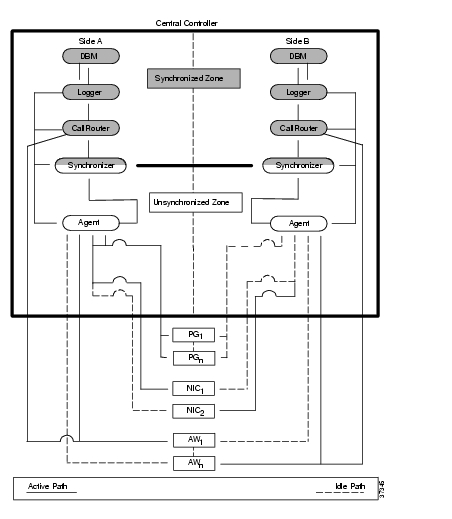
Figure 2-5 further illustrates the Central Controller and its device connections. In the case of DOS-based NICs, each physical NIC is located with one side of the Central Controller.
Figure 2-5 ICM Fault-Tolerant Architecture
Each PG, NIC, and Admin Workstation has duplicate communication paths to the Central Controller. If there is a failure on one side of the Central Controller, the PGs, NICs, and Admin Workstations can switch their communication paths to the active side of the Central Controller. As shown in Figure 2-5, only one communication path is active at a time. The other communication path is idle (indicated by a dotted line). ICM software sends heartbeats (brief periodic messages) over the idle path to ensure that it can still be used in the event that the active path fails.
Synchronization and State Transfer
In synchronized execution, duplicated processes are always processing identical input and generating identical output. If one process fails, the other continues to operate without interrupting system operation. Once the failed process returns, it is immediately updated with the current state of ICM processes running on its peer.
In order to synchronize one peer with another after a failure, the system performs a state transfer. The state transfer facility allows a synchronized process (for example, a CallRouter) to copy the variables in its memory to its peer. The recovering system receives the variables from the currently executing system and is able to restart with a copy of the current state of ICM processes. For example, as soon as a failure is detected on the Side A CallRouter, ICM software uses only Side B. When the Side A CallRouter is restarted, ICM software invokes a state transfer to immediately update the Central Controller Side A components with the current state of their counterparts on Side B.
In order to better understand synchronization and state transfer, it might help to take a closer look at CallRouter and Logger recovery.
CallRouter Recovery
When a single CallRouter process fails for any reason, ICM software continues to operate without any loss of functions by using the other side of the Central Controller. All attached devices (PGs, NICs, and Admin Workstations) switch their active communications paths to the remaining side. This ensures that devices such as PGs continue to receive CallRouter output through the active CallRouter on the other side of the system.
As a consequence of the CallRouter failure, the entire side of the Central Controller is removed from service. The Logger and Database Manager associated with the failed CallRouter see no further inputs (and will not until the failed CallRouter is restored to full operation). All components on the failed side of the Central Controller lose synchronization with the other side. The CallRouter, Logger, and Database Manager must all be resynchronized before normal duplexed operation can resume.
For a single-customer ICM, the recovery process begins when the Node Manager notices the failure of the CallRouter and automatically restarts it. In a network service provider (NSP) environment where several ICM instances may be running on the same machine, the Node Manager cannot restart the machine. In NSP environments manual intervention may be required to restart the failed CallRouter.
The restarted CallRouter immediately initiates a state transfer from its currently executing peer. Each CallRouter sends a message to its Logger. The Loggers then perform their own state transfer.
When the state transfer is complete, all processes are now synchronized. The newly on-line Central Controller sends an in-service status to all local Agents. It then begins processing input messages. After the state transfer, both sides of the Central Controller see exactly the same sequence of input messages. At this point the ICM system is returned to full duplexed operation.
Logger and Database Manager Recovery
Logger recovery is closely linked with central database recovery. In central database recovery, the SQL Server component of the central database is accessed directly through its client interface rather than through proprietary ICM interfaces. Therefore, in addition to synchronization and state transfer, the following database recovery procedures must be performed before the Logger can return to full duplexed operation:
•
•
•
When a single Logger process fails, ICM software continues to operate with the Logger on the other side. The remaining Logger ensures that output messages continue to reach PGs and Admin Workstations. The ICM's Message Delivery Service detects the failure of the Logger and notifies the PGs and Admin Workstations, which switch their active communication paths to the on-line Logger. At this point, both CallRouters are in service, but only one Logger is available.
For a single-customer ICM, when the Node Manager detects that the Logger has gone off-line it initiates a shutdown and reboot of the machine. In an NSP environment, the Node Manager does not restart the machine. In this case, manual intervention may be needed to restart the failed Logger.
The Logger's Node Manager automatically restarts when the machine reboots. Next, the SQL Server service starts automatically as part of the reboot. SQL Server automatic recovery runs to ensure that the returning database is consistent and that all transactions committed before the failure are recorded on disk. Once automatic recovery is complete, the Logger can then go through the application synchronization and state transfer process. If configuration data in the on-line database has changed, the state transfer also updates the configuration data in the returning database. However, in most cases configuration data will not have changed during the failure.
Once the two Loggers are returned to synchronized execution, ICM software may need to recover historical data that was accumulated during the off-line period. This process, referred to as Recovery, is described in the next section, "Fault Tolerance".
In a double Logger failure (both Loggers are off-line), the CallRouter continues to route calls. This is possible because the CallRouter loads configuration data in its program memory at system initialization. In a double Logger failure scenario, all messages and data that the CallRouter sends to an off-line Logger are discarded until the Logger is completely recovered.
Database Fault Tolerance
The Central Controller database provides two major ICM functions:
•
•
Each time a CallRouter starts, it loads configuration data from the central database into its program memory. Once the configuration data is loaded, the CallRouter can begin to route calls (even when the central database is not available). Therefore, when a CallRouter fails an d restarts, at least one Logger and central database must be available so that the CallRouter can load the configuration data into memory.
In addition to configuration data, Peripheral Gateways, NICs, and the CallRouter itself all produce historical data. The system components gather historical data and pass it to the CallRouter, which then delivers it to the Logger and the central database. If the system uses the Historical Data Server (HDS) facility, the Logger passes the historical data on to an Admin Workstation.
The ability of the CallRouter to deliver data to the Logger and the central database is not necessary for call routing. However, the ICM's monitoring and reporting facilities require both real-time data and historical data from the central database. Database fault tolerance and data recovery, therefore, are extremely important to the reporting functions of ICM software.
ICM Database Recovery
Database recovery is the process of bringing an off-line database up to the same state as an on-line database. In a database device failure, (for example, in a disk failure), some manual intervention is required to restore duplexed operation and bring the off-line database up to date. The following scenarios describe what happens in a system failure, a disk failure, and a software failure.
System Failure
When a single Logger, CallRouter, or Database Manager fails (for example, due to a power outage), the associated central database will go off-line. The process of bringing the off-line database back to full synchronization is completely automatic. If the Logger machine reboots, SQL Server automatic recovery runs to ensure that the database is consistent and that all transactions committed before the failure are recorded on disk.
Note
After SQL Server automatic recovery is complete, the off-line Logger synchronizes its state with the state of the on-line Logger. After the state transfer process takes place, both members of the Logger pair can execute as a synchronized process pair.
During the time that one database is off-line, configuration data may have been added to the contents of the on-line database. If any configuration data changed while one database was off-line, the configuration changes are applied to the database as part of the Logger's state transfer process. This configuration update happens as part of the state transfer before synchronized execution begins.
Any historical data that accumulated in the on-line database is recovered after synchronized execution begins. Rather than attempting to recover the historical data immediately, ICM software first restores system fault tolerance (that is, duplexed database capability and synchronized execution).
ICM software recovers historical data from the on-line database using a special process called Recovery. In Recovery, the Logger communicates with its counterpart on the other side of the Central Controller and requests any historical data that was inserted during the off-line period. The counterpart delivers the data over the private network that connects both sides of a duplexed Central Controller.
Disk Failure
A disk failure requires additional steps. If a disk failure disables one side of the Central Controller database, the disk must be repaired or replaced.
Note
Customer Support will repair or replace the disk and perform the following steps:
Step 1
Step 2
•
•
•
At the time of the state transfer, any missing configuration data will be restored. Historical data is restored by the Recovery process, which is run automatically each time the Node Manager process starts on the Logger, or by loading the data from a backup tape.
Software Failure
Cases of software failure that leave a Central Controller database unavailable are handled in the same way as a disk failure (if the failure cannot be repaired by existing software tools). Contact the Cisco Technical Assistance Center (TAC) if such a failure occurs.
Network Interface Controllers
The NIC has four physical controllers on each side of the Central Controller. Each of these controllers can simultaneously handle calls from the signaling network. Typically, each physical NIC handles part of the total call routing load for ICM software.
The NIC processes are implemented as non-synchronized process pairs (one process on each side of the Central Controller). In some cases, NICs reside on their own hardware platforms. For example, the AT&T and BT NICs require a separate DOS platform. In all other cases, the NIC runs as a process on the CallRouter machine.
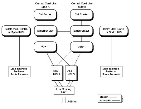
As a non-synchronized process pair, the NICs operate without knowledge of each other. They are managed by the Node Manager and communicate with other CallRouter processes via the Message Delivery Service (MDS). Figure 2-6 shows how fault tolerance is implemented for various NICs.
Figure 2-6 NIC Fault Tolerance
As an alternative, an INAP NIC might be used. The INAP NIC uses the Intelligent Network Application Protocol (INAP) to communicate with the signaling network. The INAP NIC runs as a process on the CallRouter machine. The INAP NIC communicates with an INAP Gateway, which is a DOS-based process that communicates directly with the signaling network. For greater capacity, a single INAP NIC may connect to multiple INAP Gateways.
In a duplexed environment, two NICs are on-line and handling routing requests simultaneously. Typically, each NIC handles part of the total call routing load for ICM software. The Synchronizers combine the two input streams to ensure that both sides of the Central Controller receive the same routing requests. If one of the NIC processes fails, or one side of the Central Controller is removed from service, the signaling network detects that communication is no longer possible to that NIC and automatically sends all routing requests to the remaining NIC process.
Peripheral Gateways
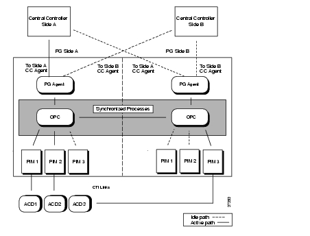
Peripheral Gateways use a combination of the synchronization and hot standby approaches to fault tolerance. The Open Peripheral Controller (OPC) operates as a synchronized process pair on a duplexed PG system. The Peripheral Interface Managers (PIMs) typically use the hot standby approach. Figure 2-7 shows how synchronization and hot standby are employed in a duplexed Peripheral Gateway (PG).
Figure 2-7 PG Fault Tolerance
The OPC processes communicate with each other via a private network connection and the Message Delivery Service (MDS). The MDS provides a synchronizer service which combines the input streams from the PIMs and PG Agents on both sides of the PG to ensure that both OPC processes see exactly the same input.
The OPC process is responsible for activating PIMs and PG Agents on each side of the duplexed PG. The OPC process also supplies uniform message sets from various PG types to the Central Controller.
The PIMs manage the interface between different types of ACDs and the OPC. PIMs are duplicated on each side of the system and operate in hot standby mode. A PIM can be active on either side of the duplexed PG, but not on both sides at the same time. For example, in Figure 2-7 PIMs 1 and 2 are active on Side A; PIM 3 is active on Side B. The duplexed OPCs communicate with each other through the MDS to ensure that a PIM is active only on one side at a time.
The duplexed PG architecture protects against a failure on one side of the PG. For example, if an adapter card controlling access to an ACD fails a hot standby PIM can use the alternate PIM activation path. As shown in Figure 2-7, PIM3 has been activated from Side B of the PG. This might be in response to an adapter failure between the Side A PIM3 and ACD3. In this type of failure scenario, the PG is able to maintain communication with the attached ACD.
Only one PG Agent actively communicates with a side of the Central Controller. When messages arrive at the Central Controller, they are delivered to both sides by the Central Controller Synchronizer process. The PG maintains idle communication paths to both sides of the Central Controller in case a switch-over to the other side of the Central Controller or PG is necessary.
Real-Time Distributors
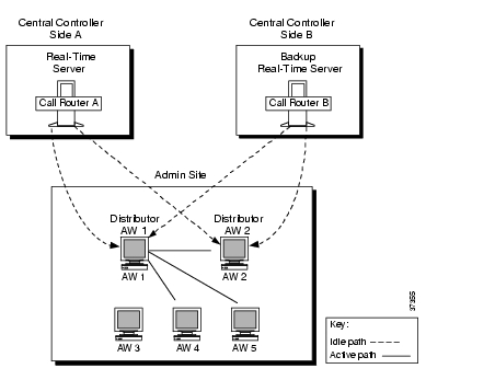
To allow users to monitor current call center activity, ICM software must send up-to-date data to the Distributor Admin Workstation in a reliable and timely manner. The real-time data arrives at the Central Controller from the Peripheral Gateways, which are monitoring activity at each call center. The CallRouter acts as the real-time server. The CallRouter for the other side of the Central Controller is the back-up real-time server.
Figure 2-8 illustrates the real-time architecture of the ICM system.
Figure 2-8 Real-Time Architecture
Admin Workstations can be located with one or both sides of the Central Controller, at a call center, or at another site. Any site that contains AWs is referred to as an admin site.
The CallRouter is responsible for providing real-time data to a Distributor AW at each admin site. Each site has at least one, and usually two, Distributor AWs that serve as real-time data distributors for the site. The primary Distributor AW maintains an active connection to the real-time server through which it receives real-time data.
Client AWs at the site receive their real-time data through a connection to a Distributor AW. These AWs are called Client AWs because they do not have the local database and distributor processes required to receive real-time data directly from the Central Controller real-time server.
If the site has two Distributor AWs, Client AWs are configured to automatically switch to a secondary Distributor AW if the first distributor becomes non-functional for any reason. The secondary Distributor AW also maintains connections to the real-time server; however, these connections remain idle until needed.
You specify whether to install Distributor or Client AWs through the ICM Setup tool.
Historical Data Servers
In some environments, historical data is forwarded to the Distributor AW where they are stored in a special database. The distributor then acts as an Historical Data Server (HDS) for the admin site. Admin Workstations at the site query historical data from the HDS rather than directly from the Logger.
When the HDS feature is used, two Distributor AWs at a site are set up as HDS machines. Each has its own HDS database. The same fault-tolerant strategy that applies to the real-time Distributor AW also applies to the HDS. That is, when the primary HDS fails, other Admin Workstations at the site automatically switch over to use the backup HDS.
The "Historical Data Server" section in Chapter 4, "Database Administration" provides more information on setting up an HDS AW.
Simplexed Operation
If you have a simplexed Central Controller configuration, you are vulnerable to a single device failure (for example, a system failure, process failure, or a disk crash). You should have a strategy in place for keeping daily backups of the central database. Your backup strategy might involve regularly scheduled backups, mirrored disk configurations, or Redundant Array of Inexpensive Disk (RAID) configurations. You should always have the central database backed up on removable media.
If the central database becomes unavailable due to disk failure, contact Cisco Customer Support. A support representative can assist you in replacing the disk, rebuilding the database, and restoring the configuration and historical data.
For more information on database backup and restore procedures for simplexed Central Controllers, see Chapter 5, "General Administration."
![]()
![]()
![]()
![]()
![]()
![]()
![]()
![]()
Posted: Mon Dec 6 11:48:16 PST 2004
All contents are Copyright © 1992--2004 Cisco Systems, Inc. All rights reserved.
Important Notices and Privacy Statement.