|
|

Figure 3-1 details the tasks you should perform and the order they should be performed to get started with the 6400 SCM.
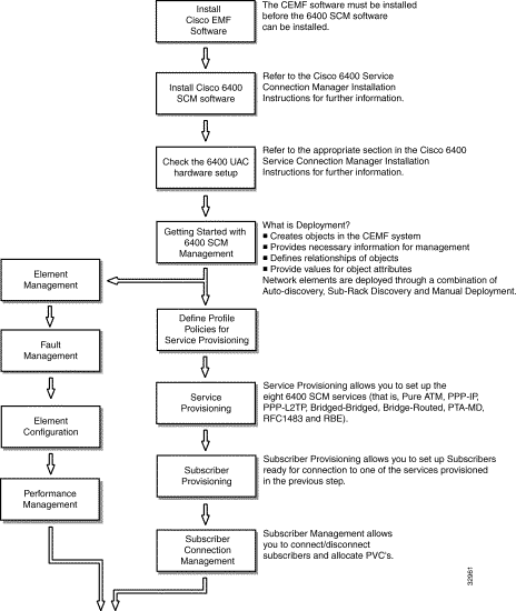
Refer to the CEMF Installation Instructions for further information.
Refer to the Cisco 6400 Service Connection Manager Installation Instructions for further information.
Before you can use the Cisco 6400 SCM to manage the Cisco 6400 UAC you have to carry out some base configuration changes, using IOS, which may need to be run on your Cisco 6400 UAC.
Refer to the appropriate section in the "Cisco 6400 Service Connection Manager Installation Guide" for further information.
Deployment informs the Cisco 6400 SCM of the presence of supported network elements.
The Cisco 6400 SCM objects can be deployed manually or automatically by launching a wizard-style deployment tool that enables you to automatically deploy a network modeled in CEMF. The deployment wizard deploys objects in CEMF in advance of actual deployment on a Cisco 6400 SCM in the field.
The Cisco 6400 SCM detects the presence of previously deployed network equipment as soon as that equipment becomes operational.
The Cisco 6400 SCM can auto-discover equipment as an alternative to manual deployment.
Deployment is one of the first stages of the provisioning process. Deployment is occasionally referred to as Provisioning. It is also referred to as Pre-Provisioning - meaning that part of the network hardware setup before the service is actually provisioned. Once objects are deployed, the initial state of all objects will be normal.
Pre-Provisioning is the process of reserving and configuring a space in the system for network equipment, which have not yet been physically slotted into the system rack. It refers to a particular state of the device or object. If an object/device is in pre-provisioned state, it means that though the device/object is not present, the system has been pre-provisioned to hold an object of similar type. Thus the line cards in the 6400 SCM can exist in a state known as pre-provisioned and the 6400 SCM does not monitor their status. When the cards are placed in the physical equipment, it is possible to change the line card from the pre-provisioned state to the commissioned state by clicking on the Commission button.
You can also create Site, Chassis, NPR, NSP and Line Card objects manually from the MapViewer or Object Manager applications. This is what we term Manual Deployment.
Producing a manageable 6400 UAC in CEMF is a two stage process, as shown in Figure 3-2.
The first stage is deployment at Chassis level. The Cisco 6400 Chassis could be manually deployed OR alternatively the Cisco 6400 Chassis could be Auto discovered. The second stage of the deployment process is to deploy the SCM objects at Sub-chassis level. This involves Auto discovering the sub chassis and/or deploying additional sub chassis objects manually.
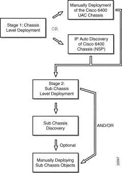
Table 3-1 lists the various objects that can be deployed and the objects from which they can be launched. For example, you could deploy a Chassis and NSP or a Site from a Manager object.
| Task | Launch Point | |||
|---|---|---|---|---|
| Manager | Site | Chassis | NSP | |
| Deploy a Site | Yes | Yes | No | No |
| Deploy a Chassis and associated NSP | Yes | Yes | No | No |
| Deploy an NRP | No | No | No | Yes |
| Deploy a Line Card | No | No | No | Yes |
A 6400 Chassis and NSP card must be deployed under a site.
Two node switch processor cards (NSPs) can be deployed in either or both of two dedicated slots (0A and 0B) in the middle of the Cisco 6400 chassis. One NSP is required for system operation, the second NSP provides fault tolerance.
To deploy a 6400 Chassis and NSP, proceed as follows:
Step 1 Place the cursor over a relevant object in the a network map, a relevant object in the object manager or by using an object pick list on an open element manager window, refer to the Table 3-1 for information to determine which objects you can deploy from.
Step 2 Click and hold down the right mouse button.
Step 3 Select the Deploy, Cisco 6400 UAC, Chassis and NSP option.
The Deployment Selector window appears.

Step 4 Click Forward.
Step 5 Enter the Number of chassis: you wish to deploy.
You can only deploy one chassis under a site.
Step 6 Click Forward.
Step 7 Enter the Chassis name.
Step 8 Click Forward.
Step 9 Enter an NSP Name, IP Address (for the primary NSP), SNMP Read Community, the SNMP Write Community and select an SNMP Version.
Step 10 Click Forward.
Step 11 Repeat steps 7 to 9 for the Number of chassis entered in step 5.
Step 12 The Deployment Summary details appear in the Deployment Summary Screen.
Step 13 Click Finish (if the Deployment Summary information is correct).
Step 14 Click Dismiss to complete the deployment and close the Deployment Summary Screen. This creates the relevant number of objects in CEMF.
Auto Discovery is used to discover an existing network and can save time and effort. The network is interrogated for IP and SNMP devices and an object created for each new device discovered.
Auto discovery is also used to identify new SCM chassis and specifically the NSP card within each chassis.
The Auto Discovery application has three mechanisms for discovering devices:
1. IP
ICMP pings are used to find devices in a given IP address range. This finds which IP device exists, but does not discover what kind of device it is.
2. SNMP
SNMP get requests are used to find devices in a given IP address range. Several SNMP community strings can be used so that equipment with different community strings can be discovered in the same discovery session. The SNMP information returned by devices is used to work out what kind of device has been found.
3. IP and SNMP
ICMP pings are used to find devices and then SNMP requests are used to interrogate the devices to find out what kind of device they are. This is the default mechanism.
Auto Discovery can discover devices on more than one subnetwork by using multi-hop discovery. It can be scheduled to run at preset times, the CEMF User Guide details how to set the schedules.
An option is available to specify the physical location that discovered objects will be created under.
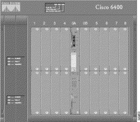
Once the 6400 UAC is detected, an object representing a Chassis is created and placed under the Site from which auto discovery was launched. A map of the chassis is also created, as shown above.
Commissioning an NSP within a chassis causes sub-chassis discovery to begin. This task discovers all line cards installed in the chassis of the NSP being commissioned.
Step 1 Select the Cisco 6400 UAC, Manage, NSP option from a relevant network map, a relevant object in the object manager or by using an object pick list on an open Element Manager window. Refer to Table 4-1 for information on which maps nodes or objects allow you to launch the Cisco 6400 NSP Management window.
Step 2 Click the Configuration tab.
Step 3 Click Commission.
The sub-chassis discovery task initiates and all cards that were not pre-provisioned are discovered and added. The NSP and all related cards are now in a commissioned state.
Step 1 Select the Cisco 6400 UAC, Manage, NSP option from a relevant network map, a relevant object in the object manager or by using an object pick list on an open Element Manager window. Refer to Table 4-1 for information on which maps nodes or objects allow you to launch the Cisco 6400 NSP Management window.
Step 2 Click the Configuration tab.
Step 3 Click Decommission.
The NSP and all related cards are now decommissioned.
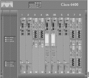
Node route processor cards (NRPs) can be installed in any one or all of the eight chassis numbered 1 to 8. Figure 1-2 shows three NRPs installed in chassis slots 1, 2, 5 and 6.
To deploy an NRP and Port, proceed as follows:
Step 1 Place the cursor over a relevant object in the a network map, a relevant object in the object manager or by using an object pick list on an open element manager window, refer to the Table 3-1 for information to determine which objects you can deploy from.
Step 2 Click and hold down the right mouse button.
Step 3 Select the Deploy, Cisco 6400 UAC, NRP and Port option.
The Deployment Selector window appears.

Step 4 Click Forward.
Step 5 Enter the Number of NRPs you wish to deploy.
Step 6 Click Forward.
Step 7 Enter a Slot Number, NRP Name, NRP IP Address, NRP SNMP Read Community, NRP SNMP Write Community and select an NRP SNMP Version in the NRP Details frame.
Step 8 Click Forward.
The Object Details Screen appears.
Step 9 Enter an NSP IP Address, NSP SNMP Read Community, NSP SNMP Write Community and an NSP SNMP Version in the Attributes frame.
Step 10 Click Forward.
Step 11 Repeat steps 7 to 10 for the Number of NRPs entered in step 5.
Step 12 The Deployment Summary details appear in the Deployment Summary Screen.
Step 13 Click Finish (if the Deployment Summary information is correct).
Step 14 Click Dismiss to complete the deployment and close the Deployment Summary Screen.
Half-height node line cards (NLCs) can be installed in any one or all of the eight slots numbered 1 to 8. One or two NLCs can be installed in each slot, for a maximum of 16 per chassis.
To deploy an OC3 Line Card and Ports, proceed as follows:
Step 1 Place the cursor over a relevant object in the a network map, a relevant object in the object manager or by using an object pick list on an open element manager window, refer to the Table 3-1 for information to determine which objects you can deploy from.
Step 2 Click and hold down the right mouse button.
Step 3 Select the Deploy, Cisco 6400 UAC, OC3 Line Card and Ports option.
The Deployment Selector window appears.
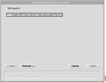
Step 4 Click Forward.
Step 5 Enter the Number of OC3 Line Cards you wish to deploy.
Step 6 Click Forward.
Step 7 Enter a Slot Number, Sub-Slot Number, OC3 Line Card Name, NSP IP Address, NSP SNMP Read Community, NSP SNMP Write Community and select an NSP SNMP Version in the Attributes frame.
Step 8 Click Forward.
Step 9 Repeat steps 6 to 8 for the Number of OC3 Line Cards entered in step 5.
Step 10 The Deployment Summary details appear in the Deployment Summary Screen.
Step 11 Click Finish (if the Deployment Summary information is correct).
Step 12 Click Dismiss to complete the deployment and close the Deployment Summary Screen.
Half-height node line cards (NLCs) can be installed in any one or all of the eight slots numbered 1 to 8. One or two NLCs can be installed in each slot, for a maximum of 16 per chassis.
To deploy an DS3 Line Card and Ports, proceed as follows:
Step 1 Place the cursor over a relevant object in the a network map, a relevant object in the object manager or by using an object pick list on an open element manager window, refer to the Table 3-1 for information to determine which objects you can deploy from.
Step 2 Click and hold down the right mouse button.
Step 3 Select the Deploy, Cisco 6400 UAC, DS3 Line Card and Ports option.
The Deployment Selector window appears.

Step 4 Click Forward.
Step 5 Enter the Number of DS3 Line Cards you wish to deploy.
Step 6 Click Forward.
Step 7 Enter a Slot Number, Sub-Slot Number, DS3 Line Card Name, NSP IP Address, NSP SNMP Read Community, NSP SNMP Write Community and select an NSP SNMP Version in the Attributes frame.
Step 8 Click Forward.
Step 9 Repeat steps 6 to 8 for the Number of DS3 Line Cards entered in step 5.
Step 10 The Deployment Summary details appear in the Deployment Summary Screen.
Step 11 Click Finish (if the Deployment Summary information is correct).
Step 12 Click Dismiss to complete the deployment and close the Deployment Summary Screen.
![]()
![]()
![]()
![]()
![]()
![]()
![]()
![]()
Posted: Mon Jan 31 22:32:18 PST 2000
Copyright 1989 - 2000©Cisco Systems Inc.