|
|

Table Of Contents
Initially Configuring the Cisco DSLAM
Methods for Configuring the DSLAM
Verifying Installed DSLAM Software and Hardware
Setting the Subtend Node Identifier
Using the ATM Default Addressing Scheme
Manually Setting the ATM Address
Modifying the Physical Layer Configuration of the Default ATM Interface
Configuring IP Interface Parameters
Testing the Ethernet Connection
Configuring Network Clock Priorities and Sources
Configuring the Transmit Clocking Source
Providing Clock Synchronization Services
Configuring the Network Routing
Configuring the Time, Date, and Month
Configuring Support for Both SNMPv1 and SNMPv2
Configuring Support for SNMPv2
Creating or Modifying an SNMP View Record
Creating or Modifying an SNMP Context Record
Creating or Modifying an SNMPv2 User Record
Creating an SNMPv2 Access Policy
Defining SNMPv2 Trap Operations
Creating or Modifying Access Control for an SNMPv1 Community
Defining SNMP Trap Operations for SNMPv1
Confirming the Hardware Configuration
Confirming the Software Version
Confirming the Ethernet Configuration
Testing the Ethernet Connection
Confirming the ATM Connections
Confirming the ATM Interface Configuration
Confirming the Interface Status
Confirming Virtual Channel Connections
Confirming the Running Configuration
Confirming the Saved Configuration
Initially Configuring the Cisco DSLAM
This chapter describes how to initially configure the Cisco DSLAMs, and includes these sections:
•
Methods for Configuring the DSLAM
•
•
•
•
•
•
•
•
•
•
•
•
Methods for Configuring the DSLAM
The DSLAM default configuration is suitable for operation with most networks. By using network management applications and the text-based command-line interface (CLI), you can configure and customize all aspects of DSLAM operation to suit your needs.
The DSLAM ships with the ATM address autoconfigured, allowing the DSLAM to:
•
•
The ILMI and PNNI protocols allow the DSLAM to be entirely self-configured when you use these protocols with an IP address autoconfiguration mechanism such as BOOTP.
You must assign an IP address to allow up to eight simultaneous Telnet sessions to connect to the DSLAM or to use the Simple Network Management Protocol (SNMP) system for the DSLAM. The Ethernet IP address is assigned either manually or by a BOOTP server. See the "Configuring IP Interface Parameters" section.
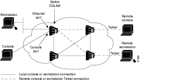
You can use either of two methods for configuring a DSLAM ( Figure 3-1):
•
•
Figure 3-1 Two Methods of Configuring a DSLAM
Port and Slot Configuration
The DSLAM contains an NI-2 card and up to 34 line (modem) cards depending on the DSLAM. The slot configurations on the different DSLAMs are as follows:
•
–
–
•
–
–
•
–
–
•
–
–
•
–
–
In all the chassis, the NI-2 card handles the network interfaces. The NI-2 card has either OC3 or DS3 interfaces.
Line cards are assigned ports 1 to 4 or 1 to 8 in consecutive slots. Table 3-1 lists NI-2 port assignments. Figure 3-2 shows the port connection arrangement.
Table 3-1 NI-2 Port Assignments
Switch, Ethernet
0/0
0/0
The ATM switch or Ethernet CPI port (internal).
Trunk
0/1
0/1
The trunk port connects to the network, either directly or through a subtended port in another DSLAM.
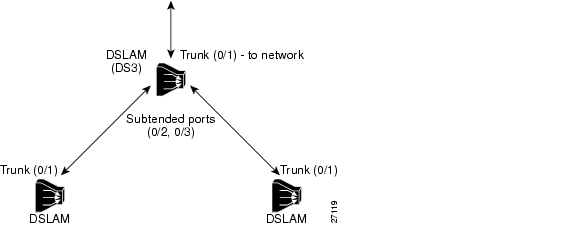
Subtend 1
0/2
0/2
A subtended port connects a second DSLAM to the network through a primary DSLAM. See Figure 3-3.
Subtend 2
N/A
0/3
The DS3 configuration has a second subtended port.
Figure 3-2 DSLAM Port Connections
Configuration Prerequisites
Obtain this information before you configure your DSLAM:
•
•
•
Verifying Installed DSLAM Software and Hardware
When you first power on your console and DSLAM, a screen similar to this appears:
Restricted Rights LegendUse, duplication, or disclosure by the Government issubject to restrictions as set forth in subparagraph(c) of the Commercial Computer Software - RestrictedRights clause at FAR sec. 52.227-19 and subparagraph(c) (1) (ii) of the Rights in Technical Data and ComputerSoftware clause at DFARS sec. 252.227-7013.cisco Systems, Inc.170 West Tasman DriveSan Jose, California 95134-1706The script then displays the banner information, including the software version, followed by the installed hardware configuration.
cisco ASP1 (R4600) processor with 16384K bytes of memory.Cisco Internetwork Operating System SoftwareIOS (tm) PNNI Software (LS-WP-M), Version XX.X(X.X.WAX.X.XX)Copyright (c) 1986-1998 by cisco Systems, Inc.Compiled Tue 11-Jan-98 02:59 byImage text-base: 0x600108D0, data-base: 0x603EE0008192K bytes of Flash internal SIMM (Sector size 256K).Press RETURN to get started!The DSLAM should now be operating correctly and transferring data.
Configuring the BOOTP Server
The BOOTP protocol automatically assigns an Ethernet IP address by adding the MAC and IP addresses of the Ethernet port to the BOOTP server configuration file. When the DSLAM boots, it automatically retrieves the IP address from the BOOTP server.
The DSLAM performs a BOOTP request only if the current IP address is set to 0.0.0.0. (This is the default for a new DSLAM or a DSLAM that has had its configuration file cleared using the erase startup-config command.)
To allow the DSLAM to retrieve its IP address from a BOOTP server you must first determine the MAC address of the DSLAM and then add that MAC address to the BOOTP configuration file on the BOOTP server.
Complete the following tasks to create a BOOTP server configuration file:
Step 1
Step 2
Step 3
Step 4
Example
This example BOOTP configuration file shows the newly added DSLAM entry:
# /etc/bootptab: database for bootp server (/etc/bootpd)## Blank lines and lines beginning with '#' are ignored.## Legend:## first field -- hostname# (may be full domain name)## hd -- home directory# bf -- bootfile# cs -- cookie servers# ds -- domain name servers# gw -- gateways# ha -- hardware address# ht -- hardware type# im -- impress servers# ip -- host IP address# lg -- log servers# lp -- LPR servers# ns -- IEN-116 name servers# rl -- resource location protocol servers# sm -- subnet mask# tc -- template host (points to similar host entry)# to -- time offset (seconds)# ts -- time servers<display truncated>########################################################################## Start of individual host entries#########################################################################Switch: tc=netcisco0: ha=0000.0ca7.ce00: ip=192.31.7.97:dross: tc=netcisco0: ha=00000c000139: ip=192.31.7.26:<information deleted>Setting the Subtend Node Identifier
In a subtended network configuration, the subtend node acts as the host node connecting all the nodes to the network. This node is identified to the network using the subtend-id command.
To set the subtend node identifier, use the following command:
DSLAM# subtend-id node#
In priviledged EXEC mode, identify node# as the subtend host node.
Example
This example sets the DSL subtend node identifier to node 12:
DSLAM> enablePassword:DSLAM# subtend-id 12Configuring the ATM Address
The DSLAM is autoconfigured with an ATM address using a hierarchical addressing model similar to the OSI network service access point (NSAP) addresses. PNNI uses this hierarchy to construct ATM peer groups. ILMI uses the first 13 bytes of this address as the switch prefix that it registers with end systems.
Note
Configuring ATM Addressing
This section describes the ATM addressing scheme and tells you how to
•
•
Using the ATM Default Addressing Scheme
This section describes the default addressing scheme and the features and implications of using this scheme.
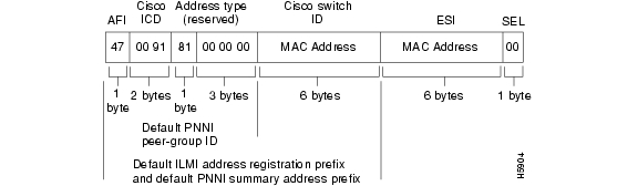
During the initial startup, the DSLAM generates an ATM address using the defaults shown in Figure 3-3.
Figure 3-3 ATM Address Format Defaults
The default addressing scheme includes:
•
•
•
•
•
•
If you use the default address format, these features and implications apply:
•
•
•
•
Manually Setting the ATM Address
You can configure a new ATM address that replaces the previous ATM address when running IISP software only, or that replaces the previous ATM address and generates a new PNNI node ID and peer group ID as follows:
•
http://www.cisco.com/univercd/cc/td/doc/product/atm/c8540/12_1/lhouse/sw_confg/ilmi_cnf.htm
•
http://www.cisco.com/univercd/cc/td/doc/product/atm/c8540/12_1/lhouse/sw_confg/access.htm
You can configure multiple addresses for a single switch and use this configuration during ATM address migration. ILMI registers end systems with multiple prefixes during this period until you remove an old address. PNNI automatically summarizes all the switch prefixes in its reachable address advertisement.
For operation with ATM addresses other than the autoconfigured ATM address, use the atm address command to manually assign a 20-byte ATM address to the switch. The atm address command address_template variable can be a full 20-byte address or a 13-byte prefix followed by ellipses (...). Entering the ellipses automatically adds one of the switch's 6-byte MAC addresses in the ESI portion and 0 in the selector portion of the address.
Caution
When the switch initially powers on without previous configuration data, the ATM interfaces configure automatically on the physical ports. The DSLAM uses ILMI and the physical card type to automatically derive:
•
•
•
•
•
You can accept the default ATM interface configuration or overwrite the default interface configuration using the CLI commands (see the ATM Switch Router Software Configuration Guide, Chapter 5 Configuring ATM Network Interfaces).
Modifying the Physical Layer Configuration of the Default ATM Interface
This section describes how to modify an ATM interface from the default configuration listed in Chapter 13, "Configuring In-Band Management." You can accept the ATM interface configuration or overwrite the default interface configuration using the CLI commands, which are described in ATM Switch Router Software Configuration Guide, Chapter 6, Configuring Virtual Connections.
Example
This example describes how to modify an OC-3 interface from the default settings to
•
•
•
To change the configuration of an ATM interface, follow these steps:
Example
This example shows how to disable cell-payload scrambling and STS-stream scrambling and changes the SONET mode of operation to Synchronous Digital Hierarchy/Synchronous Transfer Module 1 (SDH/STM-1) of OC-3 physical interface 0/0:
DSLAM(config)# interface atm 0/1DSLAM(config-if)# no scrambling cell-payloadDSLAM(config-if)# no scrambling sts-streamDSLAM(config-if)# sonet stm-1DSLAM(config-if)# exitDSLAM(config)#To display the physical interface configuration, use these privileged EXEC commands:
show controller atm slot/port
Show the physical layer configuration.
show running-config
Show the physical layer scrambling configuration.
Examples
This example displays the OC-3 physical interface configuration after you modify the defaults:
DSLAM# show controller atm 0/0Interface ATM0/0 is upHardware is IDT252PCI configuration registers:bus_no=0, device_no=1DeviceID=0x0004, VendorID=0x111D, Command=0x0006, Status=0x0290Class=0x02/0x03/0x00, Revision=0x01, LatencyTimer=0x20, CacheLineSize=0x04BaseAddr0=0x00000001, BaseAddr1=0x12001000, MaxLat=0x05, MinGnt=0x05SubsysDeviceID=0x0000, SubsysVendorID=0x0000slot 0, unit 0, subunit 0, fci_type 0x00000001,max_pak_size 4528particle size 576, pool size 400, cache size 1024, cache end 513NICStAR registers:data[0]: 76config: 32A19838status: F00404rxStatQH: 3C17390cellDropCt: 0vpiVciLookupErrorCt: 0invalidCellCt: 0rawCellHead: 3CA7440rawCellHandle: 3CDE004timer: 7EAAE9tstBase: 40000txStatQB: 3C12000txStatQH: 0txStatQT: 3C12BC8genPurpose: 8002vpiVciMsbMask: 0abrVbrSchTableDesc: 104C000abrReadyQueuePtr: 0vbrReadyQueuePtr: 0rateTableDesc: 14000txConnState: 70800068currentTxSchAddr: 403D4freeBufQueue0Sz: E000000AfreeBufQueue0Sz: E000000AfreeBufQueue1Sz: E000000BRECEIVE CONNECTION TABLE:VCD Control Buffer Handle DMA Address35 E02A8000 0 036 E02A8000 0 037 E02A8000 0 038 E02A8000 0 039 E02A8000 0 040 E02A8000 0 041 E02A8000 0 042 E02A8000 0 043 FD2A8000 77 3C97F4044 FD2A8000 FF 3CD10C045 E02A8000 0 046 E02A8000 0 047 E02A8000 0 048 E02A8000 0 049 E02A8000 0 050 E02A8000 0 051 E02A8000 0 052 E02A8000 0 053 E02A8000 0 054 E02A8000 0 055 FD2A8000 1B2 3CB771056 FD2A8000 176 3CC11F057 E02A8000 0 058 E02A8000 0 059 FD2A8000 1B5 3CB6F9060 FD2A8000 194 3CA5BF0enabled 0, disabled 0, throttled 0vc_per_vp 4096, max_vp 1, max_vc 4096, total_vc 9594Device values:IDT252 device number 0, base addr 0xB2001000,pci base off 0xA0DEAD01TX Status Queue Base 0xA3C12000TX Status Queue Tail 0xBF8Segmentation Channel Queue 0xA3C14000Rcv Stat Queue 0xA3C16000Rcv Stat Queue tail A3C17490FreeBufQ0Count 0 FreeBufQ0H 0 FreeBufQ0T 0FreeBufQ1Count 2 FreeBufQ1H A3C18510 FreeBufQ1T A3C18BD0Free Buff Queue 0 0xA3C18000Free Buff Queue 1 0xA3C18100Tx Buff Queue 0xA3C1A100This example displays the OC-3 physical layer scrambling configuration after you modify the defaults:
DSLAM# show running-configBuilding configuration...Current configuration : 12235 bytes!version 12.1no service padservice timestamps debug uptimeservice timestamps log uptimeno service password-encryption!hostname DSLAM!boot system flash:ni2-dsl-mz.v121_7_da.20010416slot 1 ATUC-1-4DMTslot 2 ATUC-1-4DMTslot 3 ATUC-1-4DMTslot 4 ATUC-1-4DMTslot 5 ATUC-1-4DMTslot 6 ATUC-1-4DMTslot 7 ATUC-1-4DMTslot 8 ATUC-1-4DMTslot 9 ATUC-4FLEXIDMTslot 10 NI-2-DS3-T1E1slot 12 ATUC-1-4DMTslot 13 ATUC-4FLEXIDMTslot 14 STUC-4-2B1Q-DIR-1slot 15 STUC-4-2B1Q-DIR-1slot 16 STUC-4-2B1Q-DIR-1slot 17 STUC-4-2B1Q-DIR-1slot 18 ATUC-1-DMT8slot 19 ATUC-1-4DMTslot 20 ATUC-1-DMT8slot 21 ATUC-1-4DMTslot 22 ATUC-1-4DMTslot 23 ATUC-1-4DMTslot 24 ATUC-1-4DMTslot 25 ATUC-1-4DMTslot 26 ATUC-1-4DMTslot 27 ATUC-4FLEXIDMTslot 28 ATUC-1-4DMTslot 29 ATUC-1-DMT8slot 30 ATUC-1-4DMTslot 31 STUC-4-2B1Q-DIR-1slot 32 ATUC-1-4DMT-Ino logging consoleenable password cisco!!!!!!dsl-profile defaultalarmsdmt check-bytes interleaved downstream 4 upstream 6dmt codeword-size downstream 16 upstream 8sdsl bitrate 528!!atm oam max-limit 1600no atm oam intercept end-to-endatm address 47.0091.8100.0000.0001.64ff.a980.0001.64ff.a980.00atm router pnnino aesa embedded-number left-justifiednode 1 level 56 lowestredistribute atm-static!atm ni2-switch trunk ATM0/IMA0!icm size 4194304!!interface ATM0/0no ip addressatm maxvp-number 0atm maxvc-number 4096atm maxvpi-bits 4!interface Ethernet0/0ip address 172.21.186.145 255.255.255.192!interface ATM0/2no ip addressno atm ilmi-keepaliveatm oam 0 5 seg-loopbackatm oam 0 16 seg-loopbackclock source loop-timedframing crc4lbo short gain10ima-group 0!ip default-gateway 172.21.186.129ip classlessip route 0.0.0.0 0.0.0.0 172.21.186.129no ip http server!!line con 0transport input noneline aux 0line vty 0 4password ciscologin!endConfiguring IP Interface Parameters
This section describes how to configure IP addresses on the DSLAM processor interfaces. You configure each IP address for one of the following types of connections:
•
•
Note
To configure the DSLAM to communicate using the Ethernet interface, provide the IP address and subnet mask bits for the interface as described in this section.
Defining an IP address
This section provides a summary of IP addressing concepts for those who are familiar with IP addressing.
Internet addresses are 32-bit values assigned to hosts that use the IP protocols. These addresses are in dotted decimal format (four decimal numbers separated by periods), such as 192.17.5.100. Each number is an 8-bit value between 0 and 255.
IP addresses are divided into three classes. These classes differ in the number of bits allocated to the network and host portions of the address:
•
•
•
The default IP address is none.
Enter your Internet address in dotted decimal format for each interface you plan to configure.
Defining Subnet Mask Bits
Subnetting is an extension of the Internet addressing scheme which allows multiple physical networks to exist within a single Class A, B, or C network. The subnet mask determines whether subnetting is in effect on a network. The usual practice is to use a few of the far-left bits in the host portion of the network address to assign a subnet field.
Internet addressing conventions allow a total of 24 host bits for Class A addresses, 16 host bits for Class B addresses, and 8 host bits for Class C addresses. When you are further subdividing your network (that is, subnetting your network), the number of host addressing bits is divided between subnetting bits and actual host address bits. You must specify a minimum of two host address bits, or the subnetwork is not populated by hosts.
Note
Table 3-2 provides a summary of subnetting parameters.
Table 3-2 Subnetting Parameters
A
1 to 126
8
22
2
B
128 to 191
16
14
2
You define subnet mask bits as a decimal number between
•
•
•
Note
To configure the IP address, perform these tasks, beginning in global configuration mode:
1.
interface ethernet slot/port
Select the interface to be configured.
2.
ip address A.B.C.D sub_net_A.B.C.D
Configure the IP and subnetwork address.
Example
This example shows how to configure the Ethernet CPU interface 0/0 with IP address 172.20.40.93 and subnetwork mask 255.255.255.0, and displays the interface information:
DSLAM# configure terminalEnter configuration commands, one per line. End with CNTL/Z.DSLAM(config)# interface ethernet 0/0DSLAM(config-if)# ip address 172.20.40.93 255.255.255.0DSLAM(config-if)# endDSLAM# show interface ethernet 0/0Ethernet0/0 is up, line protocol is upHardware is AmdP2, address is 0001.64ff.a97f (bia 0001.64ff.a97f)Internet address is 172.21.186.145/24MTU 1500 bytes, BW 10000 Kbit, DLY 1000 usec,reliability 255/255, txload 1/255, rxload 1/255Encapsulation ARPA, loopback not setKeepalive set (10 sec)ARP type: ARPA, ARP Timeout 04:00:00Last input 00:00:00, output 00:00:00, output hang neverLast clearing of "show interface" counters neverInput queue: 0/75/0/0 (size/max/drops/flushes); Total output drops: 0Queueing strategy: fifoOutput queue :0/40 (size/max)5 minute input rate 4000 bits/sec, 5 packets/sec5 minute output rate 2000 bits/sec, 3 packets/sec906236 packets input, 202482126 bytes, 0 no bufferReceived 889038 broadcasts, 0 runts, 0 giants, 0 throttles0 input errors, 0 CRC, 0 frame, 0 overrun, 0 ignored0 input packets with dribble condition detected163965 packets output, 21172110 bytes, 0 underruns0 output errors, 9 collisions, 1 interface resets0 babbles, 0 late collision, 33 deferred0 lost carrier, 0 no carrier0 output buffer failures, 0 output buffers swapped outDisplaying an IP Address
Use the show running-config command to display the CPU IP address:
DSLAM# show running-configBuilding configuration...Current configuration:!version XX.Xno service padservice udp-small-serversservice tcp-small-servers!hostname DSLAM!boot bootldr bootflash:/tftpboot/rbhide/ls-wp-mz.XXX-X.X.WA4.X.XX!ip host-routingip rcmd rcp-enableip rcmd rsh-enableip rcmd remote-username dplatzip domain-name cisco.comip name-server 198.92.30.32atm filter-set tod1 index 4 permit time-of-day 0:0 0:0atm qos default cbr max-cell-loss-ratio clp1plus0 12atm qos default vbr-nrt max-cell-loss-ratio clp1plus0 12atm address 47.0091.8100.0000.0041.0b0a.1081.0041.0b0a.1081.00atm address 47.0091.8100.5670.0000.0000.0000.0040.0b0a.1081.00atm route-optimization percentage-threshold 250atm router pnninode 1 level 56 lowestredistribute atm-static!<Information Deleted>!interface ATM0/1no keepalive!interface ATM0/0no ip addressno keepaliveatm maxvp-number 0atm pvc 0 any-vci encap aal5snap!interface Ethernet0/0ip address 172.20.40.93 255.255.255.0!no ip classlessatm route 47.0091.8100.0000... ATM0/0 scope 1atm route 47.0091.8100.0000.00... ATM0/0 e164-address 1234567!line con 0line aux 0line vty 0 4login!endTesting the Ethernet Connection
After you configure the IP addresses for the Ethernet interface, test for connectivity between the DSLAM and a host. The host can reside anywhere in your network. To test for Ethernet connectivity, use this command in EXEC mode:
ping ip ip_address
Test the configuration using the ping command. The ping command sends an echo request to the host specified in the command line.
For example, to test Ethernet connectivity from the DSLAM to a workstation with an IP address of 172.20.40.201, enter the command ping ip 172.20.40.201. If the DSLAM receives a response, this message appears:
DSLAM# ping ip 172.20.40.201Type escape sequence to abort.Sending 5, 100-byte ICMP Echos to 172.20.40.201, timeout is 2 seconds:!!!!!Success rate is 100 percent (5/5), round-trip min/avg/max = 1/202/1000 msConfiguring Network Clocking
This section describes how to configure network clocking and network clocking for the DSLAM. Each port has a transmit clock and derives its receive clock from the receive data. You can configure transmit clocking for each port in one of these ways:
•
•
The DSLAM receives derived clocking, along with data, from a specified interface. For example, in Figure 3-4 the DSLAM extracts transmit clocking, configured as priority one, from the data received at interface 0/1 and distributed as the transmit clock to the rest of the DSLAM. Interface 0/2 then uses network-derived transmit clocking received from interface 0/1.
Figure 3-4 Transmit Clock Distribution
Because the port providing the network clock source could fail, Cisco IOS software provides the ability to configure additional interfaces as clock sources with priorities 1 to 4.
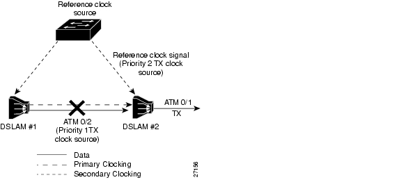
If the network clock source interface stops responding, the software switches to the next highest-configured priority network clock source. For example, Figure 3-5 shows:
•
•
•
•
•
Note
Figure 3-5 Transmit Clocking Priority Configuration Example
These sections describe network clocking:
•
•
•
Configuring Network Clock Priorities and Sources
To configure the network clocking priorities and sources, use these command in global configuration mode:
Examples
This example sets up the DSLAM's building-integrated time source (BITS) interface as the highest-priority clock source, then configures the BITS interface for T1 at 0.6db (0 to 133 feet, or 0 to 40.5 meters).
DSLAM# configure terminalEnter configuration commands, one per line. End with CNTL/Z.DSLAM(config)# network-clock-select 1 BITSDSLAM(config)# network-clock-select BITS T1 0.6dbThis example configures interface 0/1, the trunk, as the second-highest priority timing source.
DSLAM# configure terminalEnter configuration commands, one per line. End with CNTL/Z.DSLAM(config)# network-clock-select 2 atm 0/1This example configures the DSLAM's own system clock as the third-highest priority timing source.
DSLAM# configure terminalEnter configuration commands, one per line. End with CNTL/Z.DSLAM(config)# network-clock-select 3 systemThis example shows how to configure the network clock to revert back to the highest priority clock source after a failure:
DSLAM(config)# network-clock-select revertiveDSLAM(config)#Configuring the Transmit Clocking Source
To configure the location from which an interface receives its transmit clocking, perform these tasks, beginning in global configuration mode:
Note
Examples
This example configures ATM interface 0/1 to receive its transmit clocking from a network-derived source:
DSLAM(config)# interface atm 0/1DSLAM(config-if)# clock source network-derivedDSLAM(config-if)#This example displays the network clocking configuration shown in Figure 4-3:
DSLAM# show network-clocksPLL failed: 58886; PLL Passed: 1082982FAIL: 0; NCO: F984; REF: F982; ERR: 2; ERR_D: 0; MAG: -1;clock configuration is NON-RevertivePriority 1 clock source: BITS clockPriority 2 clock source: No clockPriority 3 clock source: No clockPriority 4 clock source: No clockPriority 5 clock source: System clockCurrent clock source:System clock, priority:5Nettime Config Register Contents:NDIV:FF SRC:2, SLOCK:0, TLOCK:0, NFAIL:0, E1:0, NSEL:0Trunk LED Register CLK_SEL:3BITS Register Contents:CR1: CB, CR2: 0, CR3: 0, ICR: 0, TSR: C1, PSR: 31, ESR: 77, CR4: 0BITS Source configured as: T1 Short Haul, 0-133ft/0.6db pulse, 100 ohm cable, 1nThis example displays the clock source configuration of ATM interface 0/2:
DSLAM# show running-configBuilding configuration...Current configuration:!version ZZ.Xno service padservice udp-small-serversservice tcp-small-servers!hostname DSLAM!boot bootldr bootflash:/tftpboot/ls-wp-mz.11X-X.X.WA4.X.XX!network-clock-select 2 ATM0/1<Information Deleted>!interface ATM0/2no keepaliveatm manual-well-known-vcatm access-group tod1 inatm pvc 0 35 rx-cttr 3 tx-cttr 3 interface ATM0/2 0 any-vci encap qsaalatm route-optimization soft-vc interval 360 time-of-day 18:0 5:0clock-source network-derived!<Information Deleted>This example displays the interface controller status of interface 0/0:
DSLAM# show controllers atm 0/0Interface ATM0/0 is upHardware is IDT252PCI configuration registers:bus_no=0, device_no=1DeviceID=0x0004, VendorID=0x111D, Command=0x0006, Status=0x0290Class=0x02/0x03/0x00, Revision=0x01, LatencyTimer=0x20, CacheLineSize=0x04BaseAddr0=0x00000001, BaseAddr1=0x12001000, MaxLat=0x05, MinGnt=0x05SubsysDeviceID=0x0000, SubsysVendorID=0x0000slot 0, unit 0, subunit 0, fci_type 0x00000001,max_pak_size 4528particle size 576, pool size 400, cache size 1024, cache end 513NICStAR registers:data[0]: 15Cconfig: 32A19838status: F00404rxStatQH: 3C177F0cellDropCt: 0vpiVciLookupErrorCt: 0invalidCellCt: 0rawCellHead: 3C9F580rawCellHandle: 3CDE004timer: AE396CtstBase: 40000txStatQB: 3C12000txStatQH: 0txStatQT: 3C13600genPurpose: 8002vpiVciMsbMask: 0abrVbrSchTableDesc: 104C000abrReadyQueuePtr: 0vbrReadyQueuePtr: 0rateTableDesc: 14000txConnState: 70800002currentTxSchAddr: 42298freeBufQueue0Sz: E000000AfreeBufQueue0Sz: E000000AfreeBufQueue1Sz: E000000BRECEIVE CONNECTION TABLE:VCD Control Buffer Handle DMA Address35 E02A8000 0 036 E02A8000 0 037 E02A8000 0 038 E02A8000 0 039 E02A8000 0 040 E02A8000 0 041 E02A8000 0 042 E02A8000 0 043 FD2A8000 9B 3C98F0044 FD2A8000 187 3CD010045 E02A8000 0 046 E02A8000 0 047 E02A8000 0 048 E02A8000 0 049 E02A8000 0 050 E02A8000 0 051 E02A8000 0 052 E02A8000 0 053 E02A8000 0 054 E02A8000 0 055 FD2A8000 1B2 3CB771056 FD2A8000 176 3CC11F057 E02A8000 0 058 E02A8000 0 059 FD2A8000 1B5 3CB6F9060 FD2A8000 194 3CA5BF0enabled 0, disabled 0, throttled 0vc_per_vp 4096, max_vp 1, max_vc 4096, total_vc 9594Device values:IDT252 device number 0, base addr 0xB2001000,pci base off 0xA0DEAD01TX Status Queue Base 0xA3C12000TX Status Queue Tail 0x1638Segmentation Channel Queue 0xA3C14000Rcv Stat Queue 0xA3C16000Rcv Stat Queue tail A3C178A0FreeBufQ0Count 0 FreeBufQ0H 0 FreeBufQ0T 0FreeBufQ1Count 1 FreeBufQ1H A3C1A040 FreeBufQ1T A3C1A040Free Buff Queue 0 0xA3C18000Free Buff Queue 1 0xA3C18100Tx Buff Queue 0xA3C1A100Providing Clock Synchronization Services
Any module in a DSLAM chassis capable of receiving and distributing a network timing signal can propagate that signal to any similarly capable module in the chassis. These entities are capable of receiving and distributing a primary reference source (PRS) for the clock:
•
•
•
Note
If you issue the network-clock-select command with the appropriate parameters, you can define a particular port in a DSLAM chassis (subject to the above limitations) to serve as the source of a PRS for the entire chassis or for other devices in the networking environment. This command is described in the "Configuring Network Clock Priorities and Sources" section.
You can also use the network-clock-select command to designate a particular port in a DSLAM chassis to serve as a master clock source for distributing a single clocking signal throughout the chassis or to other network devices. You can distribute this reference signal in any location the network needs to globally synchronize the flow of constant bit rate (CBR) data.
Configuring the Network Routing
For network routing, the default software image for the DSLAM contains the PNNI routing protocol. The PNNI protocol provides the route dissemination mechanism for complete plug-and-play capability. This section describes modifications you can make to the default PNNI or Interim-Interswitch Signaling Protocol (IISP) routing configurations.
Use the atm route command to configure a static route. Static route configuration allows ATM call setup requests to be forwarded on a specific interface if the addresses match a configured address prefix.
Note
Example
This example shows how to use the atm route command to configure the 13-byte peer group prefix as 47.0091.8100.567.0000.0ca7.ce01 at interface 0/1:
DSLAM(config)# atm route 47.0091.8100.567.0000.0ca7.ce01 atm 0/1DSLAM(config)#Configuring the Time, Date, and Month
Although not required, you can set several system parameters as part of the initial system configuration. To set the system parameters, perform these tasks, beginning in privileged EXEC mode:
1.
clock set hh:mm:ss day month year
Set the internal clock.
2.
configure [terminal]
Enter global configuration mode from the terminal.
3.
hostname name
Set the system name.
Examples
This example shows how to configure the time, date, and month using the clock set command:
DSLAM# clock set 15:01:00 17 October 2000This example shows how to configure the host name using the hostname command:
DSLAM# configure terminalEnter configuration commands, one per line. End with CNTL/Z.DSLAM(config)# hostname PublicationsPublications#This example shows how to confirm the clock setting using the show clock command:
Publications# show clock*15:03:12.015 UTC Fri Oct 17 2000Publications#Configuring SNMP Management
SNMP is an application-layer protocol that allows the SNMP manager and agent to communicate. SNMP provides a message format for sending information between an SNMP manager and an SNMP agent.
The SNMP system consists of three parts:
•
•
•
The SNMP manager can be part of a network management system (NMS), such as CiscoWorks.
The agent and MIB reside on the DSLAM. To configure SNMP on the DSLAM, you define the relationship between the manager and the agent.
The SNMP agent contains MIB variables whose values the SNMP manager can request or change. A manager can get a value from an agent or store a value into an agent. The agent gathers data from the MIB, the repository for information about device parameters and network data. The agent can also respond to a manager's requests to get or set data.
An agent can send unsolicited traps to the manager. Traps are messages that alert the SNMP manager to a condition on the network. Traps can indicate improper user authentication, restarts, link status (up or down), closing of a TCP connection, or loss of connection to a neighbor router or DSLAM.
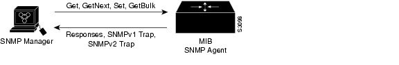
Figure 3-6 illustrates the communications relationship between the SNMP manager and agent.
Figure 3-6 Communication between an SNMP Agent and Manager
Figure 3-6 shows that a manager can send the agent requests to get and set MIB values. The agent can respond to these requests. Independent of this interaction, the agent can send unsolicited traps to the manager notifying the manager of network conditions.
Cisco supports the SNMP Version 1 protocol, referred to as SNMPv1, and the SNMP Version 2 protocol, referred to as SNMPv2. Cisco's implementation of SNMP supports all MIB II variables (as described in RFC 1213) and SNMP traps (as described in RFC 1215).
RFC 1447, "SNMPv2 Party MIB" (April 1993), describes the managed objects that correspond to the properties associated with SNMPv2 parties, SNMPv2 contexts, and access control policies, as defined by the SNMPv2 Administrative Model. RFC 1450, "SNMPv2 MIB," (April 1993) describes the managed objects that instrument the behavior of an SNMPv2 implementation. Cisco supports the MIB variables as required by the conformance clauses specified in these MIBs.
Cisco provides its own MIB with every system. One of the set of MIB objects provided is the Cisco Entity Asset MIB that enables the SNMP manager to gather data on system card descriptions, serial numbers, hardware and software revision levels, and slot locations.
Although SNMPv2 offers more robust support than SNMPv1, Cisco continues to support SNMPv1. Not all management stations have migrated to SNMPv2, and you must configure the relationship between the agent and the manager to use the version of SNMP supported by the management station.
SNMPv1 offers a community-based form of security defined through an IP address access control list and password. SNMPv2 offers richer security configured through an access policy that defines the relationship between a single manager and agent. SNMPv2 security includes message authentication support using the Message Digest 5 (MD5) algorithm, but because of the Data Encryption Standard (DES) export restrictions, it does not include encryption support through DES. SNMPv2 security provides data origin authentication, ensures data integrity, and protects against message stream modification.
In addition to enhanced security, SNMPv2 support includes a bulk retrieval mechanism and more detailed error message reporting to management stations. The bulk retrieval mechanism supports the retrieval of tables and large quantities of information, minimizing the number of round-trips required.
The SNMPv2 improved error handling support includes expanded error codes that distinguish different kinds of error conditions; these conditions are reported through a single error code in SNMPv1. Error return codes now report the error type. Three kinds of exceptions are also reported:
•
•
•
There is no specific command to enable SNMP. The first snmp-server command that you enter enables both versions of SNMP.
To configure SNMP support, perform the tasks in the appropriate sections:
•
•
•
To configure the relationship between the agent and the manager on the DSLAM, you need to know the version of the SNMP protocol that the management station supports. An agent can communicate with multiple managers, so you can configure the Cisco IOS software to support communications with one management station using the SNMPv1 protocol and another using the SNMPv2 protocol.
Configuring Support for Both SNMPv1 and SNMPv2
This section tells you how to configure support for both SNMPv1 and SNMPv2. The topics are:
•
•
•
•
•
Establishing the Contact, Location, and Serial Number of the SNMP Agent
You can set the system contact, location, and serial number of the SNMP agent so that these descriptions can be accessed through the configuration file. Use one or more of these commands in global configuration mode:
snmp-server contact text
Set the system contact string.
snmp-server location text
Set the system location string.
snmp-server chassis-id text
Set the system serial number.
Defining the Maximum SNMP Agent Packet Size
You can set the maximum packet size permitted when the SNMP agent is receiving a request or generating a reply. To do so, use this command in global configuration mode:
Monitoring SNMP Status
To monitor SNMP input and output statistics, including the number of illegal community string entries, errors, and requested variables, use this command in EXEC mode:
Disabling the SNMP Agent
To disable both versions of SNMP (SNMPv1 and SNMPv2) concurrently, use this command in global configuration mode:
Enabling the SNMP Agent Shutdown Mechanism
This section tells you how to enable a reload from the network after a system shutdown.
Using SNMP packets, a network management tool can send messages to users on both virtual terminals and the console. This facility operates in a similar fashion to the EXEC send command, but the SNMP request that causes the message to be issued to the users also specifies the action to be taken after the message is delivered. One possible action is a shutdown request. After a system shuts down, it is typically reloaded.
Reloading from the network is a powerful feature, and therefore is protected by the snmp-server system-shutdown global configuration command. If you do not issue this command, the shutdown mechanism does not enable.
To enable the SNMP agent shutdown mechanism, use this command in global configuration mode:
snmp-server system-shutdown
Use the SNMP message reload feature and request a system shutdown message.
To understand how to use this feature with SNMP requests, read the document mib.txt available by anonymous FTP from Cisco Connection Online.
Configuring SNMPv2 Support
SNMPv2 security requires that you create an access policy that defines the relationship between a manager and the agent. For each management station that the agent communicates with, you must create a separate access policy. Creating an access policy is a multiple-task process:
Step 1
Step 2
Step 3
Step 4
•
•
Figure 3-7 shows the information exchanged between the manager and the agent.
Figure 3-7 Flow of Management Operations Requests, Responses, and Traps
•
•
The agent sends trap messages to the manager in response to certain network conditions. Trap messages are unsolicited and are not related to the request/response communication exchange between the manager and the agent that occurs in relation to MIB variables. For any given manager and agent relationship, the privileges defined in the access policy constrain communications to a specific set of operations.
You must create access policies for
•
•
Each time a network address changes on a management station, you must reconfigure the access policy to reflect the new information for the management station.
Configuring Support for SNMPv2
To configure support for SNMPv2, perform the tasks described in the following sections:
•
•
•
•
•
After you create a record, you can modify the record contents by changing one or more of the record values. To do this, issue the command again, naming the record that you created originally. You must fully specify the record values, including the argument values, to remain unchanged.
Creating or Modifying an SNMP View Record
To create or modify an SNMP view record, use this command in global configuration mode:
snmp-server view view-name oid-tree {included | excluded}
Create or modify a view record.
To remove a view record, use the no snmp-server view command.
Creating or Modifying an SNMP Context Record
To create or modify an SNMP context record, use this command in global configuration mode:
snmp-server context context-name context-oid view-name
Create or modify a context record.
To remove a context entry, use the no snmp-server context command. Specify only the name of the context. The name identifies the context to be deleted.
Creating or Modifying an SNMPv2 User Record
To create or modify an SNMPv2 user record, use this command in global configuration mode:
snmp-server user user-name user-oid [protocol-address] [packetsize size] [local | remote] [authentication md5 key [clock clock] [lifetime lifetime]
Create or modify a user record.
To remove a user record, use the no snmp-server user command.
Creating an SNMPv2 Access Policy
To create or modify an SNMPv2 access policy, use this command in global configuration mode:
snmp-server access-policy destination-party source-party context privileges
Create or modify an access policy.
To remove an SNMPv2 access policy, use the no snmp-server access-policy command. Specify all three arguments to correctly identify the access policy to be deleted. A difference of one value constitutes a unique access policy entry.
Defining SNMPv2 Trap Operations
A trap is an unsolicited message sent by an SNMP agent to an SNMP manager indicating that some event has occurred. The SNMP trap operations allow you to configure the Cisco IOS software to send information to a network management application when a particular event occurs. You can specify these features for SNMPv2 agent trap operations:
•
•
•
•
•
•
To define the recipient of the trap message, configure a user record for the manager, including the protocol address, and specify the user record as the destination user for the snmp-server access policy command.
To define traps for the agent to send to the manager, use one or more of these commands in global configuration mode:
Because SNMP traps are inherently unreliable but too important to lose, the DSLAM stores at least one syslog message (the most recent trap), in a history table. You can specify the level of syslog traps (Cisco Syslog MIB) stored in the history table and sent to the SNMP network management station.
Configuring SNMPv1 Support
If the SNMP manager supports only the SNMPv1 protocol, you must configure the relationship between the manager and the agent using SNMPv1 support.
Using the snmp-server community command, specify a string and, optionally, a MIB view and an access list. The string is used as a password. The MIB view defines the subset of all MIB objects that the given community can access. The access list identifies the IP addresses of systems on which SNMPv1 managers reside that might use the community string to gain access to the SNMPv1 agent.
To configure support for SNMPv1, perform the tasks in these sections:
•
•
Creating or Modifying Access Control for an SNMPv1 Community
You can configure a community string, which acts like a password, to permit access to the agent on the DSLAM. Optionally, you can associate a list of IP addresses with that community string to permit only managers with these IP addresses to use the string.
To configure a community string, use this command in global configuration mode:
snmp-server community string [view view-name] [ro | rw] [access-list number]
Define the community access string.
You can configure one or more community strings. To remove a specific community string, use the no snmp-server community command.
Defining SNMP Trap Operations for SNMPv1
The SNMP trap operations allow a system administrator to configure the agent to send information to a manager when a particular event occurs. You can specify these features for SNMP server trap operations:
•
•
•
•
•
•
To define traps for the agent to send to the specified manager, perform these tasks in global configuration mode:
Because SNMP traps are inherently unreliable but too important to lose, at least one syslog message, the DSLAM stores the most recent trap in a history table. You can specify the level of syslog traps (Cisco Syslog MIB) stored in the history table and sent to the SNMP network management station.
Configuring SNMP RMON Support
Remote Monitoring (RMON)
•
•
RMON, used in conjunction with the SNMP agent in the DSLAM, allows you to
•
•
Combining RMON alarms and events with existing MIBs allows you to choose where monitoring occurs.
RMON can be very data- and processor-intensive. Measure usage effects to ensure that DSLAM performance is not degraded and to minimize excessive management traffic overhead. Native mode is less intensive than promiscuous mode.
Cisco IOS software images are available in versions with or without the explicit RMON option. Images without the explicit RMON option include limited RMON support (RMON alarms and event groups only). Images with the RMON option include support for all nine groups (statistics, history, alarms, hosts, hostTopN, matrix, filter, capture, and event). As a security precaution, support for the packet capture group allows capture of packet header information only; data payloads are not captured.
Note
To set an RMON alarm or event, use one of these commands in global configuration mode:
You can set an alarm on any MIB object in the access server. To disable an alarm, you must enable the no form of this command on each alarm you configure. You cannot disable all the alarms you configure at one time.
Refer to RFC 1757 to learn more about alarms and events and how they interact with each other.
To display the current RMON status, use these EXEC commands:
show rmon
or
show rmon task
Display general RMON statistics.
show rmon alarms
Display the RMON alarm table.
show rmon events
Display the RMON event table.
Examples
This example shows how to enable the rmon event command:
DSLAM# rmon event 1 log trap eventtrap description "High ifOutErrors" owner sdurhamThis example shows how to configure this RMON event:
•
•
•
•
•
This example shows how to configure an RMON alarm using the rmon alarm command:
DSLAM# rmon alarm 10 ifEntry.20.1 20 delta rising-threshold 15 1 falling-threshold 0 owner
jjjohnson
This example shows how to configure this RMON alarm:
•
•
•
•
Possible events include a log entry or an SNMP trap. If the ifEntry.20.1 value changes by 0, the alarm is reset and can be triggered again.
Storing the Configuration
After you complete autoconfiguration and any manual configurations, copy the configuration into nonvolatile random-access memory (NVRAM). If you power off your DSLAM prior to saving the configuration in NVRAM you lose all manual configuration changes.
An example of the copy running-config command is:
DSLAM# copy running-config startup-configBuilding configuration...[OK]Testing the Configuration
After you finish configuring the DSLAM, you can use the commands described in this section to confirm the hardware, software, and interface configuration:
•
•
•
•
•
•
•
•
•
•
•
•
Confirming the Hardware Configuration
Use the show hardware command to confirm the correct hardware installation. For example:
DSLAM# show hardwareChassis Type: C6260I/O Card: 6260-E1-IOSlot 1 : ATUC-1-4DMT Slot 17: STUC-4-2B1Q-DIR-1Slot 2 : ATUC-1-4DMT Slot 18: ATUC-1-DMT8Slot 3 : ATUC-1-4DMT Slot 19: ATUC-1-4DMTSlot 4 : ATUC-1-4DMT Slot 20: ATUC-1-DMT8Slot 5 : ATUC-1-4DMT Slot 21: ATUC-1-4DMTSlot 6 : ATUC-1-4DMT Slot 22: ATUC-1-4DMTSlot 7 : ATUC-1-4DMT Slot 23: ATUC-1-4DMTSlot 8 : ATUC-1-4DMT Slot 24: ATUC-1-4DMTSlot 9 : ATUC-4FLEXIDMT Slot 25: ATUC-1-4DMTSlot 10: NI-2-DS3-T1E1 Slot 26: ATUC-1-4DMTSlot 11: EMPTY Slot 27: ATUC-4FLEXIDMTSlot 12: ATUC-1-4DMT Slot 28: ATUC-1-4DMTSlot 13: ATUC-4FLEXIDMT Slot 29: ATUC-1-DMT8Slot 14: STUC-4-2B1Q-DIR-1 Slot 30: ATUC-1-4DMTSlot 15: STUC-4-2B1Q-DIR-1 Slot 31: STUC-4-2B1Q-DIR-1Slot 16: STUC-4-2B1Q-DIR-1 Slot 32: ATUC-1-4DMT-IFan Module 1: Present 2: PresentPower Supply Module 1: 6260-PEM-ACPower Supply Module 2: 6260-PEM-ACConfirming the Software Version
Use the show version command to confirm the correct version and type of software and the configuration register are installed. For example:
DSLAM# show versionCisco Internetwork Operating System SoftwareIOS (tm) NI2 Software (NI2-DSL-M), Experimental Version 12.1(20010416:212622) []Copyright (c) 1986-2001 by cisco Systems, Inc.Compiled Mon 16-Apr-01 17:26 by chrelImage text-base: 0x800082C0, data-base: 0x8132A000ROM: System Bootstrap, Version 12.0(5)DA, EARLY DEPLOYMENT RELEASE SOFTWARE (fc)BOOTFLASH: NI2 Software (NI2-DBOOT-M), Version 12.1(6)DA, EARLY DEPLOYMENT RELE)6260_E1IMA uptime is 1 week, 6 days, 5 hours, 48 minutesSystem returned to ROM by reloadSystem image file is "flash:ni2-dsl-mz.v121_7_da.20010416"cisco 6260 (NI2) processor with 60416K/5120K bytes of memory.RC64475 CPU at 100Mhz, Implementation 48, Rev 0.0Bridging software.1 Ethernet/IEEE 802.3 interface(s)112 DMT DSL Port interface(s)20 SDSL DSL Port interface(s)13 ATM network interface(s)522232 bytes of non-volatile configuration memory.4096K bytes of Boot Flash (Sector size 128K).16384K bytes of Flash internal SIMM (Sector size 256K).Configuration register is 0x2102Confirming the Ethernet Configuration
Use the show interface ethernet command to confirm the Ethernet interface is configured correctly. For example:
DSLAM# show interface ethernet 0/0Ethernet0/0 is up, line protocol is upHardware is AmdP2, address is 0001.64ff.a97f (bia 0001.64ff.a97f)Internet address is 172.21.186.145/24MTU 1500 bytes, BW 10000 Kbit, DLY 1000 usec,reliability 255/255, txload 1/255, rxload 1/255Encapsulation ARPA, loopback not setKeepalive set (10 sec)ARP type: ARPA, ARP Timeout 04:00:00Last input 00:00:00, output 00:00:00, output hang neverLast clearing of "show interface" counters neverInput queue: 0/75/0/0 (size/max/drops/flushes); Total output drops: 0Queueing strategy: fifoOutput queue :0/40 (size/max)5 minute input rate 2000 bits/sec, 3 packets/sec5 minute output rate 1000 bits/sec, 2 packets/sec910869 packets input, 202979554 bytes, 0 no bufferReceived 890807 broadcasts, 0 runts, 0 giants, 0 throttles0 input errors, 0 CRC, 0 frame, 0 overrun, 0 ignored0 input packets with dribble condition detected166029 packets output, 21332341 bytes, 0 underruns0 output errors, 9 collisions, 1 interface resets0 babbles, 0 late collision, 33 deferred0 lost carrier, 0 no carrier0 output buffer failures, 0 output buffers swapped outConfirming the ATM Address
Use the show atm addresses command to confirm correct configuration of the ATM address for the DSLAM. For example:
DSLAM# show atm addressesSwitch Address(es):47.0091.8100.0000.0001.64ff.a980.0001.64ff.a980.00 activeNOTE: Switch addresses with selector bytes 01 through 7Fare reserved for use by PNNI routingPNNI Local Node Address(es):47.0091.8100.0000.0001.64ff.a980.0001.64ff.a980.01 Node 1Soft VC Address(es):47.0091.8100.0000.0001.64ff.a980.4000.0c98.0020.00 ATM0/247.0091.8100.0000.0001.64ff.a980.4000.0c98.0030.00 ATM0/3Soft VC Address(es) for Frame Relay Interfaces :ILMI Switch Prefix(es):47.0091.8100.0000.0001.64ff.a980ILMI Configured Interface Prefix(es):LECS Address(es):Testing the Ethernet Connection
After you configure the IP addresses for the Ethernet interface, test for connectivity between the DSLAM and a host. The host can reside in any location on your network. To test for Ethernet connectivity, use this command:
ping ip ip_address
Test the configuration using the ping command. The ping command sends an echo request to the host specified in the command line.
For example, to test Ethernet connectivity from the DSLAM to a workstation with an IP address of 172.20.40.201, enter the command ping ip 172.20.40.201. If the DSLAM receives a response, this message appears:
DSLAM# ping ip 172.20.40.201Type escape sequence to abort.Sending 5, 100-byte ICMP Echos to 172.20.40.201, timeout is 2 seconds:!!!!!Success rate is 100 percent (5/5), round-trip min/avg/max = 1/202/1000 msConfirming the ATM Connections
Use the ping atm command to confirm that the ATM interfaces are configured correctly. For example:
DSLAM# ping atm interface atm 0/1 5 seg-loopbackType escape sequence to abort.Sending Seg-Loopback 5, 53-byte OAM Echoes to a neighbour,timeout is 5 seconds:!!!!!Success rate is 100 percent (5/5), round-trip min/avg/max = 1/1/4 msDSLAM#Confirming the ATM Interface Configuration
Use the show atm interface command to confirm the atm interfaces are configured correctly. For example:
DSLAM# show atm interfaceInterface: ATM0/0 Port-type: cpuIF Status: UP Admin Status: UPAuto-config: disabled AutoCfgState: not applicableIF-Side: not applicable IF-type: not applicableUni-type: not applicable Uni-version: not applicableMax-VPI-bits: 4 Max-VCI-bits: 14Max-VP: 0 Max-VC: 4096ConfMaxSvpcVpi: 0 CurrMaxSvpcVpi: 0ConfMaxSvccVpi: 0 CurrMaxSvccVpi: 0ConfMinSvccVci: 35 CurrMinSvccVci: 35Configured virtual links:PVCLs SoftVCLs SVCLs TVCLs PVPLs SoftVPLs SVPLs Total-Cfgd Inst-Conns26 0 0 0 0 0 0 26 26Logical ports(VP-tunnels): 0Input cells: 106840 Output cells: 05 minute input rate: 0 bits/sec, 0 cells/sec5 minute output rate: 0 bits/sec, 0 cells/secInput AAL5 pkts: 0, Output AAL5 pkts: 0, AAL5 crc errors: 0Interface: ATM0/2 Port-type: e1_ima_linkIF Status: UP Admin Status: UPAuto-config: enabled AutoCfgState: waiting for response from peerIF-Side: Network IF-type: UNIUni-type: Private Uni-version: V3.0Max-VPI-bits: 8 Max-VCI-bits: 14Max-VP: 255 Max-VC: 16383ConfMaxSvpcVpi: 255 CurrMaxSvpcVpi: 255ConfMaxSvccVpi: 255 CurrMaxSvccVpi: 255ConfMinSvccVci: 35 CurrMinSvccVci: 35Svc Upc Intent: pass Signalling: EnabledATM Address for Soft VC: 47.0091.8100.0000.0001.64ff.a980.4000.0c98.0020.00Configured virtual links:PVCLs SoftVCLs SVCLs TVCLs PVPLs SoftVPLs SVPLs Total-Cfgd Inst-Conns2 0 0 0 1 0 0 3 2Logical ports(VP-tunnels): 0Input cells: 925 Output cells: 745 minute input rate: 0 bits/sec, 0 cells/sec5 minute output rate: 0 bits/sec, 0 cells/secInput AAL5 pkts: 0, Output AAL5 pkts: 0, AAL5 crc errors: 0[additional interfaces deleted]Confirming the Interface Status
Use the show atm status command to confirm the status of ATM interfaces. For example:
DSLAM# show atm statusNUMBER OF INSTALLED CONNECTIONS: (P2P=Point to Point, P2MP=Point to MultiPoint,)Type PVCs SoftPVCs SVCs TVCs PVPs SoftPVPs SVPs TotalP2P 26 0 0 0 0 0 0 26P2MP 0 0 0 0 0 0 0 0MP2P 0 0 0 0 0 0 0 0TOTAL INSTALLED CONNECTIONS = 26PER-INTERFACE STATUS SUMMARY AT 07:15:04 UTC Wed Oct 18 2000:Interface IF Admin Auto-Cfg ILMI Addr SSCOP HelloName Status Status Status Reg State State State------------- -------- ------------ -------- ------------ --------- --------ATM0/0 UP up n/a UpAndNormal Idle n/aATM0/2 UP up waiting Restarting Idle n/aConfirming Virtual Channel Connections
Use the show atm vc command to confirm the status of ATM virtual channels. For example:
DSLAM# show atm vcInterface VPI VCI Type X-Interface X-VPI X-VCI Encap StatusATM0/0 0 36 PVC ATM0/2 0 16 ILMI DOWNATM0/0 0 38 PVC ATM0/2 0 5 QSAAL DOWNATM0/0 0 500 PVC ATM0/1 0 500 SNAP UPATM0/1 0 500 PVC ATM0/0 0 500 SNAP UPATM0/2 0 5 PVC ATM0/0 0 38 QSAAL DOWNATM0/2 0 16 PVC ATM0/0 0 36 ILMI DOWNConfirming the Running Configuration
Use the show running-config command to confirm that the configuration being used is configured correctly. For example:
DSLAM# show running-configBuilding configuration...Current configuration : 12407 bytes!version 12.1no service padservice timestamps debug uptimeservice timestamps log uptimeno service password-encryption!hostname 6260_E1IMA!boot system flash:ni2-dsl-mz.v121_7_da.20010416slot 1 ATUC-1-4DMTslot 2 ATUC-1-4DMTslot 3 ATUC-1-4DMTslot 4 ATUC-1-4DMTslot 5 ATUC-1-4DMTslot 6 ATUC-1-4DMTslot 7 ATUC-1-4DMTslot 8 ATUC-1-4DMTslot 9 ATUC-4FLEXIDMTslot 10 NI-2-DS3-T1E1slot 12 ATUC-1-4DMTslot 13 ATUC-4FLEXIDMTslot 14 STUC-4-2B1Q-DIR-1slot 15 STUC-4-2B1Q-DIR-1slot 16 STUC-4-2B1Q-DIR-1slot 17 STUC-4-2B1Q-DIR-1slot 18 ATUC-1-DMT8slot 19 ATUC-1-4DMTslot 20 ATUC-1-DMT8slot 21 ATUC-1-4DMTslot 22 ATUC-1-4DMTslot 23 ATUC-1-4DMTslot 24 ATUC-1-4DMTslot 25 ATUC-1-4DMTslot 26 ATUC-1-4DMTslot 27 ATUC-4FLEXIDMTslot 28 ATUC-1-4DMTslot 29 ATUC-1-DMT8slot 30 ATUC-1-4DMTslot 31 STUC-4-2B1Q-DIR-1slot 32 ATUC-1-4DMT-Ino logging consoleenable password cisco!!!!!!dsl-profile defaultalarmsdmt check-bytes interleaved downstream 4 upstream 6dmt codeword-size downstream 16 upstream 8sdsl bitrate 528!atm oam max-limit 1600no atm oam intercept end-to-endatm address 47.0091.8100.0000.0001.64ff.a980.0001.64ff.a980.00atm router pnnino aesa embedded-number left-justifiednode 1 level 56 lowestredistribute atm-static!atm ni2-switch trunk ATM0/IMA0!icm size 4194304!!interface ATM0/0no ip addressatm maxvp-number 0atm maxvc-number 4096atm maxvpi-bits 4!interface Ethernet0/0ip address 172.21.186.145 255.255.255.0!interface ATM0/2no ip addressno atm ilmi-keepaliveatm oam 0 5 seg-loopbackatm oam 0 16 seg-loopbackclock source loop-timedframing crc4lbo short gain10ima-group 0!ip default-gateway 172.21.186.129ip classlessip route 0.0.0.0 0.0.0.0 172.21.186.129no ip http server!atm route 47.0091.8100.5670.0000.ca7c.e01... ATM0/0snmp-server trap-source ATM0/0snmp-server enable traps configsnmp-server enable traps alarms!!line con 0transport input noneline aux 0line vty 0 4password ciscologin!endConfirming the Saved Configuration
Use the show startup-config command to confirm that the configuration saved in NVRAM is configured correctly. For example:
DSLAM# show startup-configUsing 1657 out of 522232 bytes!! Last configuration change at 11:35:31 EDT Thu Jun 3 1999! NVRAM config last updated at 11:40:08 EDT Thu Jun 3 1999!version XX.Xno service padservice timestamps debug uptimeservice timestamps log uptimeno service password-encryptionservice internal!hostname ni2-3!enable password lab!!dmt-profile defaultnetwork-clock-select 1 ATM0/1network-clock-select 2 systemip subnet-zeroip host-routingip domain-name cisco.comip name-server 171.69.204.11!atm address 47.0091.8100.0000.007b.f444.7801.007b.f444.7801.00atm router pnnino aesa embedded-number left-justifiednode 1 level 56 lowestredistribute atm-static!clock timezone EST -5clock summer-time EDT recurring!process-max-time 200!interface ATM0/0ip address 70.0.0.2 255.0.0.0no ip directed-broadcastmap-group testatm cac service-category abr denyatm maxvp-number 0!interface Ethernet0/0ip address 172.27.32.157 255.255.255.0no ip directed-broadcastno ip proxy-arpno keepalive!interface ATM0/1no ip addressno ip directed-broadcastno atm auto-configurationno atm ilmi-keepaliveno atm address-registrationno atm ilmi-enableatm cac service-category abr denyatm manual-well-known-vcatm nniatm pvc 0 500 interface ATM0/0 0 500 encap aal5snapatm oam 0 500 seg-loopback!interface ATM0/2no ip addressno ip directed-broadcastno atm ilmi-keepaliveatm cac service-category abr deny!ip default-gateway 172.27.144.4ip classless!!map-list testip 70.0.0.1 atm-vc 500!line con 0exec-timeout 0 0transport input noneline aux 0line vty 0 4exec-timeout 0 0password lablogin!sntp server 171.69.204.139end
![]()
![]()
![]()
![]()
![]()
![]()
![]()
![]()
Posted: Fri Dec 3 14:15:06 PST 2004
All contents are Copyright © 1992--2004 Cisco Systems, Inc. All rights reserved.
Important Notices and Privacy Statement.