|
|

Table Of Contents
Configuring In-Band Management
Configuring In-Band Management
Configuring In-Band Management in an SVC Environment
Configuring In-Band Management in a PVC Environment
Mapping a Protocol Address to a PVC
Configuring a PVC-Based Map List
Configuring an SVC-Based Map List
Configuring In-Band Management
This chapter describes how to configure in-band management on Cisco DSLAMs with NI-2.
This chapter includes the sections:
•
Configuring In-Band Management
•
Configuring In-Band Management
The DSLAM allows in-band management via the trunk interface. In-band management uses the IP over ATM protocol. The DSLAM is a client in an IP over ATM environment; it provides none of the ARP server functions found in the LS1010. SNMP is used above the IP layer to provide management functionality. This section describes configuring a port on a switch to allow in-band management of the switch CPU.
Configuring In-Band Management in an SVC Environment
This section describes in-band management in an SVC environment. In-band management requires configuring the DSLAM with its own ATM address and that of a single ATM Address Resolution Protocol (ARP) server.
In-band management in an SVC environment is configured by the DSLAM in the following process:
Step 1
Step 2
Step 3
Step 4
Note
After the connection is known to both clients, they communicate directly over the SVC.
The ATM ARP client (the DSLAM) tries to maintain a connection to the ATM ARP server. The ATM ARP server can remove the connection, but the client attempts once each minute to bring the connection back up. No error messages are generated for a failed connection, but the client does not route packets until the ATM ARP server is connected and translates IP network addresses.
For each packet with an unknown IP address, the client (the DSLAM) sends an ATM ARP request to the ARP server. Until that address is resolved, any IP packet routed to the ATM interface causes the client to send another ATM ARP request.
Configuring ATM ARP
In an SVC environment, configure the ATM ARP mechanism on the interface by performing these tasks, beginning in global configuration mode:
1.
interface atm slot/port[.sub_inter#]
Select the interface to be configured.
2.
atm nsap-address nsap-address
or
atm esi-address esi-addressSpecify the NSAP ATM address of the interface.
or
Specify the end-system-identifier (ESI) address of the interface.3.
ip address address mask
Specify the IP address of the interface.
4.
atm arp-server nsap nsap-address
Specify the ATM address of the ATM ARP server.
5.
exit
Exit interface configuration mode.
6.
atm route {addr-prefix1 } atm 0/0 internal
Configure a static route through the switch to the CPU interface. See the note.
1 First 19 bytes of the NSAP address.
Note
NSAP Address Example
This example shows how to configure CPU interface 0/0 of client A using the NSAP address:
Client A(config)# interface atm 0/0Client A(config-if)# $dress 47.0091.8100.0000.1111.1111.1111.1111.1111.1111.00Client A(config-if)# ip address 123.233.45.1 255.255.255.0Client A(config-if)# $dress 47.0091.8100.0000.1111.1111.1111.2222.2222.2222.00Client A(config-if)# exitClient A(config)# $0.0000.1111.1111.1111.1111.1111.1111 atm 0/0 internalThese commands:
1.
2.
3.
4.
5.
6.
Note
ESI Example
This example shows how to configure CPU interface 0/0 of client A (Figure 13-1), using the ESI:
Client A(config)# interface atm 0/0Client A(config-if)# atm esi-address 0041.0b0a.1081.40Client A(config-if)# ip address 123.233.45.1 255.255.255.0Client A(config-if)# $7.0091.8100.0000.1111.1111.1111.2222.2222.2222.00Client A(config-if)# exitThese commands:
1.
2.
3.
4.
Note
Show ATM ARP Example
In this example, the show atm arp command displays the configuration of the switch interface 0/0:
Switch# show atm arpNote that a '*' next to an IP address indicates an active callIP Address TTL ATM AddressATM0/0:* 10.0.0.5 19:21 4700918100567000000000112200410b0a108140Show ATM MAP Example
This example displays the map-list configuration of the switch static map and IP-over-ATM interfaces:
Switch# show atm mapMap list ATM0/0_ATM_ARP : DYNAMICarp maps to NSAP 36.0091810000000003D5607900.0003D5607900.00, connection up, VPI=0 VCI=73, ATM0/0ip 5.1.1.98 maps to NSAP 36.0091810000000003D5607900.0003D5607900.00, broadcast, connection up, VPI=0 VCI=77, ATM0/0Map list ip : PERMANENTip 5.1.1.99 maps to VPI=0 VCI=200Configuring In-Band Management in a PVC Environment
This section describes how to configure in-band management in a PVC environment. The ATM Inverse ARP mechanism is applicable to networks that use PVCs, where connections are established but the network addresses of the remote ends are not known.
In a PVC environment, configure the ATM Inverse ARP mechanism by performing the tasks:
Repeat these tasks for each PVC you want to create.
The inarp minutes interval specifies how often Inverse ARP datagrams are sent on this virtual circuit. The default value is 15 minutes.
Note
Example
This example configures an IP-over-ATM interface in a PVC environment and displays the map-list configuration of the switch static map and in-band management interfaces.
These commands:
1.
2.
3.
4.
DSLAM(config)# interface atm 0/0DSLAM(config)# ip address 11.11.11.11DSLAM(config-if)# atm pvc 0 100 encap aal5snap inarp 10 interface atm 0/0 50 100DSLAM# show atm mapMap list yyy : PERMANENTip 1.1.1.2 maps to VPI=0 VCI=200Map list zzz : PERMANENTMap list a : PERMANENTMap list 1 : PERMANENTMap list ATM0/0_ATM_ARP : DYNAMICarp maps to NSAP 47.009181005670000000001122.00410B0A1081.40, connection up, VPI=0 VCI=85, ATM0/0ip 10.0.0.5 maps to NSAP 47.009181005670000000001122.00410B0A1081.40, broadcast, ATM0/0Mapping a Protocol Address to a PVC
The ATM interface supports a static mapping scheme that identifies the ATM address of remote hosts or switches. This IP address is specified as a PVC or as an NSAP address for SVC operation. Configuration for both PVC and SVC map lists are described in these sections:
•
•
Configuring a PVC-Based Map List
This section describes how to map a PVC to an address, which is a required task if you are configuring a PVC.
You can enter mapping commands as groups. To do so, create a map list and then associate the map list with an interface. Begin with these tasks:
You can create multiple map lists, but only one map list can be associated with an interface. Different map lists can be associated with different interfaces.
Example
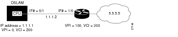
Figure 13-1 illustrates a connection configured with a PVC map list.
Figure 13-1 PVC Map List Configuration Example
The commands used to configure the connection in Figure 13-1 are
DSLAM(config)# ip host-routingDSLAM(config)# interface atm 0/0DSLAM(config-if)# ip address 1.1.1.1 255.0.0.0DSLAM(config-if)# map-group yyyDSLAM(config-if)# atm pvc 0 200 encap aal5snap interface atm 0/1 100 300DSLAM(config-if)# exitDSLAM(config)# ip route 1.1.1.1 255.0.0.0 1.1.1.2DSLAM(config)# map-list yyyDSLAM(config-map-list)# ip 1.1.1.2 atm-vc 200DSLAM(config-map-list)# endThese commands enable IP host-based routing.
1.
2.
3.
4.
5.
6.
7.
Example
This example displays the map-list configuration of the DSLAM at interface 0/0:
DSLAM# show atm mapMap list yyy : PERMANENTip 1.1.1.2 maps to VPI=0 VCI=200Configuring an SVC-Based Map List
This section describes how to map an SVC to an NSAP address. This is a required task if you are configuring an SVC.
You can enter mapping commands as groups. To do so, create a map list and then associate it with the map list interface. Perform these tasks:
You can create multiple map lists, but only one map list can be associated with an interface. Different map lists can be associated with different interfaces.
Examples
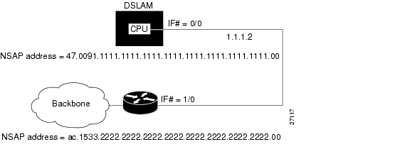
Figure 13-2 illustrates an SVC connection configured with a map list.
Figure 13-2 SVC Map List Configuration Example
This example shows the commands used to configure the connection in Figure 13-2:
DSLAM(config)# ip host-routingDSLAM(config)# interface atm 0/0DSLAM(config-if)# ip address 1.1.1.1 255.0.0.0DSLAM(config-if)# map-group zzzDSLAM(config-if)# atm nsap-address 47.0091.1111.1111.1111.1111.1111.1111.1111.1111.00DSLAM(config-if)# exitDSLAM(config)# ip route 1.1.1.1 255.0.0.0 1.1.1.2DSLAM(config)# map-list zzzDSLAM(config-map-list)# ip 1.1.1.2 atm-nsap ac.1533.2222.2222.2222.2222.2222.2222.2222.2222.00DSLAM(config-map-list)# endThese commands:
1.
2.
3.
4.
5.
6.
7.
8.
9.
Example
This example displays the map-list configuration of the DSLAM at interface 0/0:
DSLAM# show atm mapMap list yyy : PERMANENTip 1.1.1.1 maps to VPI=0 VCI=200ip 1.1.1.2 maps to VPI=0 VCI=200Map list zzz : PERMANENT
![]()
![]()
![]()
![]()
![]()
![]()
![]()
![]()
Posted: Fri Dec 3 13:54:47 PST 2004
All contents are Copyright © 1992--2004 Cisco Systems, Inc. All rights reserved.
Important Notices and Privacy Statement.